Downloaded 850 times
![10. Heat Exchanger
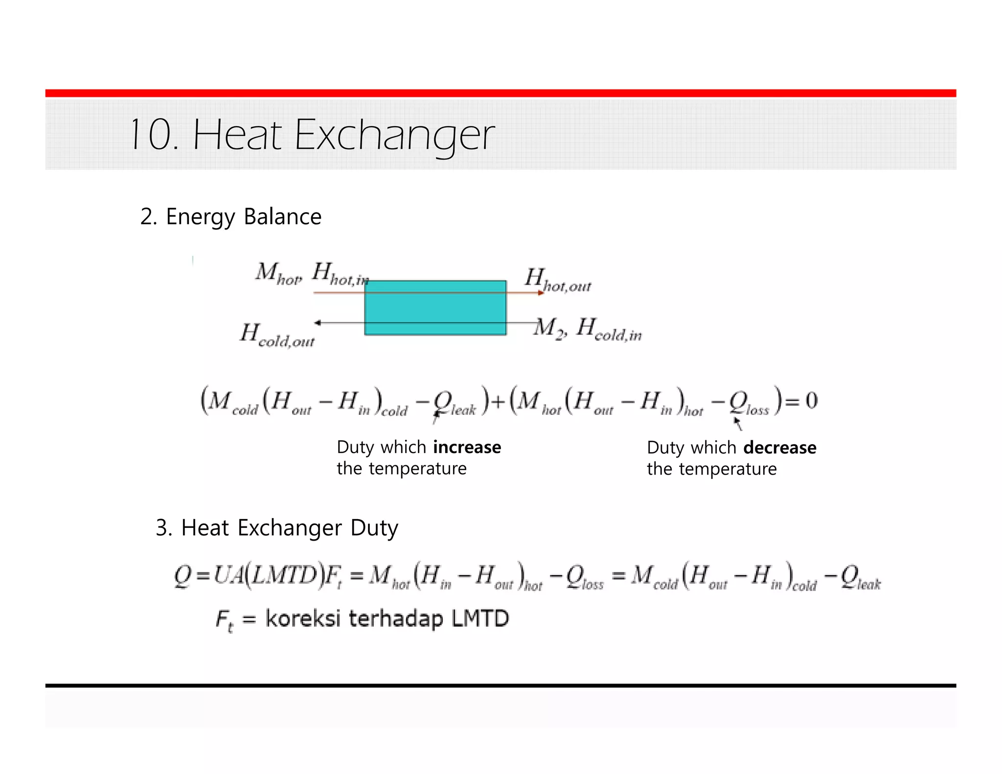
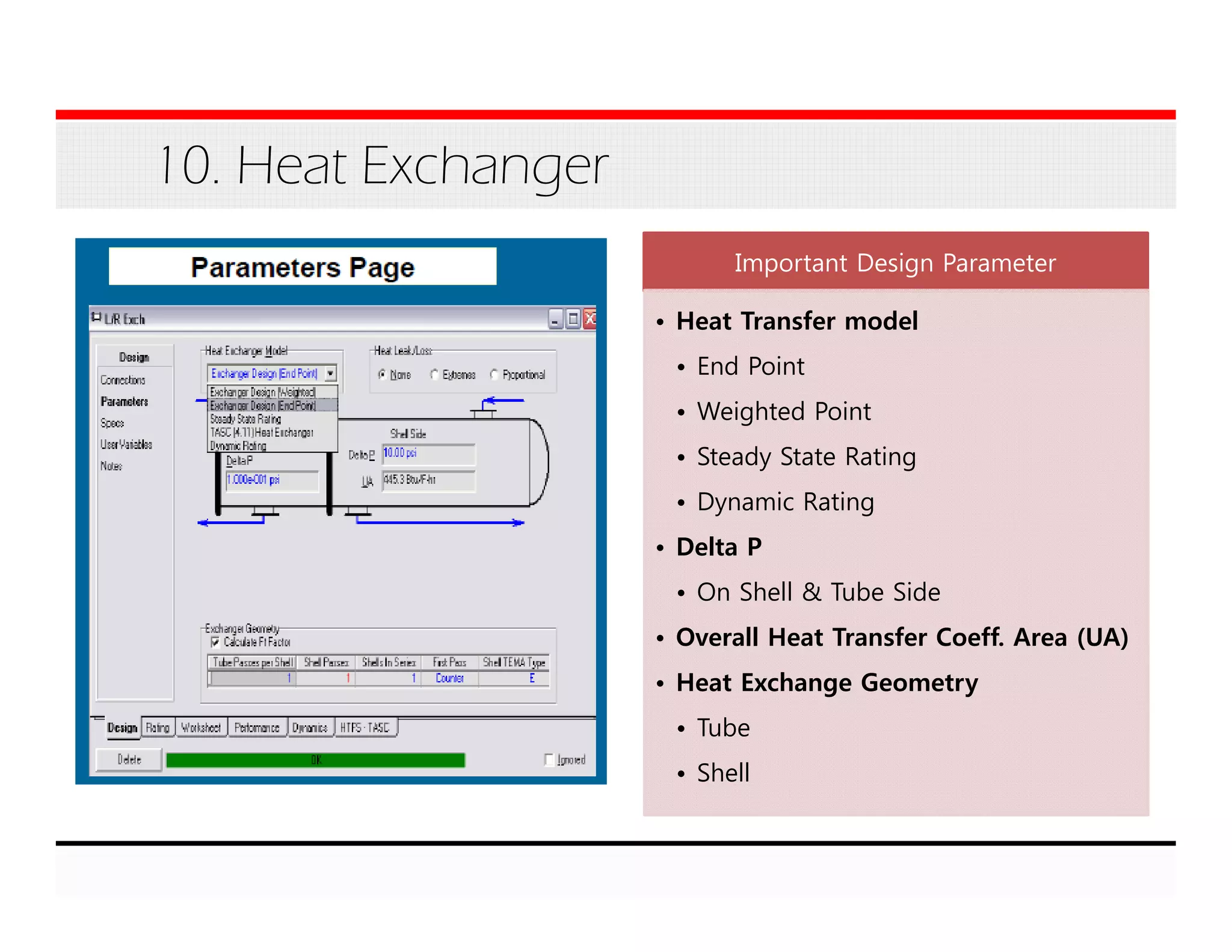
Basic Equation:
[Mcold x ΔHcold – Qleak]- (Mhot x ΔHhot – Qloss]
= Balance Error = 0 (Typically)
Heat Exchanger has two sided:
- Hot Side
- Cold Side](https://image.slidesharecdn.com/module3-basicequipment-150227020102-conversion-gate02/75/Module-3-Basic-Equipment-33-2048.jpg)

The document is a training module on basic equipment used in Aspen HYSYS, covering units such as mixers, pumps, compressors, and reactors, along with their functions, design parameters, and objectives. It includes detailed descriptions of unit operations like separation, heat exchangers, and distillation processes, providing essential calculations and methodologies for chemical process simulation. Additionally, various reactor types and their applications in chemical reactions are discussed with practical examples and exercises.


