Pengantar DPHE.pptxIntroduction of Heat Exchanger Design 2nd week
1.
INSTITUT TEKNOLOGI KALIMANTAN
CHE M IC A L E N GI NE E R I NG
I N S T I T U T T E K N O L O G I K A L I M A N TA N
c h e. itk. ac .id
HEAT EXCHANGER
Heat Exchanger
Design
R i z k a L e s t a r i , S .T. , M . E n g
2.
INSTITUT TEKNOLOGI KALIMANTAN
CHE M IC A L E N GI NE E R I NG
I N S T I T U T T E K N O L O G I K A L I M A N TA N
c h e. itk. ac .id
Course Design:
Couse learning
outcome
Able to
analyze
heat
exchanger
design
(C4)
Able to
describe heat
exchanger
operation unit
and their
classification
in industry. Able to describe
the principle of
DPHE and STHE
and their
specification
calculation.
Able to describe
the principle of
condenser and
their specification
calculation.
Able to
describe the
principle of
vaporizer and
their
specification
calculation.
Able to describe
the principle of
reboiler and
their
specification
calculation.
Able to describe
the principle of
thermosyphon
and their
specification
calculation.
3.
INSTITUT TEKNOLOGI KALIMANTAN
CHE M IC A L E N GI NE E R I NG
I N S T I T U T T E K N O L O G I K A L I M A N TA N
c h e. itk. ac .id
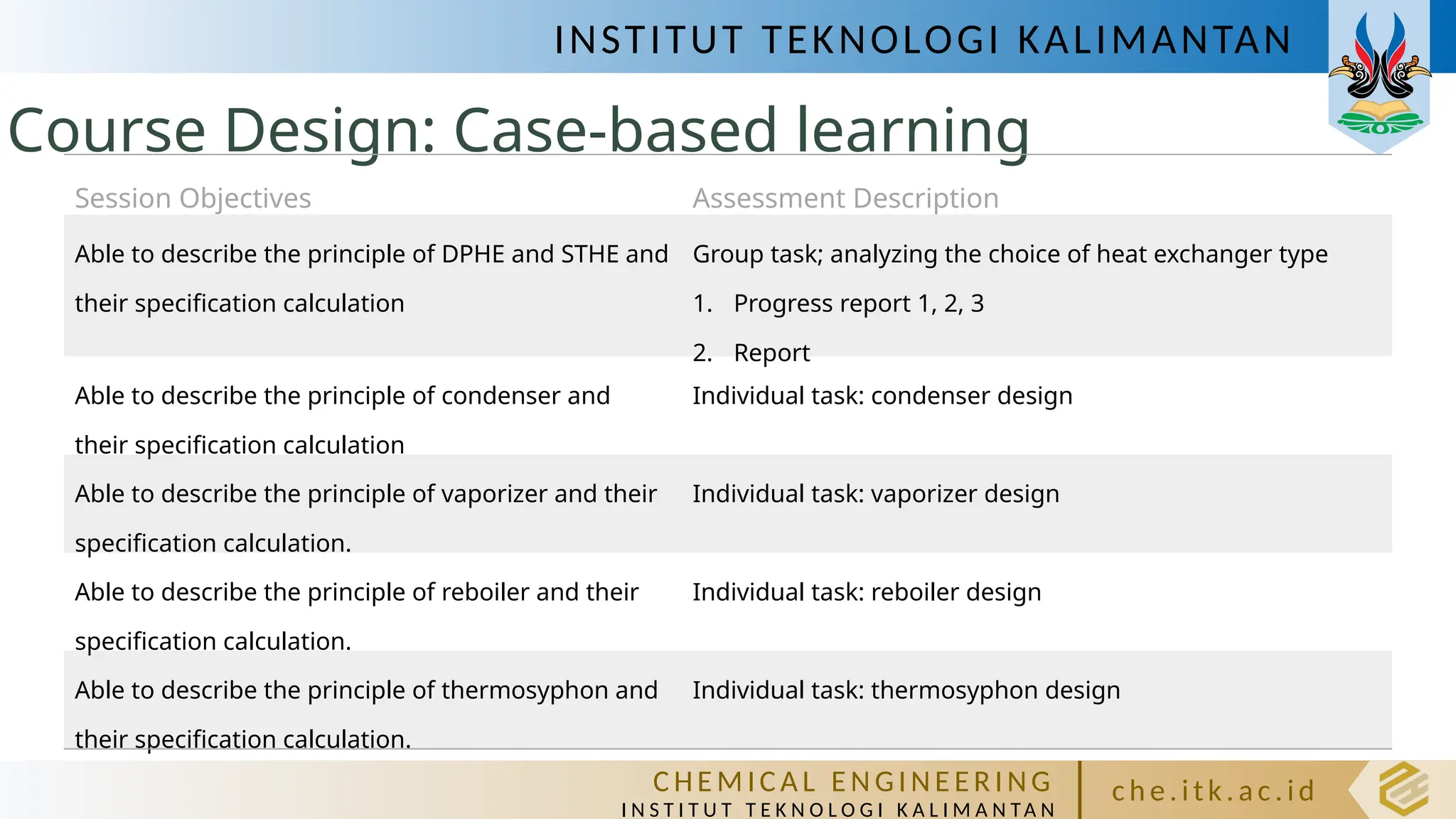
Course Design: Case-based learning
Session Objectives Assessment Description
Able to describe the principle of DPHE and STHE and
their specification calculation
Group task; analyzing the choice of heat exchanger type
1. Progress report 1, 2, 3
2. Report
Able to describe the principle of condenser and
their specification calculation
Individual task: condenser design
Able to describe the principle of vaporizer and their
specification calculation.
Individual task: vaporizer design
Able to describe the principle of reboiler and their
specification calculation.
Individual task: reboiler design
Able to describe the principle of thermosyphon and
their specification calculation.
Individual task: thermosyphon design
4.
INSTITUT TEKNOLOGI KALIMANTAN
CHE M IC A L E N GI NE E R I NG
I N S T I T U T T E K N O L O G I K A L I M A N TA N
c h e. itk. ac .id
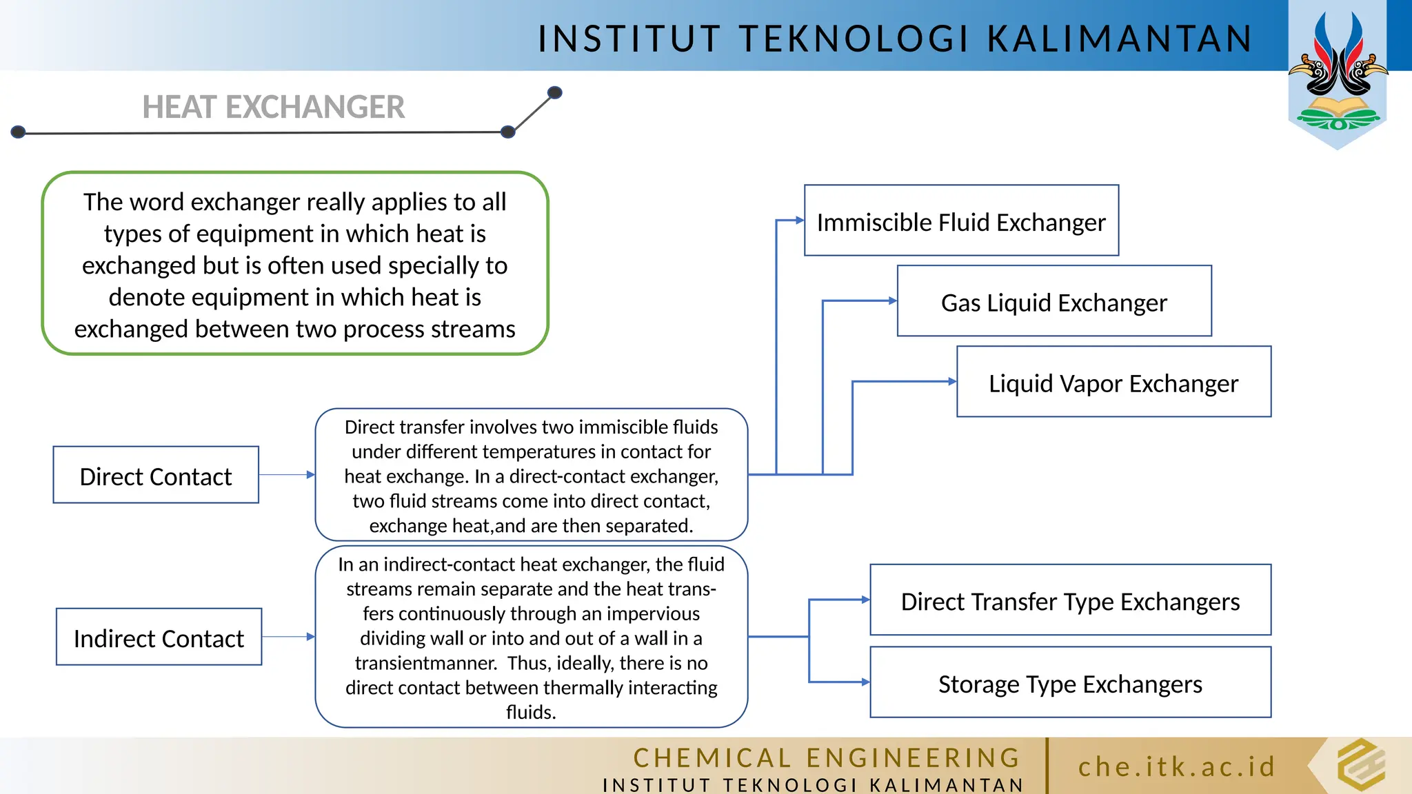
HEAT EXCHANGER
The word exchanger really applies to all
types of equipment in which heat is
exchanged but is often used specially to
denote equipment in which heat is
exchanged between two process streams
Direct Contact
Indirect Contact
Direct transfer involves two immiscible fluids
under different temperatures in contact for
heat exchange. In a direct-contact exchanger,
two fluid streams come into direct contact,
exchange heat,and are then separated.
In an indirect-contact heat exchanger, the fluid
streams remain separate and the heat trans-
fers continuously through an impervious
dividing wall or into and out of a wall in a
transientmanner. Thus, ideally, there is no
direct contact between thermally interacting
fluids.
Immiscible Fluid Exchanger
Gas Liquid Exchanger
Liquid Vapor Exchanger
Direct Transfer Type Exchangers
Storage Type Exchangers
5.
INSTITUT TEKNOLOGI KALIMANTAN
CHE M IC A L E N GI NE E R I NG
I N S T I T U T T E K N O L O G I K A L I M A N TA N
c h e. itk. ac .id
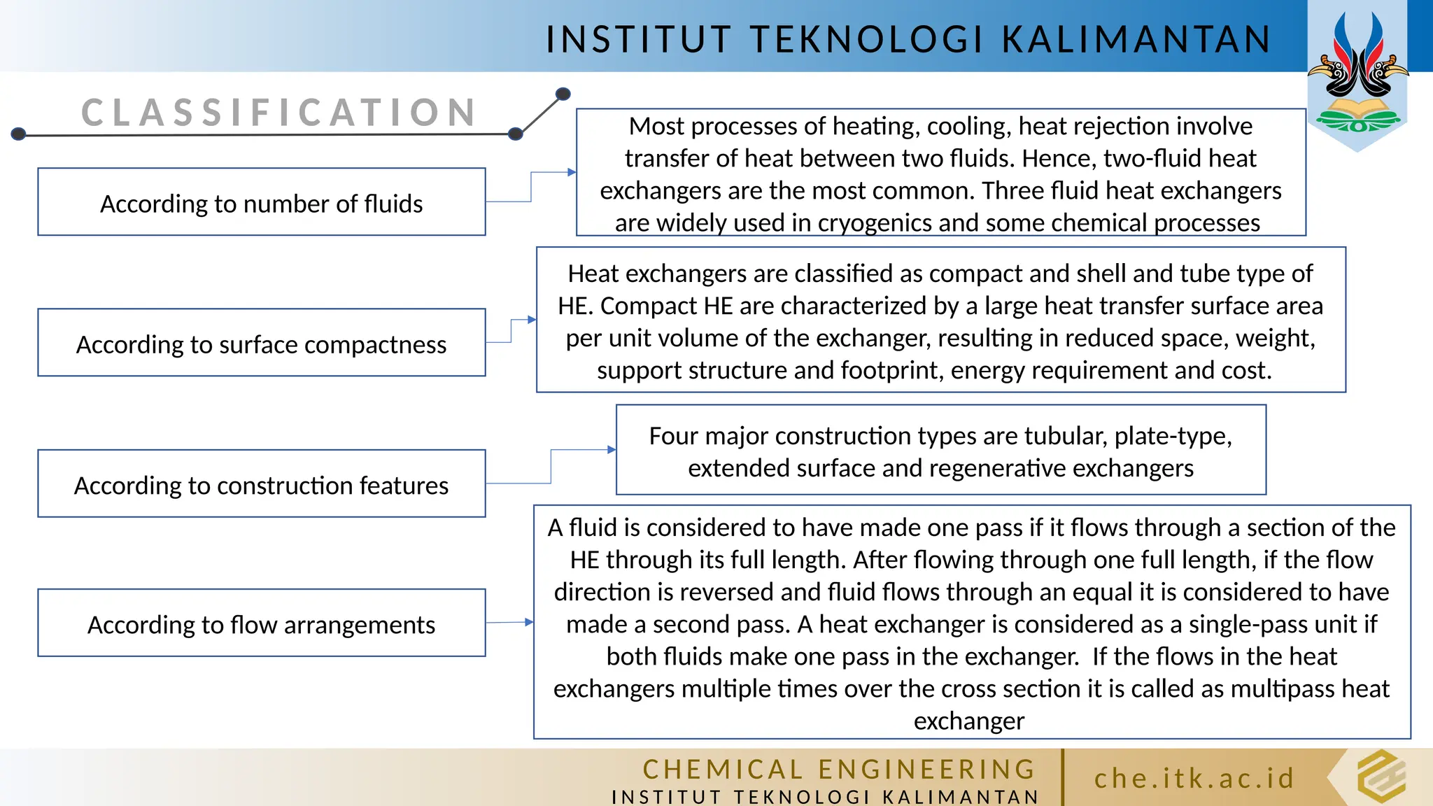
C L A S S I F I C AT I O N
According to number of fluids
According to surface compactness
According to construction features
According to flow arrangements
Most processes of heating, cooling, heat rejection involve
transfer of heat between two fluids. Hence, two-fluid heat
exchangers are the most common. Three fluid heat exchangers
are widely used in cryogenics and some chemical processes
Heat exchangers are classified as compact and shell and tube type of
HE. Compact HE are characterized by a large heat transfer surface area
per unit volume of the exchanger, resulting in reduced space, weight,
support structure and footprint, energy requirement and cost.
Four major construction types are tubular, plate-type,
extended surface and regenerative exchangers
A fluid is considered to have made one pass if it flows through a section of the
HE through its full length. After flowing through one full length, if the flow
direction is reversed and fluid flows through an equal it is considered to have
made a second pass. A heat exchanger is considered as a single-pass unit if
both fluids make one pass in the exchanger. If the flows in the heat
exchangers multiple times over the cross section it is called as multipass heat
exchanger
6.
INSTITUT TEKNOLOGI KALIMANTAN
CHE M IC A L E N GI NE E R I NG
I N S T I T U T T E K N O L O G I K A L I M A N TA N
c h e. itk. ac .id
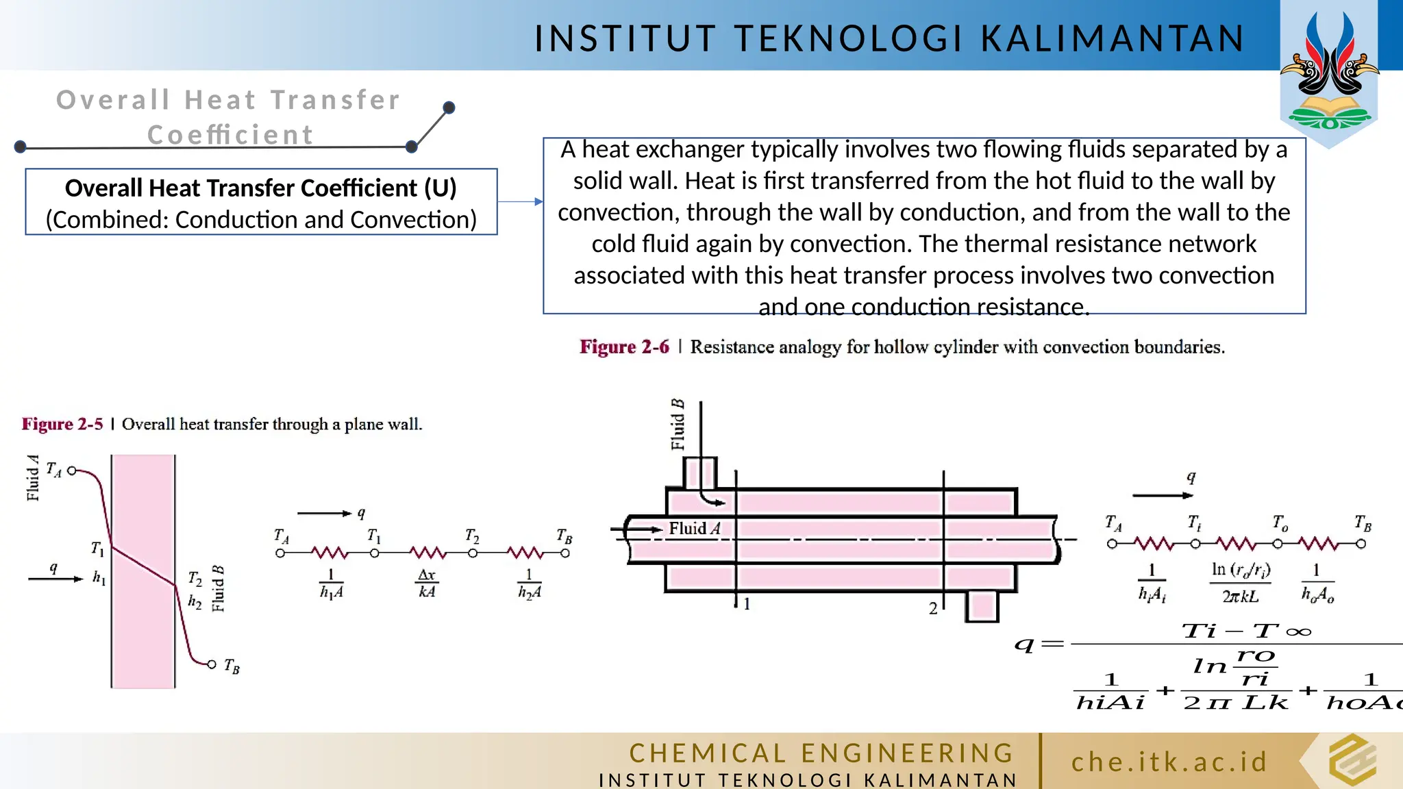
Ove ral l Heat Tra n sfer
Co effi c ie nt
Overall Heat Transfer Coefficient (U)
(Combined: Conduction and Convection)
A heat exchanger typically involves two flowing fluids separated by a
solid wall. Heat is first transferred from the hot fluid to the wall by
convection, through the wall by conduction, and from the wall to the
cold fluid again by convection. The thermal resistance network
associated with this heat transfer process involves two convection
and one conduction resistance.
𝑞=
𝑇𝑖 − 𝑇 ∞
1
h𝑖𝐴𝑖
+
𝑙𝑛
𝑟𝑜
𝑟𝑖
2 𝜋 𝐿𝑘
+
1
h𝑜𝐴𝑜
7.
INSTITUT TEKNOLOGI KALIMANTAN
CHE M IC A L E N GI NE E R I NG
I N S T I T U T T E K N O L O G I K A L I M A N TA N
c h e. itk. ac .id
Ove ral l Heat Tra n sfer
Co effi c ie nt
With assumption:
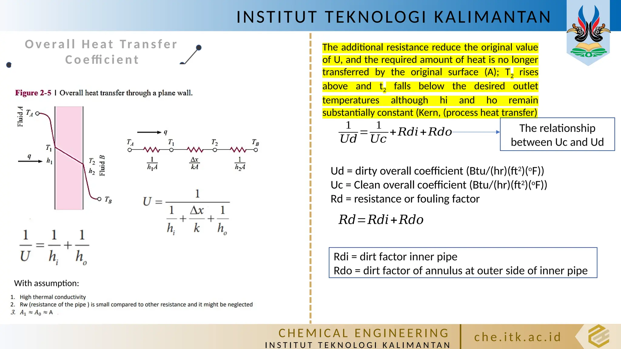
The additional resistance reduce the original value
of U, and the required amount of heat is no longer
transferred by the original surface (A); T2 rises
above and t2 falls below the desired outlet
temperatures although hi and ho remain
substantially constant (Kern, (process heat transfer)
1
𝑈𝑑
=
1
𝑈𝑐
+𝑅𝑑𝑖+𝑅𝑑𝑜
Ud = dirty overall coefficient (Btu/(hr)(ft2
)(o
F))
Uc = Clean overall coefficient (Btu/(hr)(ft2
)(o
F))
Rd = resistance or fouling factor
The relationship
between Uc and Ud
𝑅𝑑=𝑅𝑑𝑖+𝑅𝑑𝑜
Rdi = dirt factor inner pipe
Rdo = dirt factor of annulus at outer side of inner pipe
8.
INSTITUT TEKNOLOGI KALIMANTAN
CHE M IC A L E N GI NE E R I NG
I N S T I T U T T E K N O L O G I K A L I M A N TA N
c h e. itk. ac .id
Fouling Factors
Fouling Factors
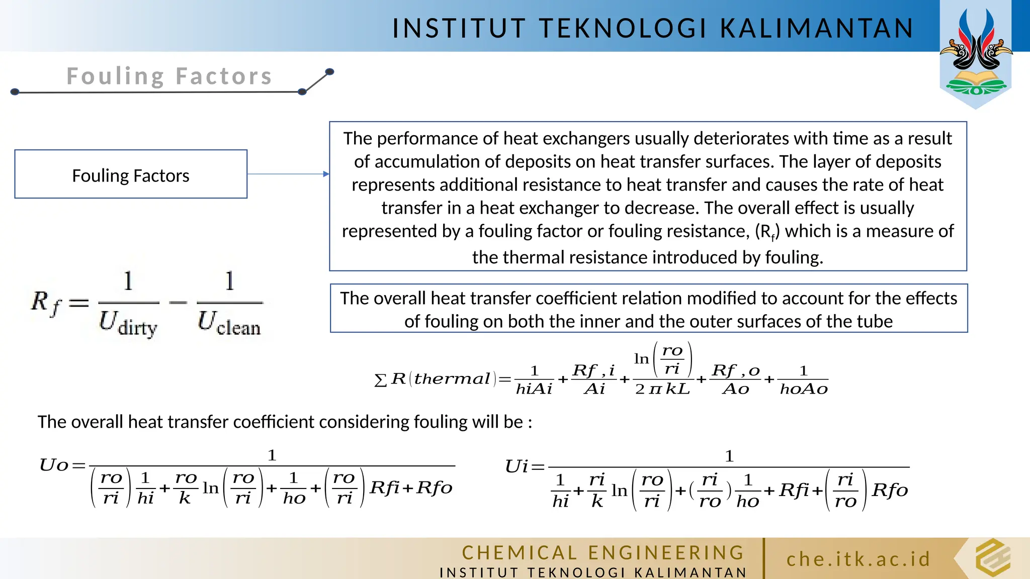
The performance of heat exchangers usually deteriorates with time as a result
of accumulation of deposits on heat transfer surfaces. The layer of deposits
represents additional resistance to heat transfer and causes the rate of heat
transfer in a heat exchanger to decrease. The overall effect is usually
represented by a fouling factor or fouling resistance, (Rf) which is a measure of
the thermal resistance introduced by fouling.
∑ 𝑅 ( h
𝑡 𝑒𝑟𝑚𝑎𝑙 )=
1
h𝑖𝐴𝑖
+
𝑅𝑓 , 𝑖
𝐴𝑖
+
ln(𝑟𝑜
𝑟𝑖 )
2 𝜋 𝑘𝐿
+
𝑅𝑓 , 𝑜
𝐴𝑜
+
1
h𝑜𝐴𝑜
The overall heat transfer coefficient relation modified to account for the effects
of fouling on both the inner and the outer surfaces of the tube
𝑈𝑜=
1
(𝑟𝑜
𝑟𝑖 ) 1
h𝑖
+
𝑟𝑜
𝑘
ln(𝑟𝑜
𝑟𝑖 )+
1
h𝑜
+(𝑟𝑜
𝑟𝑖 )𝑅𝑓𝑖+𝑅𝑓𝑜
𝑈𝑖=
1
1
h𝑖
+
𝑟𝑖
𝑘
ln(𝑟𝑜
𝑟𝑖 )+(
𝑟𝑖
𝑟𝑜
)
1
h𝑜
+ 𝑅𝑓𝑖+( 𝑟𝑖
𝑟𝑜 )𝑅𝑓𝑜
The overall heat transfer coefficient considering fouling will be :
9.
INSTITUT TEKNOLOGI KALIMANTAN
CHE M IC A L E N GI NE E R I NG
I N S T I T U T T E K N O L O G I K A L I M A N TA N
c h e. itk. ac .id
HEAT EXCHANGER
D e s a i n A l a t
Pe n u k a r Pa n a s
H e a t E xc h a n g e r
C o u n t e r fl o w :
D o u b l e p i p e E xc h a n g e r
10.
INSTITUT TEKNOLOGI KALIMANTAN
CHE M IC A L E N GI NE E R I NG
I N S T I T U T T E K N O L O G I K A L I M A N TA N
c h e. itk. ac .id
Double Pipe Heat-Exchanger (DPHE)
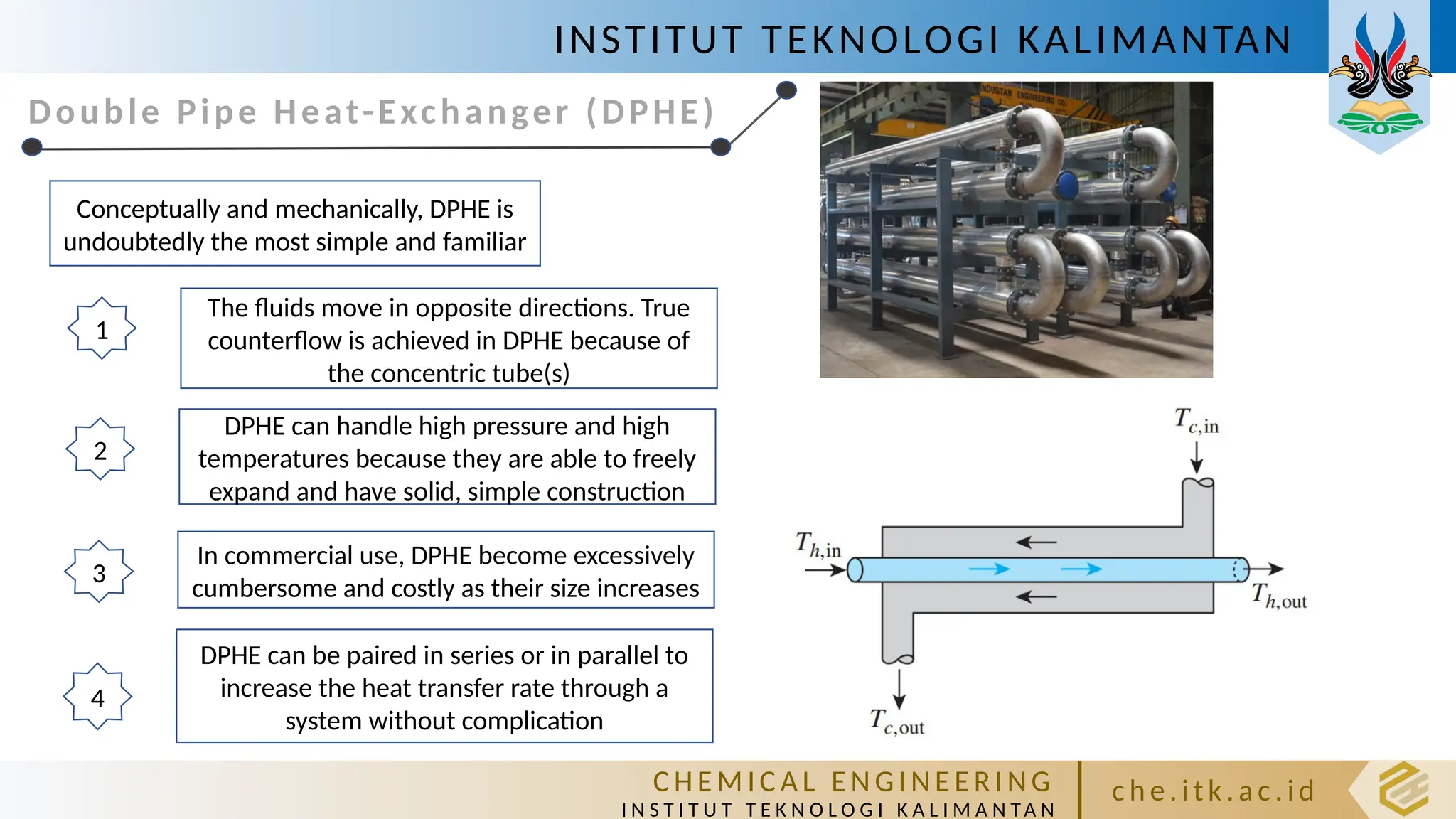
Conceptually and mechanically, DPHE is
undoubtedly the most simple and familiar
The fluids move in opposite directions. True
counterflow is achieved in DPHE because of
the concentric tube(s)
1
In commercial use, DPHE become excessively
cumbersome and costly as their size increases
3
DPHE can handle high pressure and high
temperatures because they are able to freely
expand and have solid, simple construction
2
DPHE can be paired in series or in parallel to
increase the heat transfer rate through a
system without complication
4
11.
INSTITUT TEKNOLOGI KALIMANTAN
CHE M IC A L E N GI NE E R I NG
I N S T I T U T T E K N O L O G I K A L I M A N TA N
c h e. itk. ac .id
12.
INSTITUT TEKNOLOGI KALIMANTAN
CHE M IC A L E N GI NE E R I NG
I N S T I T U T T E K N O L O G I K A L I M A N TA N
c h e. itk. ac .id
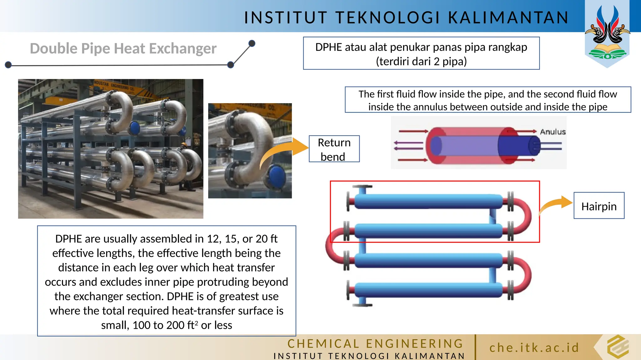
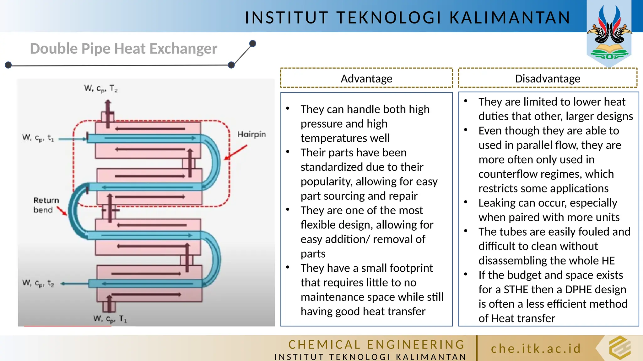
Double Pipe Heat Exchanger DPHE atau alat penukar panas pipa rangkap
(terdiri dari 2 pipa)
Return
bend
The first fluid flow inside the pipe, and the second fluid flow
inside the annulus between outside and inside the pipe
Hairpin
DPHE are usually assembled in 12, 15, or 20 ft
effective lengths, the effective length being the
distance in each leg over which heat transfer
occurs and excludes inner pipe protruding beyond
the exchanger section. DPHE is of greatest use
where the total required heat-transfer surface is
small, 100 to 200 ft2
or less
13.
INSTITUT TEKNOLOGI KALIMANTAN
CHE M IC A L E N GI NE E R I NG
I N S T I T U T T E K N O L O G I K A L I M A N TA N
c h e. itk. ac .id
Double Pipe Heat Exchanger
Advantage Disadvantage
• They can handle both high
pressure and high
temperatures well
• Their parts have been
standardized due to their
popularity, allowing for easy
part sourcing and repair
• They are one of the most
flexible design, allowing for
easy addition/ removal of
parts
• They have a small footprint
that requires little to no
maintenance space while still
having good heat transfer
• They are limited to lower heat
duties that other, larger designs
• Even though they are able to
used in parallel flow, they are
more often only used in
counterflow regimes, which
restricts some applications
• Leaking can occur, especially
when paired with more units
• The tubes are easily fouled and
difficult to clean without
disassembling the whole HE
• If the budget and space exists
for a STHE then a DPHE design
is often a less efficient method
of Heat transfer
14.
INSTITUT TEKNOLOGI KALIMANTAN
CHE M IC A L E N GI NE E R I NG
I N S T I T U T T E K N O L O G I K A L I M A N TA N
c h e. itk. ac .id
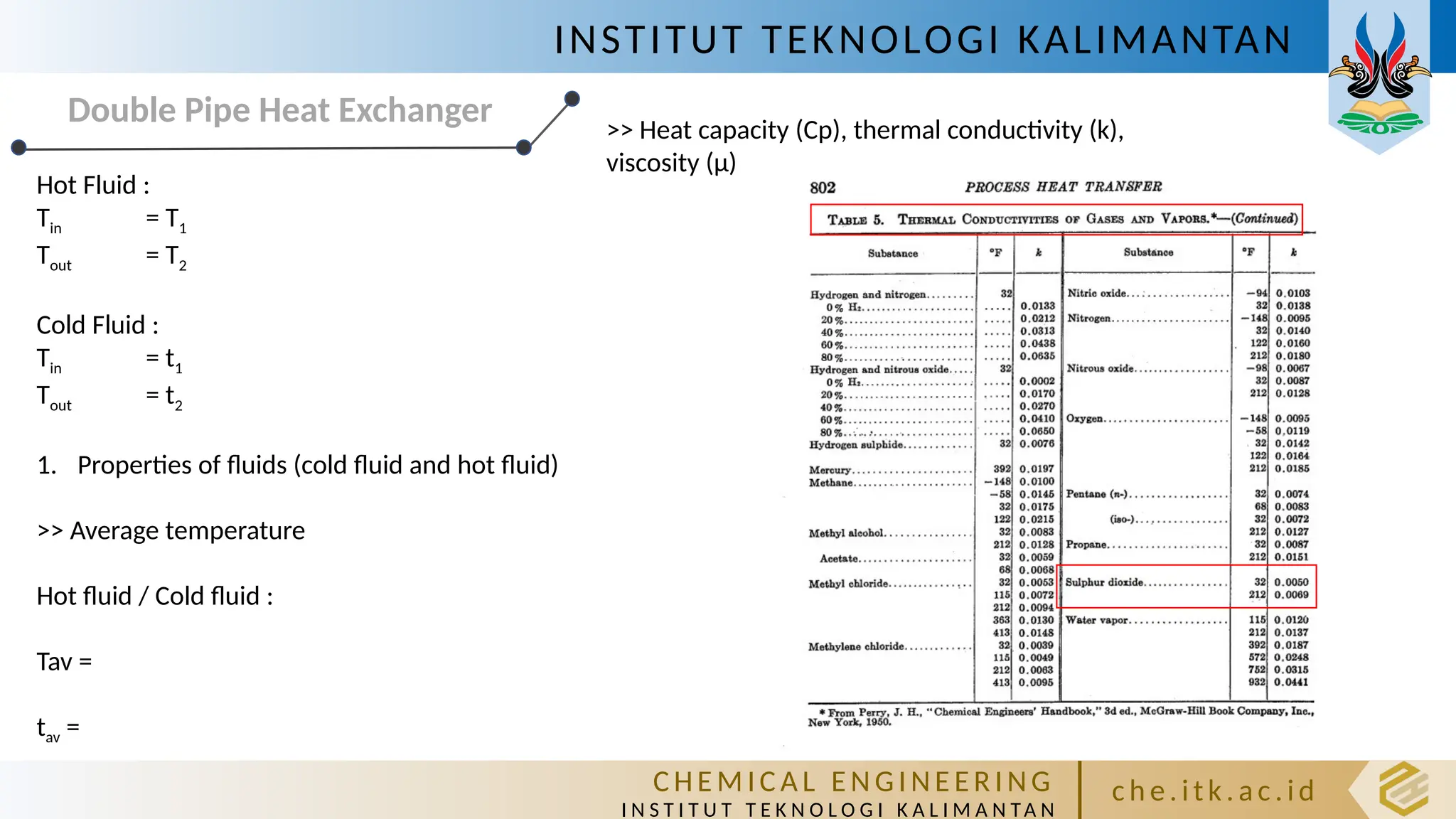
Double Pipe Heat Exchanger
Hot Fluid :
Tin = T1
Tout = T2
Cold Fluid :
Tin = t1
Tout = t2
1. Properties of fluids (cold fluid and hot fluid)
>> Average temperature
Hot fluid / Cold fluid :
Tav =
tav =
>> Heat capacity (Cp), thermal conductivity (k),
viscosity (µ)
15.
INSTITUT TEKNOLOGI KALIMANTAN
CHE M IC A L E N GI NE E R I NG
I N S T I T U T T E K N O L O G I K A L I M A N TA N
c h e. itk. ac .id
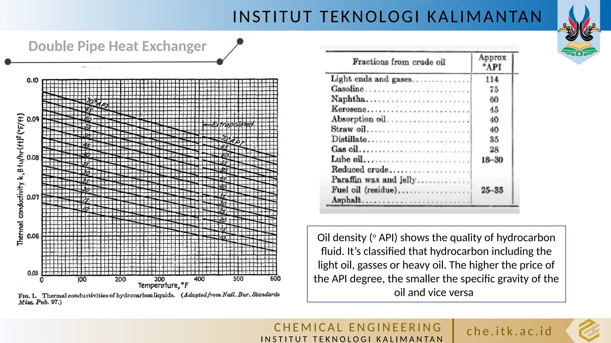
Double Pipe Heat Exchanger
Oil density (o
API) shows the quality of hydrocarbon
fluid. It’s classified that hydrocarbon including the
light oil, gasses or heavy oil. The higher the price of
the API degree, the smaller the specific gravity of the
oil and vice versa


![Heat_exchanger_1[7537].pptx](https://cdn.slidesharecdn.com/ss_thumbnails/heatexchanger17537-230514132732-295f8f89-thumbnail.jpg?width=640&height=640&fit=bounds)


![[BROCHURE] Italy Tour Project | @SlideON](https://cdn.slidesharecdn.com/ss_thumbnails/brochure8-251215152319-2805af68-thumbnail.jpg?width=640&height=640&fit=bounds)

![Chapter4_Initiation_of_Sediment_Motion_v2[1].pptx](https://cdn.slidesharecdn.com/ss_thumbnails/chapter4initiationofsedimentmotionv21-251208223747-f94ef163-thumbnail.jpg?width=640&height=640&fit=bounds)


![Chapt_4[1].ppt very interseting and important](https://cdn.slidesharecdn.com/ss_thumbnails/chapt41-251208222956-7cf5e0fa-thumbnail.jpg?width=640&height=640&fit=bounds)


