Download as PDF, PPTX

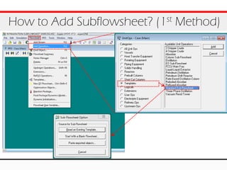
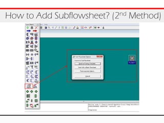

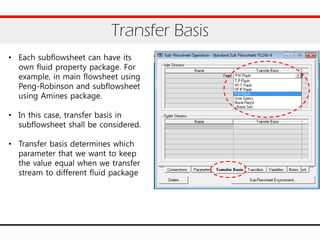
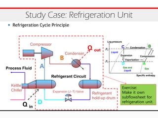
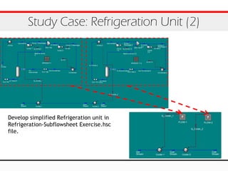


The document outlines the use of subflowsheets in Aspen HYSYS for simulating complex processing facilities through a multi-level flowsheet architecture. It details methods for adding subflowsheets, such as using existing templates or creating blank flowsheets, and emphasizes the significance of transfer basis in defining parameters for fluid packages. Additionally, it includes exercises related to developing a simplified refrigeration unit within a subflowsheet.


![Kbr[1] report](https://cdn.slidesharecdn.com/ss_thumbnails/kbr1-160104072613-thumbnail.jpg?width=640&height=640&fit=bounds)


