Downloaded 118 times


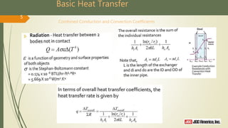
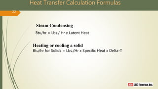
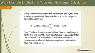
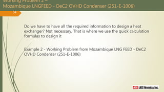
![“Quick” Heat Transfer Calculation Formulas – for Estimation
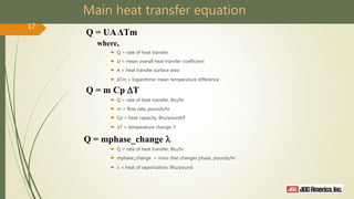
General
Liquid:
20
–
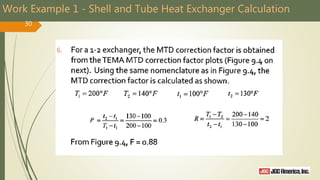
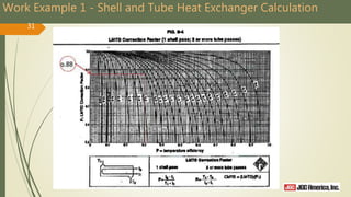
Btu
hr
= kW × 3412 = HP × 2544
–
Lbs
hr
= GPM x Density 8.022 = GPM × 501.375 × Specific Gravity
Specific Gravity = Density/62.4 Psia = Psig+14.7
–
Btu
hr
= Tons of Refrigeration × 12000
–
Btu
hr
= Evaporative Cooling Tower Tons x 15000
– SCFM of air = [ACFM x (psig + 14.7) x 528] / [(Temp + 460) x 14.7]
– SCFM of air = Lbs/ Hr of air / 4.5 (at atmospheric temperature and pressure)](https://image.slidesharecdn.com/heatexchangertraining02-161205230322/85/Heat-exchanger-training-02-25-15-20-320.jpg)
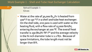
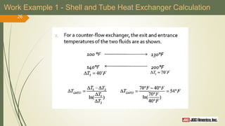
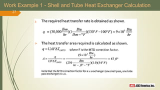
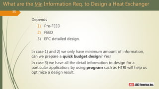
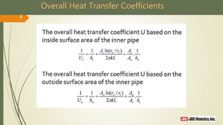
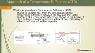
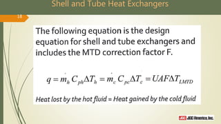
![Approach of a Temperature Difference (ATD)
Condensate Supply Temp. (°C) = achieve T (-16) – rise T (-3) – ATD (-3) = -22.3 (°C)
38
Streams
Hot Side Cold Side
112 113 374 375
Temperature [C] -0.14 -16.3 -22.3 -19.3
Pressure [bara] 26.7 26.7 2.5 2.5
Mass Flow [kg/h] 3980 3980 4500 4500](https://image.slidesharecdn.com/heatexchangertraining02-161205230322/85/Heat-exchanger-training-02-25-15-38-320.jpg)
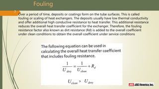
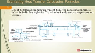
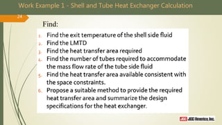
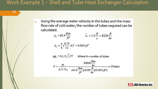
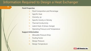
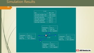
![Calculate Heat Exchanger Duty Required
39
Streams 1 2 3 4
Temperature [C] tc1
tc2
Th1
Th2
-0.14 -16.3 -22.3 -19.3
Pressure [bara] 26.7 26.7 2.5 2.5
Mass Flow [kg/h] 3980 3980 4500 4500
ΔTLM
(°C) 11.35
UA (Kw/°C) 33 - 40 From Go-By
For UA = 33 Q (Kw) = 375
For UA = 40 Q (Kw) = 454
Result UniSim Results
Q = UA ΔTLM](https://image.slidesharecdn.com/heatexchangertraining02-161205230322/85/Heat-exchanger-training-02-25-15-39-320.jpg)
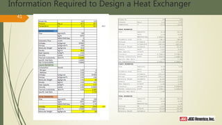


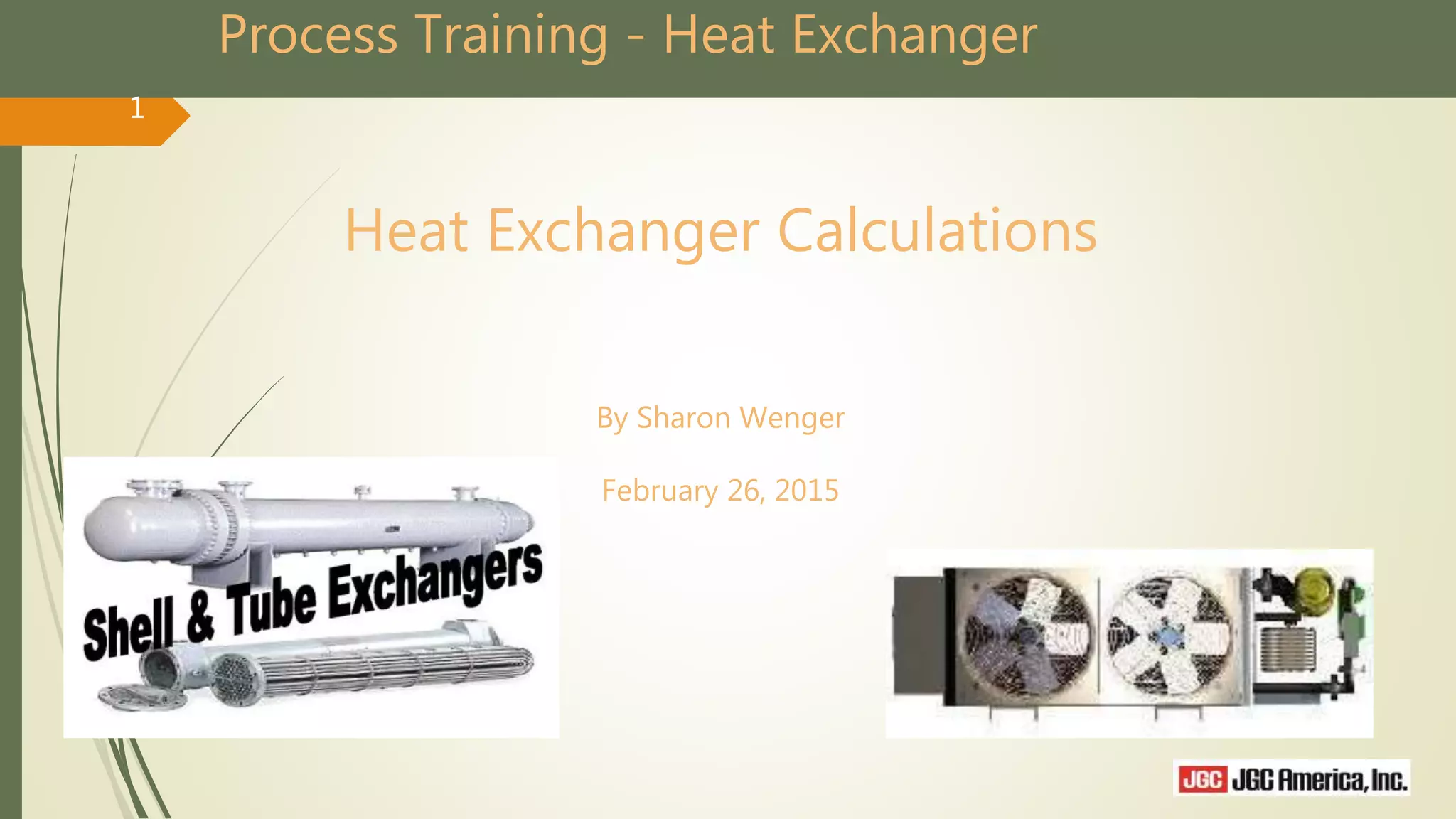
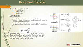
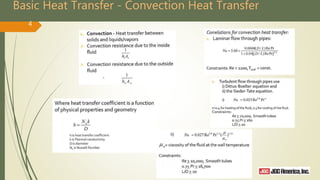
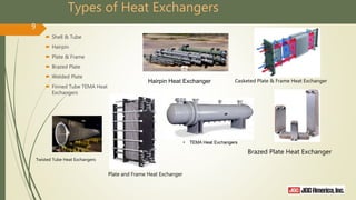
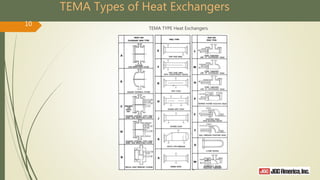
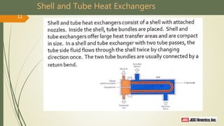
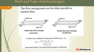
The document provides an overview of heat exchanger calculations and heat transfer principles, including conduction, convection, and radiation. It details various types of heat exchangers and their operational principles, including shell and tube, plate and frame, and others, along with heat transfer calculation formulas and worked examples. Additionally, it discusses essential factors for designing heat exchangers, such as fluid properties and operational parameters.