
Download as PDF, PPTX

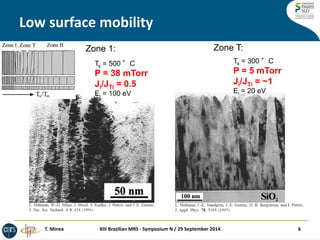
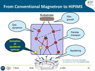
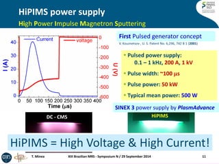
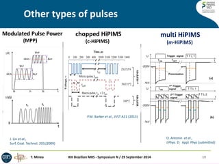
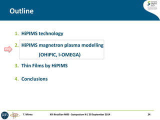
![Pulse time [μs]
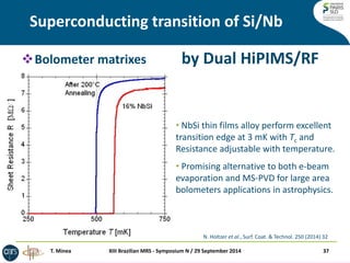
Ganciu et al, US Patent No. 7, 927, 466 B2 (19 April 2011)
Fast HiPIMS with pre-ionization
Average Power 80 W
Pulse width ~10 μs
Frequency < 1kHz
Umax ~ 1kV
Imax ~ 100 A
16
SHORT & FAST Pulsed generator concept [2]; developed 2004
XIII Brazilian MRS - Symposium N / 29 September 2014
T. Minea](https://image.slidesharecdn.com/mineasbpmat29sept2014print-141016090509-conversion-gate02/85/HiPIMS-technology-physics-and-thin-film-applications-16-320.jpg)

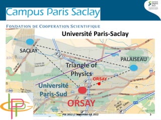
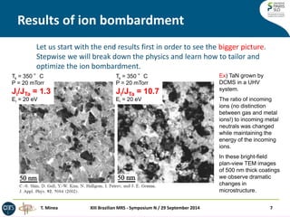
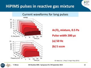
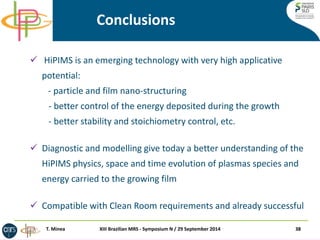
![HiPIMS current
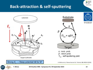
XIII Brazilian MRS - Symposium N / 29 September 2014
26
0 2 4 6 8 10
Pulse time [μs]
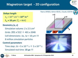
OHIPIC: Orsay HIgh density plasma Particle-In-Cell model
Experiment using fast pre-ionization HiPIMS
OHIPIC model simulated discharge current
0 1 2 3 4 5 6
Pulse time [μs]
0
-300
- 600
Voltage (V)
Current
T. Minea et al, Surf. Coat. Tech. 255, (2014) 52
T. Minea](https://image.slidesharecdn.com/mineasbpmat29sept2014print-141016090509-conversion-gate02/85/HiPIMS-technology-physics-and-thin-film-applications-26-320.jpg)
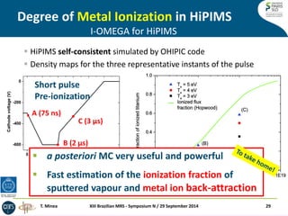
The document discusses high power impulse magnetron sputtering (HIPIMS) technology and its applications in thin film deposition. It outlines the advantages and challenges of HIPIMS, including the importance of precursor ionization, microstructure, and control of deposition parameters. Additionally, it covers recent advances in modeling and experimentation related to HIPIMS processes and the impact of different parameters on film quality.


![Thin_Film_Technology_introduction[1]](https://cdn.slidesharecdn.com/ss_thumbnails/1b4496c8-2102-411b-8465-a3dd3f398327-150205034538-conversion-gate02-thumbnail.jpg?width=640&height=640&fit=bounds)


![Ashish ranjan( chemistry project[ acid rain] )](https://cdn.slidesharecdn.com/ss_thumbnails/ashishranjanchemistryprojectacidrain-140222051907-phpapp02-thumbnail.jpg?width=640&height=640&fit=bounds)


