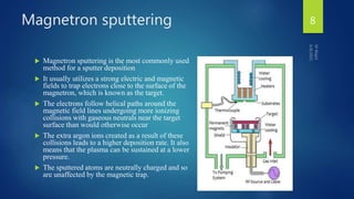
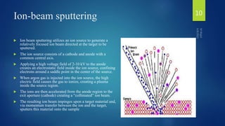
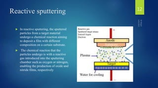
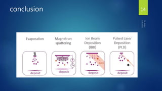
Muhammad Wajid
Reg# CIIT/FA20-PPH-003/ISB
Muhammad Talha
Reg# CIIT/FA20-PPH-001/ISB
Department of Physics
COMSATS University Islamabad
Presented to
Dr. Shumaila Karmat
Assistant Professor
Department of Physics
COMSATS University Islamabad
Sputtering Process and its Types
6/8/2021
M Wajid
1
Thin films
 Thin films are thin material layer
ranging from fractions of a nanometer
(monolayer)To several micrometers in thickness
2
Synthesis of thin film 3
Sputtering process
 Sputtering is a term used to describe the mechanism in which atom
are ejected from the surface of the material when that surface is
stuck by sufficient energetic particles
 First discovered in 1852, and developed as thin film deposition
technique by Langmuir in 1920.
 Metallic film: Al-alloys, Ti, Tantalum, Nickel ,Cobalt ,Gold etc.
4
Basic model 5
Sputtering process 6
Types of sputtering deposition
 Magnetron sputtering
 Ion-beam sputtering
 Reactive sputtering
 Ion-assisted deposition
 High target utilization sputtering (HiTUS)
 High- power impulse magnetron sputtering (HiPlMS)
 Gas flow sputtering
7
Magnetron sputtering
 Magnetron sputtering is the most commonly used
method for a sputter deposition
 It usually utilizes a strong electric and magnetic
fields to trap electrons close to the surface of the
magnetron, which is known as the target.
 The electrons follow helical paths around the
magnetic field lines undergoing more ionizing
collisions with gaseous neutrals near the target
surface than would otherwise occur
 The extra argon ions created as a result of these
collisions leads to a higher deposition rate. It also
means that the plasma can be sustained at a lower
pressure.
 The sputtered atoms are neutrally charged and so
are unaffected by the magnetic trap.
8
Magnetron sputtering 9
Ion-beam sputtering
 Ion beam sputtering utilizes an ion source to generate a
relatively focused ion beam directed at the target to be
sputtered.
 The ion source consists of a cathode and anode with a
common central axis.
 Applying a high voltage field of 2-10 kV to the anode
creates an electrostatic field inside the ion source, confining
electrons around a saddle point in the center of the source.
 When argon gas is injected into the ion source, the high
electric field causes the gas to ionize, creating a plasma
inside the source region.
 The ions are then accelerated from the anode region to the
exit aperture (cathode) creating a “collimated” ion beam.
 The resulting ion beam impinges upon a target material and,
via momentum transfer between the ion and the target,
sputters this material onto the sample
10
Ion-beam sputtering 11
Reactive sputtering
 In reactive sputtering, the sputtered
particles from a target material
undergo a chemical reaction aiming
to deposit a film with different
composition on a certain substrate.
 The chemical reaction that the
particles undergo is with a reactive
gas introduced into the sputtering
chamber such as oxygen or nitrogen,
enabling the production of oxide and
nitride films, respectively
12
Application of sputtering
 Heads-up cockpit displays
 Jet turbine engines
 Mirrors for optical and x-ray telescopes
 Night vision equipment.
 Anti-corrosion coatings
 Anti-seize coatings
 Dies and molds
 Sewing needles
 Tool and drill bit hardening.
13
conclusion 14
15

Sputtering process and its types

  • 1.
    Muhammad Wajid Reg# CIIT/FA20-PPH-003/ISB MuhammadTalha Reg# CIIT/FA20-PPH-001/ISB Department of Physics COMSATS University Islamabad Presented to Dr. Shumaila Karmat Assistant Professor Department of Physics COMSATS University Islamabad Sputtering Process and its Types 6/8/2021 M Wajid 1
  • 2.
    Thin films  Thinfilms are thin material layer ranging from fractions of a nanometer (monolayer)To several micrometers in thickness 2
  • 3.
  • 4.
    Sputtering process  Sputteringis a term used to describe the mechanism in which atom are ejected from the surface of the material when that surface is stuck by sufficient energetic particles  First discovered in 1852, and developed as thin film deposition technique by Langmuir in 1920.  Metallic film: Al-alloys, Ti, Tantalum, Nickel ,Cobalt ,Gold etc. 4
  • 5.
  • 6.
  • 7.
    Types of sputteringdeposition  Magnetron sputtering  Ion-beam sputtering  Reactive sputtering  Ion-assisted deposition  High target utilization sputtering (HiTUS)  High- power impulse magnetron sputtering (HiPlMS)  Gas flow sputtering 7
  • 8.
    Magnetron sputtering  Magnetronsputtering is the most commonly used method for a sputter deposition  It usually utilizes a strong electric and magnetic fields to trap electrons close to the surface of the magnetron, which is known as the target.  The electrons follow helical paths around the magnetic field lines undergoing more ionizing collisions with gaseous neutrals near the target surface than would otherwise occur  The extra argon ions created as a result of these collisions leads to a higher deposition rate. It also means that the plasma can be sustained at a lower pressure.  The sputtered atoms are neutrally charged and so are unaffected by the magnetic trap. 8
  • 9.
  • 10.
    Ion-beam sputtering  Ionbeam sputtering utilizes an ion source to generate a relatively focused ion beam directed at the target to be sputtered.  The ion source consists of a cathode and anode with a common central axis.  Applying a high voltage field of 2-10 kV to the anode creates an electrostatic field inside the ion source, confining electrons around a saddle point in the center of the source.  When argon gas is injected into the ion source, the high electric field causes the gas to ionize, creating a plasma inside the source region.  The ions are then accelerated from the anode region to the exit aperture (cathode) creating a “collimated” ion beam.  The resulting ion beam impinges upon a target material and, via momentum transfer between the ion and the target, sputters this material onto the sample 10
  • 11.
  • 12.
    Reactive sputtering  Inreactive sputtering, the sputtered particles from a target material undergo a chemical reaction aiming to deposit a film with different composition on a certain substrate.  The chemical reaction that the particles undergo is with a reactive gas introduced into the sputtering chamber such as oxygen or nitrogen, enabling the production of oxide and nitride films, respectively 12
  • 13.
    Application of sputtering Heads-up cockpit displays  Jet turbine engines  Mirrors for optical and x-ray telescopes  Night vision equipment.  Anti-corrosion coatings  Anti-seize coatings  Dies and molds  Sewing needles  Tool and drill bit hardening. 13
  • 14.
  • 15.