Downloaded 79 times


![Department of Nuclear Physics
Ion- Solid interactions
Multiple collision
With electrons
E= Energy of ions
m1, Z1 and m2, Z2= Mass No., At. No. of
Incident ions and Target material
Rp= Range of ions
When energetic ions passes through matter, it
looses its energy in two ways,
1. Electronic energy loss due to inelastic collision
with electrons(Se) [Electronic stopping]
2. Nuclear energy loss due to elastic collision with
atoms of the solid(Sn) [Nuclear stopping]
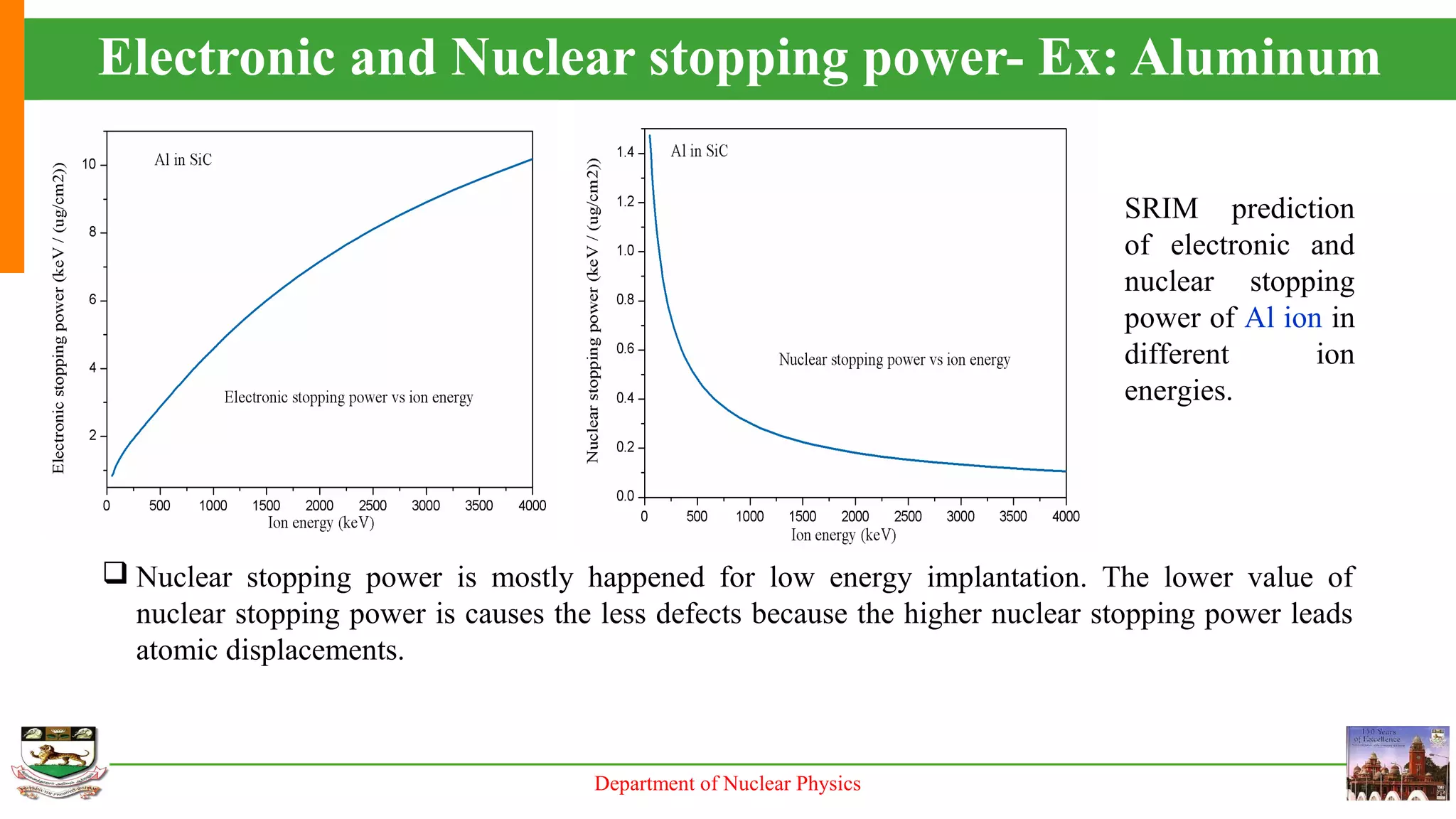
Electronic stopping- Dominant at higher
energies (tens of MeV & more)- Swift Heavy
ion irradiation (SHI)
Nuclear stopping- Dominant at low energies
(tens of keV to MeV)](https://image.slidesharecdn.com/implantation-srimtrim-160229134959/75/Implantation-srim-trim-6-2048.jpg)


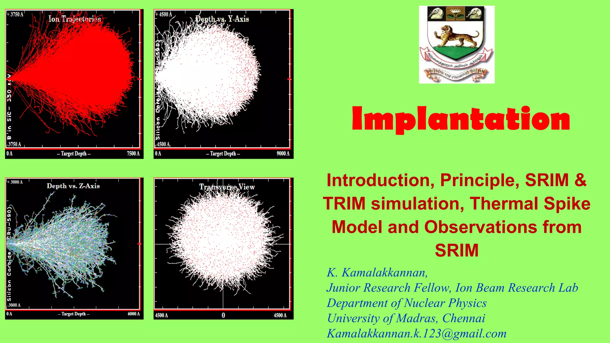
This document discusses ion implantation, which involves accelerating ions into a solid material to modify its properties. It describes the basic ion implantation process and components. SRIM and TRIM software are introduced for simulating ion implantation, allowing calculation of ion range, energy loss mechanisms, and damage within materials. Key outputs from the simulations include ion range profiles, damage distributions, and recoil energies. The document provides examples of simulation results for various ion species and implant conditions in materials like silicon carbide.


