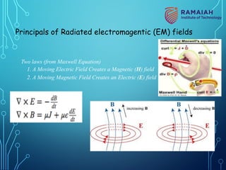
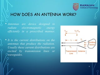
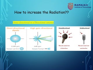
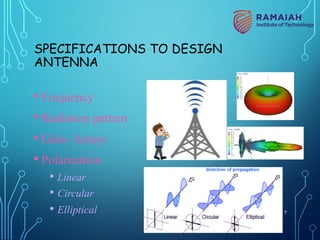
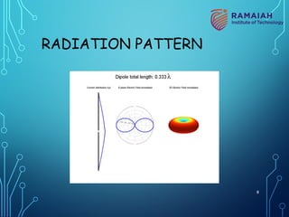
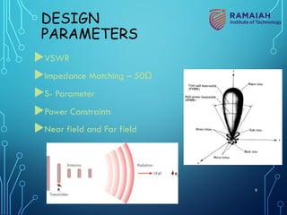
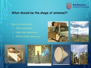
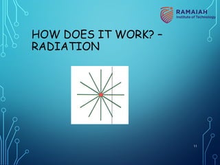
ANTENNA
DESIGN AND
DEVELOPMENT
DR.SWETHA AMIT,
ASSISTANT PROFESSOR,
DEPT OF ELECTRONICS &
TELECOMMUNICATION ENGG,
RAMAIAH INSTITUTE OF TECHNOLOGY,
BANGALORE
AGENDA
vWhat is antenna?
vWorking of antenna
vSpecifications
vParameters related to antenna design
vOverview of micro-strip antennas
v Feeding methods
v Basic principles of operation
vDesign of a Patch antenna in HFSS 2
WHAT IS AN ANTENNA??
• Device which radiates, receives radio waves.
Is Antenna Active Or Passive Device
Also,
Accentuate the radiation energy in
some directions and suppress it in
others
Hence,
antenna must also serve as a directional
device in addition to a probing device.
3
Principals of Radiated electromagentic (EM) fields
Two laws (from Maxwell Equation)
1. A Moving Electric Field Creates a Magnetic (H) field
2. A Moving Magnetic Field Creates an Electric (E) field
4
HOW DOES AN ANTENNA WORK?
• Antennas are device designed to
radiate electromagnetic energy
efficiently in a prescribed manner.
• It is the current distributions on the
antennas that produce the radiation.
Usually these current distributions are
excited by transmission lines or
waveguides.
5
Omni-directional to a Directional antenna
How to increase the Radiation??
6
SPECIFICATIONS TO DESIGN
ANTENNA
• Frequency
• Radiation pattern
• Gain- Arrays
• Polarization
• Linear
• Circular
• Elliptical 7
RADIATION PATTERN
8
DESIGN
PARAMETERS
uVSWR
uImpedance Matching – 50Ω
uS- Parameter
uPower Constraints
uNear field and Far field
9
Ø Types of antennas
Ø Wire antenna
Ø Aperture antenna
Ø Micro-strip antenna
What should be the shape of antenna??
10
HOW DOES IT WORK? –
RADIATION
11
HOW DOES IT WORK? –
RADIATION
12
HOW DOES IT WORK? –
RADIATION
13
HOW DOES IT WORK? –
RADIATION
14
HOW DOES IT WORK? –
RADIATION
B
A
Sphere grows with
time (i.e. delay
increases with
distance)
15
HOW DOES IT WORK? –
RADIATION
16
HOW DOES IT WORK? –
RADIATION
17
ANTENNAS –
TV AERIAL
•Radiation of power in space can be
controlled by carefully arranging the
patterns of electron motion
•This is the same as their sensitivity to
received signals from different
directions in space
18
FREQUENCY SELECTION
uResonant
uUWB
uMulti-resonant
Which is more
advantageous in
Mobile
Communication??? 19
20
Polarization
• EM field is composed of electric & magnetic lines of force that are
orthogonal to each other
• E determines the direction of polarization of the wave
vertical polarization: electric force lines lie in a vertical direction
horizontal polarization : electric force lines lie in a horizontal
direction
circular polarization: electric force lines rotate 360° every cycle
Polarization
21
Directivity & beam width
• acceptable lobes
• maximum gain
• bandwidth
• radiation angle
Bandwidth Issues
High Bandwidth Antennas tend to have less gain than
narrowband antennas
Narrowband Receive Antenna reduces interference from adjacent
signals & reduce received noise power
Main Trade-offs for Antenna Design
22
FRIIS TRANSMISSION FORMULA
23
NEAR FIELD/FAR FIELD
24
DAY 2
MICROSTRIP
ANTENNA
25
ANTENNA IN CELLPHONES
26
PLANAR STRUCTURES
27
MICROSTRIP LINES
28
STRIPLINES
29
DIFFERENCE BETWEEN MICROSTRIP
AND STRIPLINE
30
DIFFERENCE BETWEEN MICROSTRIP
AND STRIPLINE
31
MICROSTRIP ANTENNAS
32
MICROSTRIP ANTENNAS
33
WORKING
34
RADIATION MECHANISM
35
EQUATIONS
36
EQUATIONS
37
EQUATIONS
38
EQUATIONS
39
CALCULATIONS FOR A CHOSEN FREQUENCY
Frequency 2.4GHz
FR-4 : dielectric constant : 4.4
Thickness : 1.57mm
40
Hammerstad formula:
( )
( )
0.3 0.264
/ 0.412
0.258 0.8
eff
r
eff
r
W
h
L h
W
h
e
e
é ù
æ ö
+ +
ç ÷
ê ú
è ø
ê ú
D =
æ ö
ê ú
- +
ç ÷
ê ú
è ø
ë û
1/2
1 1
1 12
2 2
eff r r
r
h
W
e e
e
-
é ù
+ -
æ ö æ ö
= + + ç ÷
ç ÷ê ú
è ø
è øë û
Note: Even though the Hammerstad formula
involves an effective permittivity, we still use
the actual substrate permittivity in the resonance
frequency formula.
10
1
2
2 r
c
f
L L
e
æ ö
= ç ÷
+ D
è ø
Basic Principles of Operation
Resonance Frequency of Dominant Mode
41
Note: 0.5
L h
D »
This is a good “rule of thumb” to give a quick estimate.
Resonance Frequency of Dominant Mode
42
Overview of Microstrip Antennas
Also called “patch antennas”
§ One of the most useful antennas at microwave frequencies (f > 1 GHz).
§ It usually consists of a metal “patch” on top of a grounded dielectric
substrate.
§ The patch may be in a variety of shapes, but rectangular and circular
are the most common.
Microstrip line feed Coax feed
43
Common Shapes
Rectangular Square Circular
Elliptical
Annular ring
Triangular
44
x
y
h
L
W
Note: The width W is usually chosen to be larger than
L (to get higher bandwidth). However, usually W < 2L
(to avoid problems with the (0,2) mode).
er
Rectangular patch
W = 1.5L is typical.
Js
Note:
The fields and current
are approximately
independent of y for the
dominant (1,0) mode.
45
Circular Patch
x
y
h
a
er
The location of the feed determines the direction of current
flow and hence the polarization of the radiated field. 46
Advantages of Microstrip Antennas
Ø Low profile (can even be “conformal,” i.e. flexible to conform to
a surface).
Ø Easy to fabricate (use etching and photolithography).
Ø Easy to feed (coaxial cable, microstrip line, etc.).
Ø Easy to incorporate with other microstrip circuit elements and
integrate into systems.
Ø Patterns are somewhat hemispherical, with a moderate directivity
(about 6-8 dB is typical).
Ø Easy to use in an array to increase the directivity.
Ø Mechanically robust
47
Disadvantages of Microstrip Antennas
Ø Low bandwidth. Bandwidth is roughly proportional to the substrate
thickness and inversely proportional to the substrate permittivity.
Ø Efficiency may be lower than with other antennas. Efficiency is limited
by conductor and dielectric losses*, and by surface-wave loss**.
Ø Cannot handle extremely large amounts of power (dielectric
breakdown).
* Conductor and dielectric losses become more severe for thinner substrates.
** Surface-wave losses become more severe for thicker substrates (unless air or
foam is used).
48
Applications
§ Satellite communications
§ Microwave communications
§ Cell phone antennas
§ GPS antennas
49
Microstrip Antenna Integrated into a System: HIC Antenna Base-Station for 28-43 GHz
Filter
Diplexer
LNA
PD
K-connector
DC supply Micro-D
connector
Microstrip
antenna
Fiber input with
collimating lens
(Photo courtesy of Dr. Rodney B. Waterhouse)
50
Arrays
Linear array (1-D corporate feed)
2´2 array
2-D 8X8 corporate-fed array 4 ´ 8 corporate-fed / series-fed array
51
ARRAY OF POINT SOURCE
52
Wraparound Array (conformal)
The substrate is so thin that it can be bent to “conform” to the surface.
53
Coaxial Feed
Note:
A feed along the centerline at y = W/2
is the most common
(this minimizes higher-order modes
and cross-pol).
x
y
L
W
Feed at (x0, y0)
Surface current
x
r
e h
z
Feeding Methods
54
Advantages:
Ø Simple
Ø Allows for planar feeding
Ø Easy to use with arrays
Ø Easy to obtain input match
Disadvantages:
Ø Significant line radiation for thicker substrates
Ø For deep notches, patch current and radiation pattern may show distortion
Inset Feed
Microstrip line
55
Advantages:
Ø Allows for planar feeding
Ø Less line radiation compared to microstrip feed
Ø Can allow for higher bandwidth (no probe inductance, so
substrate can be thicker)
Disadvantages:
Ø Requires multilayer fabrication
Ø Alignment is important for input match
Patch
Microstrip line
Proximity-coupled Feed
(Electromagnetically-coupled Feed)
Top view
Microstrip
line
56
Advantages:
Ø Allows for planar feeding
Ø Feed-line radiation is isolated from patch radiation
Ø Higher bandwidth is possible since probe inductance is
eliminated (allowing for a thick substrate), and also a double-
resonance can be created
Ø Allows for use of different substrates to optimize antenna and
feed-circuit performance
Disadvantages:
Ø Requires multilayer fabrication
Ø Alignment is important for input match
Patch
Microstrip line
Slot
Aperture-coupled Patch (ACP)
Top view
Slot
Microstrip
line
57
Comparison of feeds
58
Ø Surface-wave power is more important for thicker substrates or for
higher-substrate permittivities. (The surface-wave power can be
minimized by using a thin substrate or a foam substrate.)
§ For a foam substrate, a high radiation efficiency is obtained
by making the substrate thicker (minimizing the conductor
and dielectric losses). There is no surface-wave power to
worry about.
§ For a typical substrate such as er = 2.2, the radiation
efficiency is maximum for h / l0 » 0.02.
Radiation Efficiency (cont.)
59
x
y
L
W
E plane
H plane
Edge diffraction is the most serious in the E plane.
General Characteristics
Radiation Patterns
Space wave cos
Eq f
varies as
Js
60
-90
-60
-30
0
30
60
90
120
150
180
210
240
-40
-30
-30
-20
-20
-10
-10
E-plane pattern
Red: infinite substrate and ground
plane
Blue: 1 meter
ground plane
Note: The E-plane pattern “tucks
in” and tends to zero at the
horizon due to the presence of
the infinite substrate.
Radiation Patterns
61
Red: infinite
substrate and
ground plane
Blue: 1 meter
ground plane
-90
-45
0
45
90
135
180
225
-40
-30
-30
-20
-20
-10
-10
H-plane pattern
Radiation Patterns
62
Directivity
ØThe directivity is fairly insensitive to the substrate
thickness.
ØThe directivity is higher for lower permittivity,
because the patch is larger.
63
ANTENNA DESIGN APPROACH
64
65
ANTENNAS DESIGNED IN HFSS
• Patch Antenna : Rectangular, Triangular,Circular
• Wearable Antenna/ Textile Antenna
• Wearable Metamaterial Reflectors
• Metamaterial Radomes
• Frequency Selective Surface structures in wearable devices
• SAR analysis on Human phantom for the designed antenna
• MIMO antenna
• Fractal Antenna (Sierpienski, spidron arm)
• Liquid Antenna
PUBLICATIONS BY USING HFSS
1. Swetha Amit, T R Ramya, Vandana S, Pooja C R, “Ultra Wide Band Symmetric Slots Antenna for Wearable
Applications”, IEEE 4th International Conference on Communication and Electronics Systems (ICCES 2019),
July 17-19, 2019, PPG Institute of Technology, Coimbatore, India. [Scopus Indexed]
2. Swetha Amit, Viswanath Talasila, Prasad Shastry, “A Semi-Circular Slot Textile Antenna for Ultra-Wideband
Applications”, 2019 IEEE International Symposium on Antennas and Propagation and USNC-URSI Radio
Science Meeting, Atlanta, Georgia, USA, 7-12 July 2019. pp. 249-250. [SJR Indexed] DOI:
10.1109/APUSNCURSINRSM.2019.8889148
3. Ashwini K S, Panchami Prabhu, Shreyas S Nayak, Swetha Amit, “Miniaturised rectangular patch antenna using
defected ground plane”, 5th National Conference on Advancements in Information Technology NCAIT-2019, 10th
and 11th April 2019, JSS Academy of Technical Education, Bangalore.
4. Rakshan T A, Syed Fauzan, Swetha Amit, “Study and Analysis in reduction of Specific Absorption Rate (SAR) in
Human body using Wearable Antenna for BAN Applications”, 2019 4th IEEE International Conference on
Recent Trends on Electronics, Information, Communication & Technology (RTEICT-2019), MAY 17th & 18th
2019. [Scopus Indexed]
5. Sreepriya S, Nikhil George, Dr.Swetha Amit, “A Multi-Resonant Microstrip Patch Antenna with Fractal Defected
Ground Structure”, IEEE First International Conference on Advanced Technologies in Intelligent Control,
Environment, Computing & Communication Engineering (ICATIECE-2019), 19th and 20th March 2019,
Bangalore, India [Scopus Indexed]
6. Akshay K M, Swetha Amit , “Analysis and Design of a Phased Array Antenna using Circular
Microstrip Patch Elements with BST Technology for X-band Application”, 11th International
Conference- Antenna Test & Measurement Society ( ATMS), 5th to 7th February 2018, Pune, India.
7. Divyashree J, Ashlesha Bhalare Shivananda, Swetha Amit, “Design and Development of
Metamaterial Antennas on different Substrates for its Performance Evaluation”, 11th International
Conference- Antenna Test & Measurement Society ( ATMS), 5th to 7th February 2018, Pune, India.
8. Pallavi T N, Mala J, Swetha Amit , “Analysis and design of Hexagonal Shape Fractal Wideband
Antenna”, 11th International Conference- Antenna Test & Measurement Society (ATMS), 5th to 7th
February 2018, Pune, India.
9. Swetha Amit, Oshin S P, “Design, Implementation and Performance analysis of a high gain UWB
Slot Wearable Antenna with Human Phantom for Medical Application”, 2017 IEEE International
Conference on Antenna Innovations & Modern Technologies for Ground, Aircraft and Satellite
Applications (iAIM), 24th to 27th November, 2017, Bangalore DOI: 10.1109/IAIM.2017.8402601
[Scopus indexed] .
https://ieeexplore.ieee.org/stamp/stamp.jsp?tp=&arnumber=8402601&isnumber=8402513&tag=1
PUBLICATIONS BY USING HFSS
10.Oshin S P, Swetha Amit, “Design and analysis high gain UWB textile Antenna for wearable applications”, IEEE
International Conference on Recent Trends in Electronics Information Communication Technology (RTEICT-
2017), Bangalore, May 2017, INDIA DOI: 10.1109/RTEICT.2017.8256585 [Scopus indexed]
11. Swetha Amit, Nisha S L, “Design and Development of Printed Dipole Antenna with Array Configuration for
GPS application”, IEEE 2016 International Conference on Circuits, Controls, Communications and Computing
(I4C), 4th to 6th October 2016 at M S Ramaiah Institute of Technology, Bangalore.
DOI: 10.1109/CIMCA.2016.8053279 [Scopus indexed]
12. Thalath Farheen Khanum, Swetha Amit, “A compact Wideband Sierpinski Antenna loaded with Metamaterial”,
IEEE 2016 International Conference on Electrical, Electronics, and Optimization Techniques (ICEEOT), DMJ
College of Engineering, Chennai, Tamil Nadu, India during 3rd to 5th March 2016.
DOI: 10.1109/ICEEOT.2016.7755338 [Scopus indexed]
13. Thalath Farheen Khanum, Swetha Amit, “ Design and Analysis of Multiband Symmetrical MLA with Fractal
Metamaterial “IEEE 2016 International Conference on Electrical, Electronics, and Optimization Techniques
(ICEEOT), DMJ College of Engineering, Chennai, Tamil Nadu, India during 3rd to 5th March 2016.
DOI: 10.1109/ICEEOT.2016.7755204 [Scopus indexed]
14. Thalath Farheen Khanum, Swetha Amit, “Design and Simulation of Symmetrical MLA-PIFA with
Metamaterial", 2016 IEEE International Conference on Recent Trends in Electronics, Information &
Communication Technology (RTEICT), Sri Venkateshwara college of Engineering, Bangalore, Karnataka ,India
during 20th and 21st May-2016. DOI: 10.1109/RTEICT.2016.7808006
PUBLICATIONS BY USING HFSS
16. Swetha Amit, "Design of compact bent dipole antenna and its array with high gain
performance for GPS application," 2016 8th International Conference on Communication Systems
and Networks (COMSNETS), 5th to 10th January 2016, Bangalore, India.
DOI:10.1109/COMSNETS.2016.7439935 [Scopus indexed]
17. Swetha Amit, Chinmoy Kumar P R, Nayana Arvind Laxmeshwar, Saurabh R Badenkal, “A
Spidron Fractal Array Antenna with Enhanced Impedance Matching for Multiple Frequencies”,
IEEE International Conference on IMPact of E-Technology on US (IEEE IC-IMPETUS), 10th and
11th January, 2014.
18. Swetha Amit, Chinmoy Kumar P R, Nayana Arvind Laxmeshwar, Saurabh R Badenkal, “A
Novel Swastik Shaped Spidron Fractal Array Antenna for S-Band Applications”, 7th International
Conference, Antenna Test and Measurement Society (ATMS), INDIA, 11th and 12th February
2014, Chennai.
19. Swetha Amit, Chinmoy Kumar P R, Nayana Arvind Laxmeshwar, Saurabh R Badenkal, “A
Spidron Fractal Antenna with Enhanced Impedance Matching for Wideband Applications”, 9th
International Conference on Microwaves, Antenna, Propagation and Remote sensing (ICMARS)
December 11th to 14th 2013, International Center for Radio Sciences, Jodhpur, Rajasthan, India.
PUBLICATIONS BY USING HFSS
20. Swetha Amit, “A Flexible Low Profile Symmetric Slots Antenna for Wearable Applications”, Control and Data
Fusion e-Journal: CADFEJL Vol. 2, No. 4, pp. 32-37, Jul-Aug 2018. ISSN: 2581-5490.
https://www.cadfejl.com/phocadownload/CADF%20JulAug%202018%2003%20SA%20Antenna.pdf
21. Swetha Amit, “Design and Implementation of Printed Folded Dipole Antenna for GPS Application”,
International Journal for Scientific Research and Development (IJSRD), Volume 3, Issue 5, July 2015, ISSN:
23210613. http://www.ijsrd.com/articles/IJSRDV3I50181.pdf
22. Kadam Astik M, Swetha Amit, “Design and Implementation of Quasi Landstorfer Antenna for Wireless
Communication”, International Research Journal of Engineering and Technology (IRJET), Volume 2 Issue 4,
July 2015, e-ISSN: 2395-0056, p-ISSN: 2395-0072. https://www.irjet.net/volume-2-issue-4
23. Sangeetha.G, Swetha Amit, “Design and implementation of Novel Nine shaped MIMO Antenna for LTE
Applications”, International Journal of Advanced Research in Computer and Communication Engineering
(IJARCCE), Vol. 3, Issue 5, May 2014, ISSN : 2278-1021, PP : 2319-5940. https://ijarcce.com/wp-
content/uploads/2012/03/IJARCCE5E-a-swetha-amit-Design-and-implementation.pdf
24. Sangeetha.G, Swetha Amit, “Design of a Novel Nine Shaped Tri-Band MIMO Antenna for LTE
Applications”, International Journal of Innovative Research in Technology & Science(IJIRTS), Vol. 2, Issue 3,
May 2014, ISSN:2321-1156. http://ijirts.org/volume2issue3/IJIRTSV2I3054.pdf
PUBLICATIONS BY USING HFSS
ANY QUERIES:
PLEASE REACH ME @
SWETHA.AMIT@GMAIL.COM

457548852-Antenna-design for -ppt-pdf.pdf

  • 1.
    ANTENNA DESIGN AND DEVELOPMENT DR.SWETHA AMIT, ASSISTANTPROFESSOR, DEPT OF ELECTRONICS & TELECOMMUNICATION ENGG, RAMAIAH INSTITUTE OF TECHNOLOGY, BANGALORE
  • 2.
    AGENDA vWhat is antenna? vWorkingof antenna vSpecifications vParameters related to antenna design vOverview of micro-strip antennas v Feeding methods v Basic principles of operation vDesign of a Patch antenna in HFSS 2
  • 3.
    WHAT IS ANANTENNA?? • Device which radiates, receives radio waves. Is Antenna Active Or Passive Device Also, Accentuate the radiation energy in some directions and suppress it in others Hence, antenna must also serve as a directional device in addition to a probing device. 3
  • 4.
    Principals of Radiatedelectromagentic (EM) fields Two laws (from Maxwell Equation) 1. A Moving Electric Field Creates a Magnetic (H) field 2. A Moving Magnetic Field Creates an Electric (E) field 4
  • 5.
    HOW DOES ANANTENNA WORK? • Antennas are device designed to radiate electromagnetic energy efficiently in a prescribed manner. • It is the current distributions on the antennas that produce the radiation. Usually these current distributions are excited by transmission lines or waveguides. 5
  • 6.
    Omni-directional to aDirectional antenna How to increase the Radiation?? 6
  • 7.
    SPECIFICATIONS TO DESIGN ANTENNA •Frequency • Radiation pattern • Gain- Arrays • Polarization • Linear • Circular • Elliptical 7
  • 8.
  • 9.
    DESIGN PARAMETERS uVSWR uImpedance Matching –50Ω uS- Parameter uPower Constraints uNear field and Far field 9
  • 10.
    Ø Types ofantennas Ø Wire antenna Ø Aperture antenna Ø Micro-strip antenna What should be the shape of antenna?? 10
  • 11.
    HOW DOES ITWORK? – RADIATION 11
  • 12.
    HOW DOES ITWORK? – RADIATION 12
  • 13.
    HOW DOES ITWORK? – RADIATION 13
  • 14.
    HOW DOES ITWORK? – RADIATION 14
  • 15.
    HOW DOES ITWORK? – RADIATION B A Sphere grows with time (i.e. delay increases with distance) 15
  • 16.
    HOW DOES ITWORK? – RADIATION 16
  • 17.
    HOW DOES ITWORK? – RADIATION 17
  • 18.
    ANTENNAS – TV AERIAL •Radiationof power in space can be controlled by carefully arranging the patterns of electron motion •This is the same as their sensitivity to received signals from different directions in space 18
  • 19.
    FREQUENCY SELECTION uResonant uUWB uMulti-resonant Which ismore advantageous in Mobile Communication??? 19
  • 20.
  • 21.
    • EM fieldis composed of electric & magnetic lines of force that are orthogonal to each other • E determines the direction of polarization of the wave vertical polarization: electric force lines lie in a vertical direction horizontal polarization : electric force lines lie in a horizontal direction circular polarization: electric force lines rotate 360° every cycle Polarization 21
  • 22.
    Directivity & beamwidth • acceptable lobes • maximum gain • bandwidth • radiation angle Bandwidth Issues High Bandwidth Antennas tend to have less gain than narrowband antennas Narrowband Receive Antenna reduces interference from adjacent signals & reduce received noise power Main Trade-offs for Antenna Design 22
  • 23.
  • 24.
  • 25.
  • 26.
  • 27.
  • 28.
  • 29.
  • 30.
  • 31.
  • 32.
  • 33.
  • 34.
  • 35.
  • 36.
  • 37.
  • 38.
  • 39.
  • 40.
    CALCULATIONS FOR ACHOSEN FREQUENCY Frequency 2.4GHz FR-4 : dielectric constant : 4.4 Thickness : 1.57mm 40
  • 41.
    Hammerstad formula: ( ) () 0.3 0.264 / 0.412 0.258 0.8 eff r eff r W h L h W h e e é ù æ ö + + ç ÷ ê ú è ø ê ú D = æ ö ê ú - + ç ÷ ê ú è ø ë û 1/2 1 1 1 12 2 2 eff r r r h W e e e - é ù + - æ ö æ ö = + + ç ÷ ç ÷ê ú è ø è øë û Note: Even though the Hammerstad formula involves an effective permittivity, we still use the actual substrate permittivity in the resonance frequency formula. 10 1 2 2 r c f L L e æ ö = ç ÷ + D è ø Basic Principles of Operation Resonance Frequency of Dominant Mode 41
  • 42.
    Note: 0.5 L h D» This is a good “rule of thumb” to give a quick estimate. Resonance Frequency of Dominant Mode 42
  • 43.
    Overview of MicrostripAntennas Also called “patch antennas” § One of the most useful antennas at microwave frequencies (f > 1 GHz). § It usually consists of a metal “patch” on top of a grounded dielectric substrate. § The patch may be in a variety of shapes, but rectangular and circular are the most common. Microstrip line feed Coax feed 43
  • 44.
    Common Shapes Rectangular SquareCircular Elliptical Annular ring Triangular 44
  • 45.
    x y h L W Note: The widthW is usually chosen to be larger than L (to get higher bandwidth). However, usually W < 2L (to avoid problems with the (0,2) mode). er Rectangular patch W = 1.5L is typical. Js Note: The fields and current are approximately independent of y for the dominant (1,0) mode. 45
  • 46.
    Circular Patch x y h a er The locationof the feed determines the direction of current flow and hence the polarization of the radiated field. 46
  • 47.
    Advantages of MicrostripAntennas Ø Low profile (can even be “conformal,” i.e. flexible to conform to a surface). Ø Easy to fabricate (use etching and photolithography). Ø Easy to feed (coaxial cable, microstrip line, etc.). Ø Easy to incorporate with other microstrip circuit elements and integrate into systems. Ø Patterns are somewhat hemispherical, with a moderate directivity (about 6-8 dB is typical). Ø Easy to use in an array to increase the directivity. Ø Mechanically robust 47
  • 48.
    Disadvantages of MicrostripAntennas Ø Low bandwidth. Bandwidth is roughly proportional to the substrate thickness and inversely proportional to the substrate permittivity. Ø Efficiency may be lower than with other antennas. Efficiency is limited by conductor and dielectric losses*, and by surface-wave loss**. Ø Cannot handle extremely large amounts of power (dielectric breakdown). * Conductor and dielectric losses become more severe for thinner substrates. ** Surface-wave losses become more severe for thicker substrates (unless air or foam is used). 48
  • 49.
    Applications § Satellite communications §Microwave communications § Cell phone antennas § GPS antennas 49
  • 50.
    Microstrip Antenna Integratedinto a System: HIC Antenna Base-Station for 28-43 GHz Filter Diplexer LNA PD K-connector DC supply Micro-D connector Microstrip antenna Fiber input with collimating lens (Photo courtesy of Dr. Rodney B. Waterhouse) 50
  • 51.
    Arrays Linear array (1-Dcorporate feed) 2´2 array 2-D 8X8 corporate-fed array 4 ´ 8 corporate-fed / series-fed array 51
  • 52.
    ARRAY OF POINTSOURCE 52
  • 53.
    Wraparound Array (conformal) Thesubstrate is so thin that it can be bent to “conform” to the surface. 53
  • 54.
    Coaxial Feed Note: A feedalong the centerline at y = W/2 is the most common (this minimizes higher-order modes and cross-pol). x y L W Feed at (x0, y0) Surface current x r e h z Feeding Methods 54
  • 55.
    Advantages: Ø Simple Ø Allowsfor planar feeding Ø Easy to use with arrays Ø Easy to obtain input match Disadvantages: Ø Significant line radiation for thicker substrates Ø For deep notches, patch current and radiation pattern may show distortion Inset Feed Microstrip line 55
  • 56.
    Advantages: Ø Allows forplanar feeding Ø Less line radiation compared to microstrip feed Ø Can allow for higher bandwidth (no probe inductance, so substrate can be thicker) Disadvantages: Ø Requires multilayer fabrication Ø Alignment is important for input match Patch Microstrip line Proximity-coupled Feed (Electromagnetically-coupled Feed) Top view Microstrip line 56
  • 57.
    Advantages: Ø Allows forplanar feeding Ø Feed-line radiation is isolated from patch radiation Ø Higher bandwidth is possible since probe inductance is eliminated (allowing for a thick substrate), and also a double- resonance can be created Ø Allows for use of different substrates to optimize antenna and feed-circuit performance Disadvantages: Ø Requires multilayer fabrication Ø Alignment is important for input match Patch Microstrip line Slot Aperture-coupled Patch (ACP) Top view Slot Microstrip line 57
  • 58.
  • 59.
    Ø Surface-wave poweris more important for thicker substrates or for higher-substrate permittivities. (The surface-wave power can be minimized by using a thin substrate or a foam substrate.) § For a foam substrate, a high radiation efficiency is obtained by making the substrate thicker (minimizing the conductor and dielectric losses). There is no surface-wave power to worry about. § For a typical substrate such as er = 2.2, the radiation efficiency is maximum for h / l0 » 0.02. Radiation Efficiency (cont.) 59
  • 60.
    x y L W E plane H plane Edgediffraction is the most serious in the E plane. General Characteristics Radiation Patterns Space wave cos Eq f varies as Js 60
  • 61.
    -90 -60 -30 0 30 60 90 120 150 180 210 240 -40 -30 -30 -20 -20 -10 -10 E-plane pattern Red: infinitesubstrate and ground plane Blue: 1 meter ground plane Note: The E-plane pattern “tucks in” and tends to zero at the horizon due to the presence of the infinite substrate. Radiation Patterns 61
  • 62.
    Red: infinite substrate and groundplane Blue: 1 meter ground plane -90 -45 0 45 90 135 180 225 -40 -30 -30 -20 -20 -10 -10 H-plane pattern Radiation Patterns 62
  • 63.
    Directivity ØThe directivity isfairly insensitive to the substrate thickness. ØThe directivity is higher for lower permittivity, because the patch is larger. 63
  • 64.
  • 65.
    65 ANTENNAS DESIGNED INHFSS • Patch Antenna : Rectangular, Triangular,Circular • Wearable Antenna/ Textile Antenna • Wearable Metamaterial Reflectors • Metamaterial Radomes • Frequency Selective Surface structures in wearable devices • SAR analysis on Human phantom for the designed antenna • MIMO antenna • Fractal Antenna (Sierpienski, spidron arm) • Liquid Antenna
  • 66.
    PUBLICATIONS BY USINGHFSS 1. Swetha Amit, T R Ramya, Vandana S, Pooja C R, “Ultra Wide Band Symmetric Slots Antenna for Wearable Applications”, IEEE 4th International Conference on Communication and Electronics Systems (ICCES 2019), July 17-19, 2019, PPG Institute of Technology, Coimbatore, India. [Scopus Indexed] 2. Swetha Amit, Viswanath Talasila, Prasad Shastry, “A Semi-Circular Slot Textile Antenna for Ultra-Wideband Applications”, 2019 IEEE International Symposium on Antennas and Propagation and USNC-URSI Radio Science Meeting, Atlanta, Georgia, USA, 7-12 July 2019. pp. 249-250. [SJR Indexed] DOI: 10.1109/APUSNCURSINRSM.2019.8889148 3. Ashwini K S, Panchami Prabhu, Shreyas S Nayak, Swetha Amit, “Miniaturised rectangular patch antenna using defected ground plane”, 5th National Conference on Advancements in Information Technology NCAIT-2019, 10th and 11th April 2019, JSS Academy of Technical Education, Bangalore. 4. Rakshan T A, Syed Fauzan, Swetha Amit, “Study and Analysis in reduction of Specific Absorption Rate (SAR) in Human body using Wearable Antenna for BAN Applications”, 2019 4th IEEE International Conference on Recent Trends on Electronics, Information, Communication & Technology (RTEICT-2019), MAY 17th & 18th 2019. [Scopus Indexed] 5. Sreepriya S, Nikhil George, Dr.Swetha Amit, “A Multi-Resonant Microstrip Patch Antenna with Fractal Defected Ground Structure”, IEEE First International Conference on Advanced Technologies in Intelligent Control, Environment, Computing & Communication Engineering (ICATIECE-2019), 19th and 20th March 2019, Bangalore, India [Scopus Indexed]
  • 67.
    6. Akshay KM, Swetha Amit , “Analysis and Design of a Phased Array Antenna using Circular Microstrip Patch Elements with BST Technology for X-band Application”, 11th International Conference- Antenna Test & Measurement Society ( ATMS), 5th to 7th February 2018, Pune, India. 7. Divyashree J, Ashlesha Bhalare Shivananda, Swetha Amit, “Design and Development of Metamaterial Antennas on different Substrates for its Performance Evaluation”, 11th International Conference- Antenna Test & Measurement Society ( ATMS), 5th to 7th February 2018, Pune, India. 8. Pallavi T N, Mala J, Swetha Amit , “Analysis and design of Hexagonal Shape Fractal Wideband Antenna”, 11th International Conference- Antenna Test & Measurement Society (ATMS), 5th to 7th February 2018, Pune, India. 9. Swetha Amit, Oshin S P, “Design, Implementation and Performance analysis of a high gain UWB Slot Wearable Antenna with Human Phantom for Medical Application”, 2017 IEEE International Conference on Antenna Innovations & Modern Technologies for Ground, Aircraft and Satellite Applications (iAIM), 24th to 27th November, 2017, Bangalore DOI: 10.1109/IAIM.2017.8402601 [Scopus indexed] . https://ieeexplore.ieee.org/stamp/stamp.jsp?tp=&arnumber=8402601&isnumber=8402513&tag=1 PUBLICATIONS BY USING HFSS
  • 68.
    10.Oshin S P,Swetha Amit, “Design and analysis high gain UWB textile Antenna for wearable applications”, IEEE International Conference on Recent Trends in Electronics Information Communication Technology (RTEICT- 2017), Bangalore, May 2017, INDIA DOI: 10.1109/RTEICT.2017.8256585 [Scopus indexed] 11. Swetha Amit, Nisha S L, “Design and Development of Printed Dipole Antenna with Array Configuration for GPS application”, IEEE 2016 International Conference on Circuits, Controls, Communications and Computing (I4C), 4th to 6th October 2016 at M S Ramaiah Institute of Technology, Bangalore. DOI: 10.1109/CIMCA.2016.8053279 [Scopus indexed] 12. Thalath Farheen Khanum, Swetha Amit, “A compact Wideband Sierpinski Antenna loaded with Metamaterial”, IEEE 2016 International Conference on Electrical, Electronics, and Optimization Techniques (ICEEOT), DMJ College of Engineering, Chennai, Tamil Nadu, India during 3rd to 5th March 2016. DOI: 10.1109/ICEEOT.2016.7755338 [Scopus indexed] 13. Thalath Farheen Khanum, Swetha Amit, “ Design and Analysis of Multiband Symmetrical MLA with Fractal Metamaterial “IEEE 2016 International Conference on Electrical, Electronics, and Optimization Techniques (ICEEOT), DMJ College of Engineering, Chennai, Tamil Nadu, India during 3rd to 5th March 2016. DOI: 10.1109/ICEEOT.2016.7755204 [Scopus indexed] 14. Thalath Farheen Khanum, Swetha Amit, “Design and Simulation of Symmetrical MLA-PIFA with Metamaterial", 2016 IEEE International Conference on Recent Trends in Electronics, Information & Communication Technology (RTEICT), Sri Venkateshwara college of Engineering, Bangalore, Karnataka ,India during 20th and 21st May-2016. DOI: 10.1109/RTEICT.2016.7808006 PUBLICATIONS BY USING HFSS
  • 69.
    16. Swetha Amit,"Design of compact bent dipole antenna and its array with high gain performance for GPS application," 2016 8th International Conference on Communication Systems and Networks (COMSNETS), 5th to 10th January 2016, Bangalore, India. DOI:10.1109/COMSNETS.2016.7439935 [Scopus indexed] 17. Swetha Amit, Chinmoy Kumar P R, Nayana Arvind Laxmeshwar, Saurabh R Badenkal, “A Spidron Fractal Array Antenna with Enhanced Impedance Matching for Multiple Frequencies”, IEEE International Conference on IMPact of E-Technology on US (IEEE IC-IMPETUS), 10th and 11th January, 2014. 18. Swetha Amit, Chinmoy Kumar P R, Nayana Arvind Laxmeshwar, Saurabh R Badenkal, “A Novel Swastik Shaped Spidron Fractal Array Antenna for S-Band Applications”, 7th International Conference, Antenna Test and Measurement Society (ATMS), INDIA, 11th and 12th February 2014, Chennai. 19. Swetha Amit, Chinmoy Kumar P R, Nayana Arvind Laxmeshwar, Saurabh R Badenkal, “A Spidron Fractal Antenna with Enhanced Impedance Matching for Wideband Applications”, 9th International Conference on Microwaves, Antenna, Propagation and Remote sensing (ICMARS) December 11th to 14th 2013, International Center for Radio Sciences, Jodhpur, Rajasthan, India. PUBLICATIONS BY USING HFSS
  • 70.
    20. Swetha Amit,“A Flexible Low Profile Symmetric Slots Antenna for Wearable Applications”, Control and Data Fusion e-Journal: CADFEJL Vol. 2, No. 4, pp. 32-37, Jul-Aug 2018. ISSN: 2581-5490. https://www.cadfejl.com/phocadownload/CADF%20JulAug%202018%2003%20SA%20Antenna.pdf 21. Swetha Amit, “Design and Implementation of Printed Folded Dipole Antenna for GPS Application”, International Journal for Scientific Research and Development (IJSRD), Volume 3, Issue 5, July 2015, ISSN: 23210613. http://www.ijsrd.com/articles/IJSRDV3I50181.pdf 22. Kadam Astik M, Swetha Amit, “Design and Implementation of Quasi Landstorfer Antenna for Wireless Communication”, International Research Journal of Engineering and Technology (IRJET), Volume 2 Issue 4, July 2015, e-ISSN: 2395-0056, p-ISSN: 2395-0072. https://www.irjet.net/volume-2-issue-4 23. Sangeetha.G, Swetha Amit, “Design and implementation of Novel Nine shaped MIMO Antenna for LTE Applications”, International Journal of Advanced Research in Computer and Communication Engineering (IJARCCE), Vol. 3, Issue 5, May 2014, ISSN : 2278-1021, PP : 2319-5940. https://ijarcce.com/wp- content/uploads/2012/03/IJARCCE5E-a-swetha-amit-Design-and-implementation.pdf 24. Sangeetha.G, Swetha Amit, “Design of a Novel Nine Shaped Tri-Band MIMO Antenna for LTE Applications”, International Journal of Innovative Research in Technology & Science(IJIRTS), Vol. 2, Issue 3, May 2014, ISSN:2321-1156. http://ijirts.org/volume2issue3/IJIRTSV2I3054.pdf PUBLICATIONS BY USING HFSS
  • 71.
    ANY QUERIES: PLEASE REACHME @ SWETHA.AMIT@GMAIL.COM