Downloaded 472 times

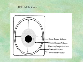
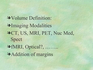
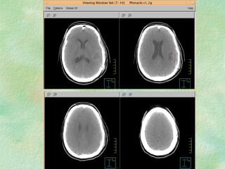
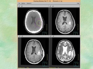
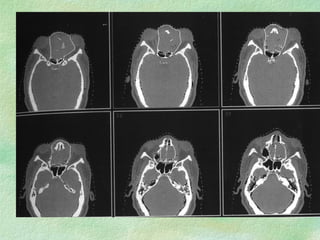
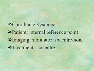
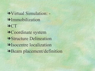
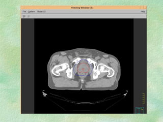
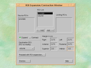
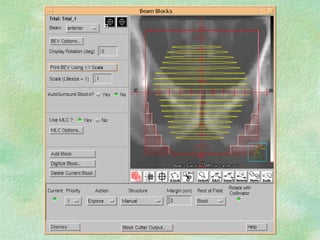
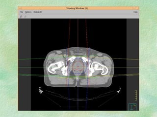
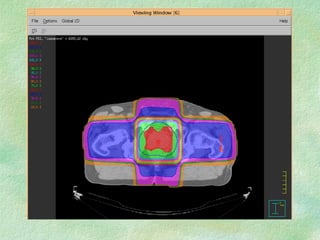
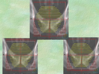
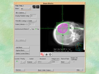

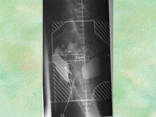
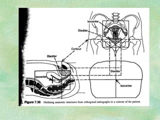
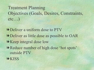
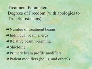
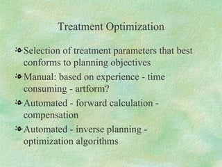
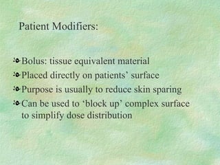
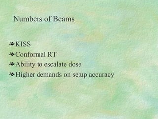
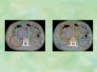
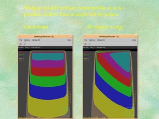
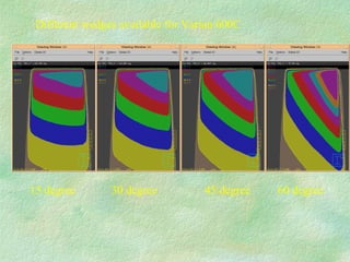
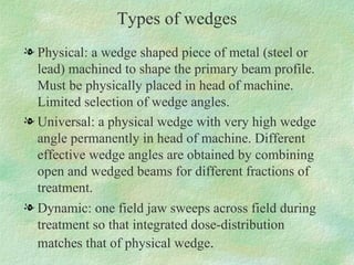
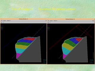
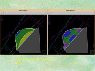
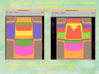
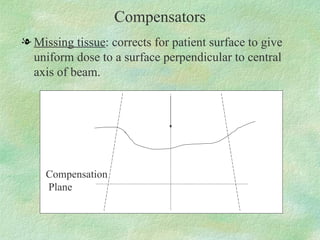
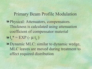
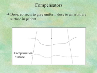


Treatment planning involves defining target volumes and organs at risk on imaging scans. Virtual simulation uses CT scans to delineate structures and localize the treatment isocenter. This allows improved volume definition compared to conventional simulation. Treatment planning optimization selects parameters like beam number, weighting, and modifiers to best conform the dose distribution to planning objectives while minimizing dose to organs at risk. Beam modifiers like wedges and compensators can be used to modify the dose distribution for target coverage and organ sparing.


![Arc therapy [autosaved] [autosaved]](https://cdn.slidesharecdn.com/ss_thumbnails/arctherapyautosavedautosaved-150423125828-conversion-gate01-thumbnail.jpg?width=640&height=640&fit=bounds)


![CTEV [ clubfoot] DR ARUN LAL ,DR MOHAMED ASHRAF travancore medical college k...](https://cdn.slidesharecdn.com/ss_thumbnails/ctevclubfootdrarunlaldrmohamedashraftravancoremedicalcollegekollamkeralaindia-260208063247-18fc466c-thumbnail.jpg?width=640&height=640&fit=bounds)


![PERI-PROSTHETIC FRACTURE NAIL-PLATE CONSTRUCT [NPC].pptx](https://cdn.slidesharecdn.com/ss_thumbnails/drarunkumardrmohamedashrafperiprostheticfrasturenail-plateconstructnpc-260209164459-7e9d15a1-thumbnail.jpg?width=640&height=640&fit=bounds)


