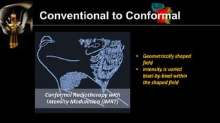
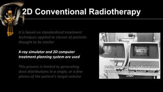
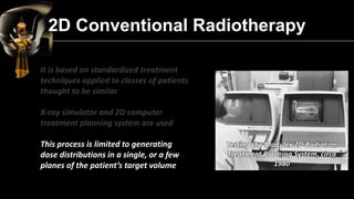
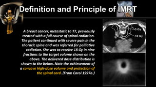
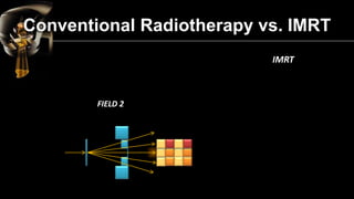
Conventional to Conformal 
2D Conventional Radiotherapy 
3D Conformal Radiotherapy 
Intensity Modulation 
IMRT – Definition and Principle 
Conventional Radiotherapy vs. IMRT 
Benefits to the Patient 
Clinical Implementation of IMRT 
IMRT – Treatment Planning 
Different IMRT Techniques 
IMRT with Multileaf Collimator 
IMRT Quality Assurance Program 
Draw Backs of IMRT 
Risk of IMRT
Conventional Radiotherapy
Conformal Radiotherapy
Intensity Modulated Radiotherapy (IMRT)
Conventional Radiotherapy 
Conventional to Conformal
Conventional to Conformal Conformal Radiotherapy without Intensity Modulation (CRT)
Conventional to Conformal 
Conformal Radiotherapy with Intensity Modulation (IMRT)
It is based on standardized treatment techniques applied to classes of patients thought to be similar 
X-ray simulator and 2D computer treatment planning system are used 
This process is limited to generating dose distributions in a single, or a few planes of the patient’s target volume 
2D Conventional Radiotherapy
It is based on standardized treatment techniques applied to classes of patients thought to be similar 
X-ray simulator and 2D computer treatment planning system are used 
This process is limited to generating dose distributions in a single, or a few planes of the patient’s target volume Testing the Modulex 2D Radiation Treatment Planning System, circa 1980 
2D Conventional Radiotherapy
2D Conventional Radiotherapy It is based on standardized treatment techniques applied to classes of patients thought to be similar X-ray simulator and 2D computer treatment planning system are used This process is limited to generating dose distributions in a single, or a few planes of the patient’s target volume 
Testing the Modulex 2D Radiation Treatment Planning System, circa 1980
2D Conventional Radiotherapy 
2D transmission images of human body provided unprecedented imagery of bony landmarks, allowing radiologists to deduce the location of internal organs 
Additional blocks placed daily to match marks on the patient’s skin 
Using planar radiographs, radiologists planned cancer treatments by collimating rectangular fields encompassing the presumed tumor location
3D Conformal Radiotherapy 
It allows to increase the doses of radiation delivered to the tumor without increasing damage to nearby tissues. 
Before treatment is begun, digital images of the individual’s target are prepared and compiled into virtual 3D models of how the target will “look” to the accelerator from all angles. 
Then the accelerator shapes the beam to match those “beam’s eye views” (insets), thus reducing the amount of radiation hitting the organs at risk or other unintended targets.
3D CRT : Treatment Planning Process 
Imaging Data Aquisition 
To accurately delineate target volume and normal structures 
CT is the most commonly used procedure, even other modalities offer special advantages in imaging certain types of tumors and locations 
CT 
MRI 
PET 
SPECT
3D CRT : Treatment Planning Process 
Image Registration 
It is a process of correlating different image data sets to identify corresponding structures or regions Image fusion is the seamless mixing up of two image sets of the same patient; it may be 
-Two different image modalities 
-Same modality in which image sets are taken at different point of time
3D CRT : Treatment Planning Process 
It refers to slice-by-slice delineation of anatomic regions of interest 
The segmented regions can be rendered in different and can be viewed in beam’s eye view (BEV) configuration or in other planes using digital reconstructed radiographs
3D CRT : Treatment Planning Process 
Designing beam aperture is aided by the BEV capability of the 3D treatment planning system
3D CRT : Treatment Planning Process 
Combination of multileaf collimators and independent jaws provides almost unlimited capability of designing multiple fields of any shape 
Targets and critical structures can be viewed in the BEV configuration individually for each field
3D CRT : Treatment Planning Process 
An optimal plan should deliver tumoricidal dose to the entire tumor and spare all the normal tissues. 
Isodose Curves and Surfaces 
Dose distributions of competing plans are evaluated by viewing isodose curves in individual slices, orthogonal planes or 3D isodose surfaces
3D CRT : Treatment Planning Process 
Dose Volume Histograms (DVHs) 
Display of dose distribution in the form of isodose curves or surfaces is useful because their anatomic location and extent. 
This information is supplemented by dose volume histograms (DVHs). 
DVH summarizes the entire dose distribution into a single curve for each anatomic structure of interest.
3D CRT : Treatment Planning Process 
Electronic Portal Imaging (EPI) 
Patient position at the time of treatment should be verifiable via electronic portal imaging (EPI) 
Tools should exist to quantify discrepancies between treatment position and planned position and to evaluate consequences and make corrections
3D CRT
Intensity Modulation 
•Conventional radiotherapy treatments are delivered with radiation beams that are of uniform intensity across the field (within the flatness specification limits) 
•Wedges or compensators are used to modify the intensity profile to offset contour in irregularities and produce more uniform composite dose distributions such as in techniques using wedges 
•This process of changing beam intensity profile to meet the goals of a composite plan is called intensity modulation
Intensity Modulation 
•Conventional radiotherapy treatments are delivered with radiation beams that are of uniform intensity across the field (within the flatness specification limits) 
•Wedges or compensators are used to modify the intensity profile to offset contour in irregularities and produce more uniform composite dose distributions such as in techniques using wedges 
•This process of changing beam intensity profile to meet the goals of a composite plan is called
IMRT refers to a radiation therapy technique in which nonuniform fluence is delivered to the patient from any given position of the treatment beam to optimize the composite dose distribution 
Definition and Principle of IMRT
The fluence files thus generated are electronically transmitted to the linear accelerator, which is computer controlled, to deliver intensity modulated beams (IMBs) as calculated 
IMRT refers to a radiation therapy technique in which nonuniform fluence is delivered to the patient from any given position of the treatment beam to optimize the composite dose distribution 
The optimal fluence profiles for a given set of beam directions are determined through 
Definition and Principle of IMRT
Definition and Principle of IMRT 
The fluence files thus generated are electronically transmitted to the linear accelerator, which is computer controlled, to deliver intensity modulated beams (IMBs) as calculated 
IMRT refers to a radiation therapy technique in which nonuniform fluence is delivered to the patient from any given position of the treatment beam to optimize the composite dose distribution 
The optimal fluence profiles for a given set of beam directions are determined through inverse planning
IMRT is especially useful when 
the target volume has a concavity in its surface 
and/or 
closely juxtaposes OARs 
Definition and Principle of IMRT 
IMRT is an approach to conformal therapy that not only conforms (high) dose to the target volume 
but also 
conforms (low) dose to sensitive structures
Definition and Principle of IMRT 
A breast cancer, metastatic to T7, previously treated with a full course of spinal radiation. The patient continued with severe pain in the thoracic spine and was referred for palliative radiation. She was to receive 18 Gy in nine fractions to the target volume shown on the above. The delivered dose distribution is shown to the below. Note the achievement of a concave high-dose volume and protection of the spinal cord. (From Carol 1997a.)
Conventional Radiotherapy vs. IMRT 
Conventional Radiotherapy 
“Blocks” are used to shape the beam to the target and to avoid dose from areas outside the target 
FIELD 1 
Normal Tissue 
Tumor
Conventional Radiotherapy 
Conventional Radiotherapy vs. IMRT
Conventional Radiotherapy 
FIELD 2 
Conventional Radiotherapy vs. IMRT
Conventional Radiotherapy 
Conventional Radiotherapy vs. IMRT
Conventional Radiotherapy 
FIELD 3 
Conventional Radiotherapy vs. IMRT
Conventional Radiotherapy 
Conventional Radiotherapy vs. IMRT
IMRT 
Intensity of radiation is varied across the beam depending on the shape of the target and the presence of sensitive structures within its envelope 
FIELD 1 
Conventional Radiotherapy vs. IMRT 
Normal Tissue 
Tumor
IMRT 
Conventional Radiotherapy vs. IMRT
IMRT 
FIELD 2 
Conventional Radiotherapy vs. IMRT
IMRT 
Conventional Radiotherapy vs. IMRT
IMRT 
FIELD 3 
Conventional Radiotherapy vs. IMRT
IMRT 
Conventional Radiotherapy vs. IMRT
Tumor and Normal tissues are irradiated with UNIFORM DOSE..! 
Conventional Radiotherapy 
IMRT 
Tumor and Normal tissues are irradiated with MODULATED INTENSITY BEAMS..! 
TARGET 
Conventional Radiotherapy vs. IMRT
Benefits to the Patient 
Better normal tissue sparing – Less toxicity 
Possibly higher dose to the target – Higher chance of cure 
More dose in a fraction – Fewer fractions
Clinical implementation of IMRT requires two systems, they are : 
1.A treatment planning computer system that can calculate nonuniform fluence maps for multiple beams directed from different directions to maximize dose to the target volume while minimizing dose to the critical normal structures 
2.A system of delivering the nonuniform fluence as planned 
Clinical Implementation of IMRT
IMRT Treatment Planning Divides each beam into a large number of beamlets Determines optimum setting of their fluences or weights The optimization process involves inverse planning in which beamlet weights or intensities are adjusted to satisfy predefined dose distribution criteria for the composite plan
IMRT Treatment Planning Once the tumor and OAR are contoured, the treatment planner must take a decision on the number, energy and direction of treatment beams
It is common practice to select a fixed set of five, seven or nine equally spaced non opposing coplanar beams 
IMRT Treatment Planning 
A large number of beams (e.g. nine vs. five) may produce a more conformal plan
For deep seated targets, the dose to both PTV and OAR does not depend significantly on the number of beams and energy. Instead, the main difference occurs in regions far from the PTV. 
In these regions, the dose is significantly increased for both a smaller number of beams and for lower energy. 
Nine beams or more, the energy dependence far from the PTV was negligible 
∴ for a five field plan, one may want to consider using higher energy beams (15 MV), but if one prefers to use nine fields, then a 6 MV beam could be used with the same result. 
IMRT Treatment Planning
For deep seated targets, the dose to both PTV and OAR does not depend significantly on the number of beams and energy. Instead, the main difference occurs in regions far from the PTV. In these regions, the dose is significantly increased for both a smaller number of beams and for lower energy. Nine beams or more, the energy dependence far from the PTV was negligible ∴ for a five field plan, one may want to consider using higher energy beams (15 MV), but if one prefers to use nine fields, then a 6 MV beam could be used with the same result. 
IMRT Treatment Planning
For deep seated targets, the dose to both PTV and OAR does not depend significantly on the number of beams and energy. Instead, the main difference occurs in regions far from the PTV. 
In these regions, the dose is significantly increased for both a smaller number of beams and for lower energy. 
Nine beams or more, the energy dependence far from the PTV was negligible 
∴ for a five field plan, one may want to consider using higher energy beams (15 MV), but if one prefers to use nine fields, then a 6 MV beam could be used with the same result. 
IMRT Treatment Planning
The dose gradient away from the PTV for a nine field IMRT plan is less steep than is achieved with a well-designed static field (conventional) plan 
If a high gradient is required at a certain critical interface, then careful selection of beam angles is important 
In a typical plan, the use of noncoplanar beam orientations resulted in a 15 – 25 % decrease in dose to the hottest portion of the rectum compared with coplanar beam orientations 
A seven field noncoplanar IMRT technique produced increased bladder sparing compared with standard field arrangements 
IMRT Treatment Planning
The dose gradient away from the PTV for a nine field IMRT plan is less steep than is achieved with a well-designed static field (conventional) plan If a high gradient is required at a certain critical interface, then careful selection of beam angles is important In a typical plan, the use of noncoplanar beam orientations resulted in a 15 – 25 % decrease in dose to the hottest portion of the rectum compared with coplanar beam orientations A seven field noncoplanar IMRT technique produced increased bladder sparing compared with standard field arrangements 
IMRT Treatment Planning
The dose gradient away from the PTV for a nine field IMRT plan is less steep than is achieved with a well-designed static field (conventional) plan 
If a high gradient is required at a certain critical interface, then careful selection of beam angles is important 
In a typical plan, the use of noncoplanar beam orientations resulted in a 15 – 25 % decrease in dose to the hottest portion of the rectum compared with coplanar beam orientations 
A seven field noncoplanar IMRT technique produced increased bladder sparing compared with standard field arrangements 
IMRT Treatment Planning
Different IMRT Techniques
IMRT with Multileaf Collimator Material of Multileaf Collimator : Tungsten alloy 
•Highest density 
•Hard 
•Simple to fashion 
•Reasonably inexpensive 
•Low coefficient of thermal expansion
IMRT with Multileaf Collimator It is a technique to construct IMBs using a sequence of static MLC shaped fields in which the shape changes between the delivery of quanta of fluence 
Multiple Static Field (MSF) Technique or 
Static Multileaf Colliator (SMLC) Technique or 
Step & Shoot Technique
IMRT with Multileaf Collimator 
Dynamic Multileaf Collimator (DMLC) Technique 
The leaves may define changing shapes with the radiation ON
IMRT Quality Assurance Program 
Frequency 
Procedure 
Tolerance 
Before first treatment 
Individual field verification, plan verification 
3% (point dose), other per clinical significance 
Daily 
Dose to a test point in each IMRT field 
3% 
Weekly 
Static field vs Sliding window field dose distribution as a function of gantry and collimator angles 
3% in dose delivery
IMRT Quality Assurance Program 
Frequency 
Procedure 
Tolerance 
Annualy 
All commissioning procedures : 
Stability of leaf speed, 
Leaf acceleration and deceleration, 
MLC transmission, 
Leaf Position accuracy, 
Static field vs Sliding window field dose distribution as a function of gantry and collimator angles, 
Standard plan verification 
3% in dose delivery, other per clinical significance
Draw Backs of IMRT 
•More complexity 
•Need for new (and more accurate) equipment 
•More need for QA 
•Longer treatment times 
•Higher risk of geographical miss
Risk of IMRT 
There is an increased risk secondary malignancies in patients treated with beam energies of >10 MV owing to a higher neutron dose. However, the degree of neutron production depends on the specific IMRT plan parameters, including the number segments and monitor units (MUs). 
Moreover, the importance of considering secondary malignancies from IMRT treatments for any energy beam has been raised, especially for pediatric cases. These aspects require further investigation and scrutiny.
References 
1.Steve Webb : “Intensity- Modulated Radiation Therapy” (2001) 
2.Arno J. Mundt. MD, John C. Roeske. PhD: “Intensity Modulated Radiation Therapy – A Clinical Perspective” (2005) 
3.Faiz M. Khan : “Treatment Planning in Radiation Oncology” (2nd Ed) 
4.Faiz M. Khan : “Physics of Radiation Therapy” (4th Ed)
Intensity Modulated Radiation Therapy (IMRT)

Intensity Modulated Radiation Therapy (IMRT)

  • 2.
    Conventional to Conformal 2D Conventional Radiotherapy 3D Conformal Radiotherapy Intensity Modulation IMRT – Definition and Principle Conventional Radiotherapy vs. IMRT Benefits to the Patient Clinical Implementation of IMRT IMRT – Treatment Planning Different IMRT Techniques IMRT with Multileaf Collimator IMRT Quality Assurance Program Draw Backs of IMRT Risk of IMRT
  • 3.
  • 4.
  • 5.
  • 6.
  • 7.
    Conventional to ConformalConformal Radiotherapy without Intensity Modulation (CRT)
  • 8.
    Conventional to Conformal Conformal Radiotherapy with Intensity Modulation (IMRT)
  • 9.
    It is basedon standardized treatment techniques applied to classes of patients thought to be similar X-ray simulator and 2D computer treatment planning system are used This process is limited to generating dose distributions in a single, or a few planes of the patient’s target volume 2D Conventional Radiotherapy
  • 10.
    It is basedon standardized treatment techniques applied to classes of patients thought to be similar X-ray simulator and 2D computer treatment planning system are used This process is limited to generating dose distributions in a single, or a few planes of the patient’s target volume Testing the Modulex 2D Radiation Treatment Planning System, circa 1980 2D Conventional Radiotherapy
  • 11.
    2D Conventional RadiotherapyIt is based on standardized treatment techniques applied to classes of patients thought to be similar X-ray simulator and 2D computer treatment planning system are used This process is limited to generating dose distributions in a single, or a few planes of the patient’s target volume Testing the Modulex 2D Radiation Treatment Planning System, circa 1980
  • 12.
    2D Conventional Radiotherapy 2D transmission images of human body provided unprecedented imagery of bony landmarks, allowing radiologists to deduce the location of internal organs Additional blocks placed daily to match marks on the patient’s skin Using planar radiographs, radiologists planned cancer treatments by collimating rectangular fields encompassing the presumed tumor location
  • 13.
    2D Conventional Radiotherapy 2D transmission images of human body provided unprecedented imagery of bony landmarks, allowing radiologists to deduce the location of internal organs Additional blocks placed daily to match marks on the patient’s skin Using planar radiographs, radiologists planned cancer treatments by collimating rectangular fields encompassing the presumed tumor location
  • 14.
    2D Conventional Radiotherapy 2D transmission images of human body provided unprecedented imagery of bony landmarks, allowing radiologists to deduce the location of internal organs Additional blocks placed daily to match marks on the patient’s skin Using planar radiographs, radiologists planned cancer treatments by collimating rectangular fields encompassing the presumed tumor location
  • 15.
    3D Conformal Radiotherapy It allows to increase the doses of radiation delivered to the tumor without increasing damage to nearby tissues. Before treatment is begun, digital images of the individual’s target are prepared and compiled into virtual 3D models of how the target will “look” to the accelerator from all angles. Then the accelerator shapes the beam to match those “beam’s eye views” (insets), thus reducing the amount of radiation hitting the organs at risk or other unintended targets.
  • 16.
    3D Conformal Radiotherapy It allows to increase the doses of radiation delivered to the tumor without increasing damage to nearby tissues. Before treatment is begun, digital images of the individual’s target are prepared and compiled into virtual 3D models of how the target will “look” to the accelerator from all angles. Then the accelerator shapes the beam to match those “beam’s eye views” (insets), thus reducing the amount of radiation hitting the organs at risk or other unintended targets.
  • 17.
    3D Conformal Radiotherapy It allows to increase the doses of radiation delivered to the tumor without increasing damage to nearby tissues. Before treatment is begun, digital images of the individual’s target are prepared and compiled into virtual 3D models of how the target will “look” to the accelerator from all angles. Then the accelerator shapes the beam to match those “beam’s eye views” (insets), thus reducing the amount of radiation hitting the organs at risk or other unintended targets.
  • 18.
    3D CRT :Treatment Planning Process Imaging Data Aquisition To accurately delineate target volume and normal structures CT is the most commonly used procedure, even other modalities offer special advantages in imaging certain types of tumors and locations CT MRI PET SPECT
  • 19.
    3D CRT :Treatment Planning Process Image Registration It is a process of correlating different image data sets to identify corresponding structures or regions Image fusion is the seamless mixing up of two image sets of the same patient; it may be -Two different image modalities -Same modality in which image sets are taken at different point of time
  • 20.
    3D CRT :Treatment Planning Process It refers to slice-by-slice delineation of anatomic regions of interest The segmented regions can be rendered in different and can be viewed in beam’s eye view (BEV) configuration or in other planes using digital reconstructed radiographs
  • 21.
    3D CRT :Treatment Planning Process Designing beam aperture is aided by the BEV capability of the 3D treatment planning system
  • 22.
    3D CRT :Treatment Planning Process Combination of multileaf collimators and independent jaws provides almost unlimited capability of designing multiple fields of any shape Targets and critical structures can be viewed in the BEV configuration individually for each field
  • 23.
    3D CRT :Treatment Planning Process An optimal plan should deliver tumoricidal dose to the entire tumor and spare all the normal tissues. Isodose Curves and Surfaces Dose distributions of competing plans are evaluated by viewing isodose curves in individual slices, orthogonal planes or 3D isodose surfaces
  • 24.
    3D CRT :Treatment Planning Process Dose Volume Histograms (DVHs) Display of dose distribution in the form of isodose curves or surfaces is useful because their anatomic location and extent. This information is supplemented by dose volume histograms (DVHs). DVH summarizes the entire dose distribution into a single curve for each anatomic structure of interest.
  • 25.
    3D CRT :Treatment Planning Process Electronic Portal Imaging (EPI) Patient position at the time of treatment should be verifiable via electronic portal imaging (EPI) Tools should exist to quantify discrepancies between treatment position and planned position and to evaluate consequences and make corrections
  • 26.
  • 27.
    Intensity Modulation •Conventionalradiotherapy treatments are delivered with radiation beams that are of uniform intensity across the field (within the flatness specification limits) •Wedges or compensators are used to modify the intensity profile to offset contour in irregularities and produce more uniform composite dose distributions such as in techniques using wedges •This process of changing beam intensity profile to meet the goals of a composite plan is called intensity modulation
  • 28.
    Intensity Modulation •Conventionalradiotherapy treatments are delivered with radiation beams that are of uniform intensity across the field (within the flatness specification limits) •Wedges or compensators are used to modify the intensity profile to offset contour in irregularities and produce more uniform composite dose distributions such as in techniques using wedges •This process of changing beam intensity profile to meet the goals of a composite plan is called intensity modulation
  • 29.
    Intensity Modulation •Conventionalradiotherapy treatments are delivered with radiation beams that are of uniform intensity across the field (within the flatness specification limits) •Wedges or compensators are used to modify the intensity profile to offset contour in irregularities and produce more uniform composite dose distributions such as in techniques using wedges •This process of changing beam intensity profile to meet the goals of a composite plan is called
  • 30.
    IMRT refers toa radiation therapy technique in which nonuniform fluence is delivered to the patient from any given position of the treatment beam to optimize the composite dose distribution Definition and Principle of IMRT
  • 31.
    The fluence filesthus generated are electronically transmitted to the linear accelerator, which is computer controlled, to deliver intensity modulated beams (IMBs) as calculated IMRT refers to a radiation therapy technique in which nonuniform fluence is delivered to the patient from any given position of the treatment beam to optimize the composite dose distribution The optimal fluence profiles for a given set of beam directions are determined through Definition and Principle of IMRT
  • 32.
    Definition and Principleof IMRT The fluence files thus generated are electronically transmitted to the linear accelerator, which is computer controlled, to deliver intensity modulated beams (IMBs) as calculated IMRT refers to a radiation therapy technique in which nonuniform fluence is delivered to the patient from any given position of the treatment beam to optimize the composite dose distribution The optimal fluence profiles for a given set of beam directions are determined through inverse planning
  • 33.
    IMRT is especiallyuseful when the target volume has a concavity in its surface and/or closely juxtaposes OARs Definition and Principle of IMRT IMRT is an approach to conformal therapy that not only conforms (high) dose to the target volume but also conforms (low) dose to sensitive structures
  • 34.
    IMRT is especiallyuseful when the target volume has a concavity in its surface and/or closely juxtaposes OARs Definition and Principle of IMRT IMRT is an approach to conformal therapy that not only conforms (high) dose to the target volume but also conforms (low) dose to sensitive structures
  • 35.
    Definition and Principleof IMRT A breast cancer, metastatic to T7, previously treated with a full course of spinal radiation. The patient continued with severe pain in the thoracic spine and was referred for palliative radiation. She was to receive 18 Gy in nine fractions to the target volume shown on the above. The delivered dose distribution is shown to the below. Note the achievement of a concave high-dose volume and protection of the spinal cord. (From Carol 1997a.)
  • 36.
    Conventional Radiotherapy vs.IMRT Conventional Radiotherapy “Blocks” are used to shape the beam to the target and to avoid dose from areas outside the target FIELD 1 Normal Tissue Tumor
  • 37.
  • 38.
    Conventional Radiotherapy FIELD2 Conventional Radiotherapy vs. IMRT
  • 39.
  • 40.
    Conventional Radiotherapy FIELD3 Conventional Radiotherapy vs. IMRT
  • 41.
  • 42.
    IMRT Intensity ofradiation is varied across the beam depending on the shape of the target and the presence of sensitive structures within its envelope FIELD 1 Conventional Radiotherapy vs. IMRT Normal Tissue Tumor
  • 43.
  • 44.
    IMRT FIELD 2 Conventional Radiotherapy vs. IMRT
  • 45.
  • 46.
    IMRT FIELD 3 Conventional Radiotherapy vs. IMRT
  • 47.
  • 48.
    Tumor and Normaltissues are irradiated with UNIFORM DOSE..! Conventional Radiotherapy IMRT Tumor and Normal tissues are irradiated with MODULATED INTENSITY BEAMS..! TARGET Conventional Radiotherapy vs. IMRT
  • 49.
    Benefits to thePatient Better normal tissue sparing – Less toxicity Possibly higher dose to the target – Higher chance of cure More dose in a fraction – Fewer fractions
  • 50.
    Clinical implementation ofIMRT requires two systems, they are : 1.A treatment planning computer system that can calculate nonuniform fluence maps for multiple beams directed from different directions to maximize dose to the target volume while minimizing dose to the critical normal structures 2.A system of delivering the nonuniform fluence as planned Clinical Implementation of IMRT
  • 51.
    IMRT Treatment PlanningDivides each beam into a large number of beamlets Determines optimum setting of their fluences or weights The optimization process involves inverse planning in which beamlet weights or intensities are adjusted to satisfy predefined dose distribution criteria for the composite plan
  • 52.
    IMRT Treatment PlanningOnce the tumor and OAR are contoured, the treatment planner must take a decision on the number, energy and direction of treatment beams
  • 53.
    It is commonpractice to select a fixed set of five, seven or nine equally spaced non opposing coplanar beams IMRT Treatment Planning A large number of beams (e.g. nine vs. five) may produce a more conformal plan
  • 54.
    For deep seatedtargets, the dose to both PTV and OAR does not depend significantly on the number of beams and energy. Instead, the main difference occurs in regions far from the PTV. In these regions, the dose is significantly increased for both a smaller number of beams and for lower energy. Nine beams or more, the energy dependence far from the PTV was negligible ∴ for a five field plan, one may want to consider using higher energy beams (15 MV), but if one prefers to use nine fields, then a 6 MV beam could be used with the same result. IMRT Treatment Planning
  • 55.
    For deep seatedtargets, the dose to both PTV and OAR does not depend significantly on the number of beams and energy. Instead, the main difference occurs in regions far from the PTV. In these regions, the dose is significantly increased for both a smaller number of beams and for lower energy. Nine beams or more, the energy dependence far from the PTV was negligible ∴ for a five field plan, one may want to consider using higher energy beams (15 MV), but if one prefers to use nine fields, then a 6 MV beam could be used with the same result. IMRT Treatment Planning
  • 56.
    For deep seatedtargets, the dose to both PTV and OAR does not depend significantly on the number of beams and energy. Instead, the main difference occurs in regions far from the PTV. In these regions, the dose is significantly increased for both a smaller number of beams and for lower energy. Nine beams or more, the energy dependence far from the PTV was negligible ∴ for a five field plan, one may want to consider using higher energy beams (15 MV), but if one prefers to use nine fields, then a 6 MV beam could be used with the same result. IMRT Treatment Planning
  • 57.
    For deep seatedtargets, the dose to both PTV and OAR does not depend significantly on the number of beams and energy. Instead, the main difference occurs in regions far from the PTV. In these regions, the dose is significantly increased for both a smaller number of beams and for lower energy. Nine beams or more, the energy dependence far from the PTV was negligible ∴ for a five field plan, one may want to consider using higher energy beams (15 MV), but if one prefers to use nine fields, then a 6 MV beam could be used with the same result. IMRT Treatment Planning
  • 58.
    The dose gradientaway from the PTV for a nine field IMRT plan is less steep than is achieved with a well-designed static field (conventional) plan If a high gradient is required at a certain critical interface, then careful selection of beam angles is important In a typical plan, the use of noncoplanar beam orientations resulted in a 15 – 25 % decrease in dose to the hottest portion of the rectum compared with coplanar beam orientations A seven field noncoplanar IMRT technique produced increased bladder sparing compared with standard field arrangements IMRT Treatment Planning
  • 59.
    The dose gradientaway from the PTV for a nine field IMRT plan is less steep than is achieved with a well-designed static field (conventional) plan If a high gradient is required at a certain critical interface, then careful selection of beam angles is important In a typical plan, the use of noncoplanar beam orientations resulted in a 15 – 25 % decrease in dose to the hottest portion of the rectum compared with coplanar beam orientations A seven field noncoplanar IMRT technique produced increased bladder sparing compared with standard field arrangements IMRT Treatment Planning
  • 60.
    The dose gradientaway from the PTV for a nine field IMRT plan is less steep than is achieved with a well-designed static field (conventional) plan If a high gradient is required at a certain critical interface, then careful selection of beam angles is important In a typical plan, the use of noncoplanar beam orientations resulted in a 15 – 25 % decrease in dose to the hottest portion of the rectum compared with coplanar beam orientations A seven field noncoplanar IMRT technique produced increased bladder sparing compared with standard field arrangements IMRT Treatment Planning
  • 61.
    The dose gradientaway from the PTV for a nine field IMRT plan is less steep than is achieved with a well-designed static field (conventional) plan If a high gradient is required at a certain critical interface, then careful selection of beam angles is important In a typical plan, the use of noncoplanar beam orientations resulted in a 15 – 25 % decrease in dose to the hottest portion of the rectum compared with coplanar beam orientations A seven field noncoplanar IMRT technique produced increased bladder sparing compared with standard field arrangements IMRT Treatment Planning
  • 62.
  • 63.
  • 64.
    IMRT with MultileafCollimator Material of Multileaf Collimator : Tungsten alloy •Highest density •Hard •Simple to fashion •Reasonably inexpensive •Low coefficient of thermal expansion
  • 65.
    IMRT with MultileafCollimator It is a technique to construct IMBs using a sequence of static MLC shaped fields in which the shape changes between the delivery of quanta of fluence Multiple Static Field (MSF) Technique or Static Multileaf Colliator (SMLC) Technique or Step & Shoot Technique
  • 66.
    IMRT with MultileafCollimator Dynamic Multileaf Collimator (DMLC) Technique The leaves may define changing shapes with the radiation ON
  • 67.
    IMRT Quality AssuranceProgram Frequency Procedure Tolerance Before first treatment Individual field verification, plan verification 3% (point dose), other per clinical significance Daily Dose to a test point in each IMRT field 3% Weekly Static field vs Sliding window field dose distribution as a function of gantry and collimator angles 3% in dose delivery
  • 68.
    IMRT Quality AssuranceProgram Frequency Procedure Tolerance Annualy All commissioning procedures : Stability of leaf speed, Leaf acceleration and deceleration, MLC transmission, Leaf Position accuracy, Static field vs Sliding window field dose distribution as a function of gantry and collimator angles, Standard plan verification 3% in dose delivery, other per clinical significance
  • 69.
    Draw Backs ofIMRT •More complexity •Need for new (and more accurate) equipment •More need for QA •Longer treatment times •Higher risk of geographical miss
  • 70.
    Risk of IMRT There is an increased risk secondary malignancies in patients treated with beam energies of >10 MV owing to a higher neutron dose. However, the degree of neutron production depends on the specific IMRT plan parameters, including the number segments and monitor units (MUs). Moreover, the importance of considering secondary malignancies from IMRT treatments for any energy beam has been raised, especially for pediatric cases. These aspects require further investigation and scrutiny.
  • 71.
    References 1.Steve Webb: “Intensity- Modulated Radiation Therapy” (2001) 2.Arno J. Mundt. MD, John C. Roeske. PhD: “Intensity Modulated Radiation Therapy – A Clinical Perspective” (2005) 3.Faiz M. Khan : “Treatment Planning in Radiation Oncology” (2nd Ed) 4.Faiz M. Khan : “Physics of Radiation Therapy” (4th Ed)

Editor's Notes

  • #27 MDV: Shows femurs, spinal cord, and tumor volume, with dose mapped onto each. Dose color scale is expanded to span 30% to 90% of total dose, with out of range data colored differently. Such dose mapping clearly shows that the tumor (redish central object) has large areas with greater than 100% dose, and although most of the other structures receive less than 30% dose, the femur has a hot spot receiving 60-70% dose (bot left, top mid).The patient external contours are included for reference (transparent green), along with multiple isodose lines in 3 orthogonal planes. The thickness of the CT slices can be readily seen in the Coronal view (top right) femur surfaces. Note the clear steps of CT thickness at the ends of the femurs (use the external contours as a reference; they lie at the center of each CT slice).
  • #28 MDV: Shows femurs, spinal cord, and tumor volume, with dose mapped onto each. Dose color scale is expanded to span 30% to 90% of total dose, with out of range data colored differently. Such dose mapping clearly shows that the tumor (redish central object) has large areas with greater than 100% dose, and although most of the other structures receive less than 30% dose, the femur has a hot spot receiving 60-70% dose (bot left, top mid).The patient external contours are included for reference (transparent green), along with multiple isodose lines in 3 orthogonal planes. The thickness of the CT slices can be readily seen in the Coronal view (top right) femur surfaces. Note the clear steps of CT thickness at the ends of the femurs (use the external contours as a reference; they lie at the center of each CT slice).
  • #29 MDV: Shows femurs, spinal cord, and tumor volume, with dose mapped onto each. Dose color scale is expanded to span 30% to 90% of total dose, with out of range data colored differently. Such dose mapping clearly shows that the tumor (redish central object) has large areas with greater than 100% dose, and although most of the other structures receive less than 30% dose, the femur has a hot spot receiving 60-70% dose (bot left, top mid).The patient external contours are included for reference (transparent green), along with multiple isodose lines in 3 orthogonal planes. The thickness of the CT slices can be readily seen in the Coronal view (top right) femur surfaces. Note the clear steps of CT thickness at the ends of the femurs (use the external contours as a reference; they lie at the center of each CT slice).