Downloaded 9,808 times
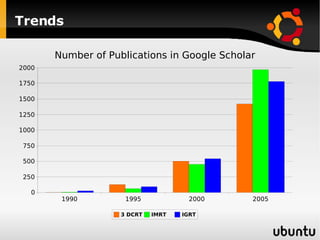
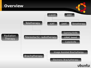
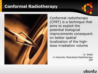
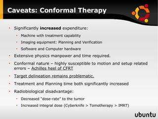
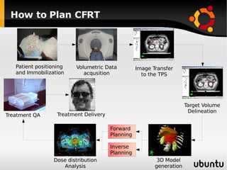
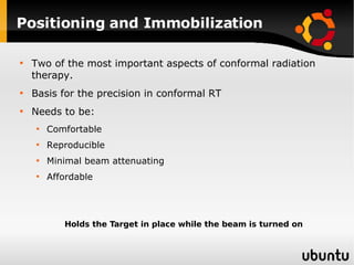
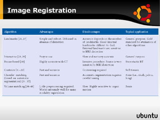
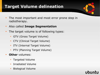
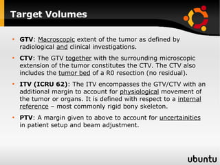
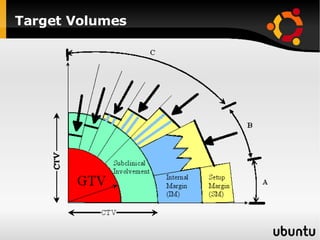
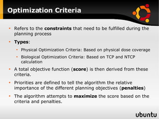
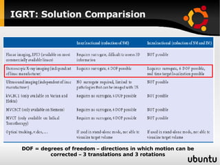
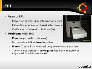
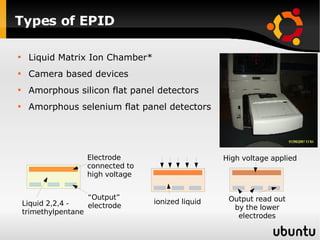
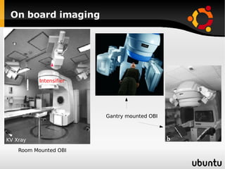

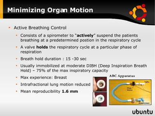
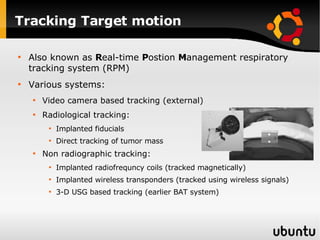
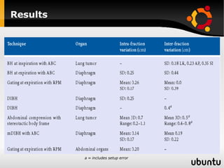
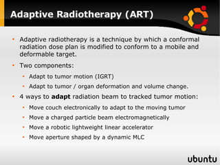


The document discusses advancements in radiation therapy, detailing various methods such as conformal radiotherapy, intensity-modulated radiotherapy (IMRT), and image-guided radiotherapy (IGRT). It emphasizes the importance of accurate target volume delineation and the challenges posed by organ motion during treatment. Additionally, the document covers the development and implementation of advanced treatment planning systems and techniques to optimize radiation dose distribution while minimizing exposure to surrounding healthy tissues.


![Arc therapy [autosaved] [autosaved]](https://cdn.slidesharecdn.com/ss_thumbnails/arctherapyautosavedautosaved-150423125828-conversion-gate01-thumbnail.jpg?width=640&height=640&fit=bounds)


![Rrecent advances in linear accelerators [MR linac]](https://cdn.slidesharecdn.com/ss_thumbnails/icroproadvance2021-recentadvancesinlinearaccelerators-211201040416-thumbnail.jpg?width=640&height=640&fit=bounds)