Downloaded 306 times


![IMAT to VMAT
New Developments
Delivery Control Systems
Elekta and Varian have introduced new linac control systems that will
systems that will be able to change the MLC leaf positions and dose
rate while the gantry is rotating.
Elekta - PreciseBeam Infinity® [can be delivered using single or
multiple arcs]
• Varian -RapidArc® [RapidArc always uses single arc to deliver
treatment]
• Philips Medical Systems, Inc - SmartArc
Both are using the term Volumetric Modulated Arc Therapy](https://image.slidesharecdn.com/arctherapyautosavedautosaved-150423125828-conversion-gate01/75/Arc-therapy-autosaved-autosaved-35-2048.jpg)


![Arc therapy [autosaved] [autosaved]](https://image.slidesharecdn.com/arctherapyautosavedautosaved-150423125828-conversion-gate01/75/Arc-therapy-autosaved-autosaved-66-2048.jpg)

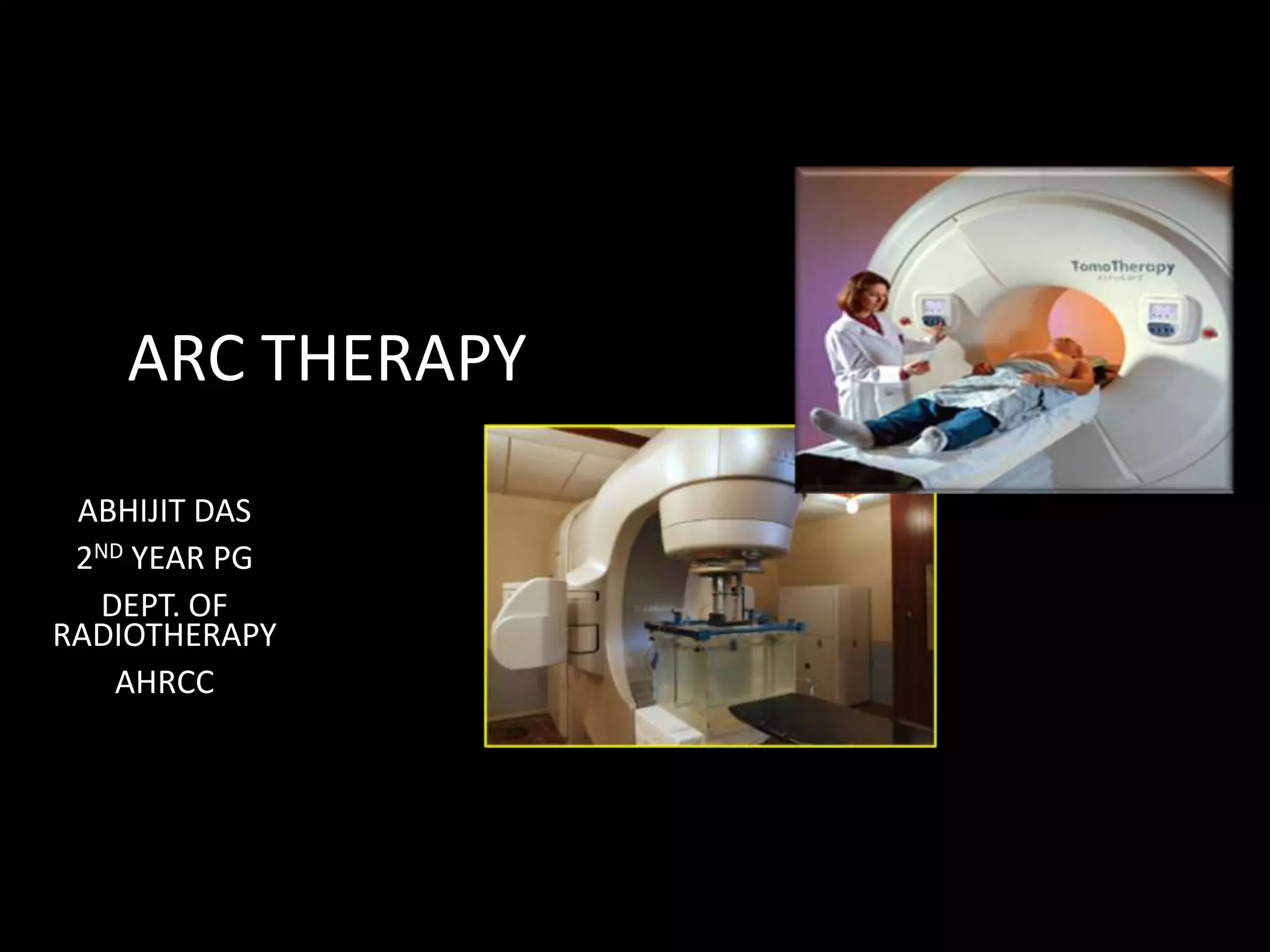
This document discusses various techniques for arc therapy including tomotherapy, intensity modulated arc therapy (IMAT), and volumetric modulated arc therapy (VMAT). It provides details on: - The history and basic concept of arc therapy which involves continuous radiation delivery from a rotating source. - Techniques like tomotherapy which uses fan beams and helical delivery, and IMAT/VMAT which modulates dose rate and leaf speed during single or multiple full gantry rotations. - The planning process for these techniques including inverse planning with direct aperture optimization to determine optimal leaf positions and weights to achieve conformal dose distributions while satisfying delivery constraints.


