Download as PDF, PPTX


![ExacTrac X-Ray 6-D Stereotactic IGRT System
• It uses a combination of optical positioning and KV radiographic imaging
for online positioning corrections.
• There are two main subsystems: an infrared-based system for initial
patient setup and precise control of couch movement using a robotic
couch and a radiographic KV X-ray imaging system for position
verification and readjustment based on internal anatomy or implanted
markers.
• Infrared system may also be used for respiratory monitoring and
signaling to LINAC for beam tracking and gating.
• Novalis Tx combines this system with an additional on-board imaging
system (MV, KV Xrays, and KVCBCT) on a multi-photon/electron beam
LINAC.
• Z. Chang, Z. Wang, Q. J. Wu et al., “Dosimetric characteristics of Novalis Tx
system with high definition multileaf collimator,” Medical Physics, vol. 35, no.
10, pp. 4460–4463, 2008.
• [38] J.-Y. Jin, F.-F. Yin, S. E. Tenn, P. M. Medin, and T. D. Solberg, “Use of the
BrainLAB ExacTrac X-Ray 6D System in Image- Guided Radiotherapy,”
Medical Dosimetry, vol. 33, no. 2, pp. 124–134, 2008.](https://image.slidesharecdn.com/igrtvikashfinal-190808034024/85/Image-Guided-Radiation-Therapy-IGRT-32-320.jpg)


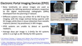
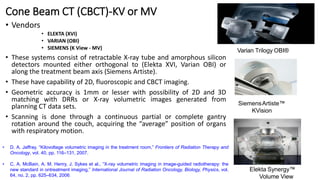
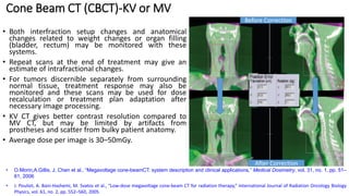
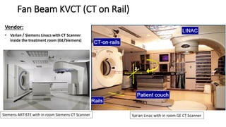
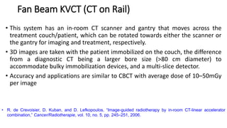
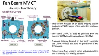
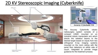
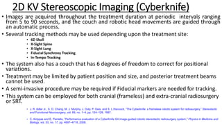
This document discusses Image Guided Radiation Therapy (IGRT). It begins by explaining that radiotherapy has traditionally used imaging for treatment planning and execution when the target is not on the surface. It then describes various IGRT technologies, dividing them into non-radiation based systems like ultrasound, cameras, electromagnetic tracking and MRI; and radiation based systems like EPID, CBCT, fan beam KVCT and MVCT. These systems provide improved target localization and allow for corrections. IGRT aims to reduce errors and improve precision of radiotherapy.


![ONFH[AVN HIP] -TRIPLE REGIME -A NOVAL SURGICAL CONCEPT .pptx](https://cdn.slidesharecdn.com/ss_thumbnails/onfhavnhip2026koaconcalicutdrgokuldevdrmashraf-260210064517-213ec005-thumbnail.jpg?width=640&height=640&fit=bounds)
