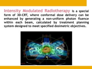
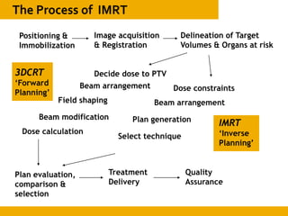
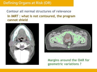
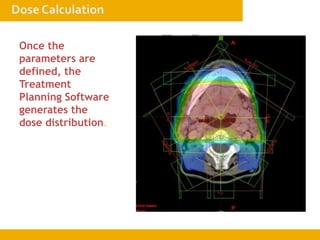
Presenter:- Dr. Musaib Mushtaq
Moderator:- Prof. Dr. Malik Mohib-ul-Haq
 IMRT is the product of advances in RT technology.
 Aims to deliver radiation more precisely to the tumour while
relatively limiting dose to the surrounding normal tissues.
 The purpose of the presentation is to discuss IMRT, its
applications and comparison with other RT method.
 Conventional radiotherapy treatment are delivered with
radiation beams that are of uniform intensity across the field .
 Wedge or compensators are used to modify the intensity
profile to offsets contour in irregularities and produce more
uniform composite dose distributions such as in techniques
using wedges.
 This process of changing beams intensity profile to meet the
goal of a composites plan is called intensity modulation.
Intensity Modulated Radiotherapy is a special
form of 3D-CRT, where conformal dose delivery can be
enhanced by generating a non-uniform photon fluence
within each beam, calculated by treatment planning
system designed to meet specified dosimetric objectives.
IMRT
 Intensity Modulated
Radiotherapy is a special
form of 3D-CRT conformal dose
delivery can be enhanced by
generating a non-uniform
photon fluence within each
beam, calculated by an inverse
treatment planning process
designed to meet specified
dosimetric objectives.
3DCRT
 3 Dimensional Conformal
Radiotherapy is the use of 3
dimensional anatomical
information to plan and deliver
treatment so that the resultant
dose distribution conforms as
closely as possible to the target
volume in 3 dimensions with
minimum dose to the
surrounding normal tissue.
 Better normal tissue sparing
 Complex target shapes
 Less toxicity
 Possibly higher dose to target
 More dose in a fraction
 A treatment planning computer system that can calculate non
uniform fluence maps for multiple beams directed from different
directions to minimizing dose to the critical normal structures.
 A system of delivering the no uniform fluence as planned.
 To deliver high dose to
tumour.
 While normal tissue should
receive minimal dose as
much as possible.
 The further NTCP curve is
to the right of TCP curve,
larger is the therapeutic
ratio.
Positioning &
Immobilization
Image acquisition
& Registration
Delineation of Target
Volumes & Organs at risk
Plan evaluation,
comparison &
selection
Treatment
Delivery
Quality
Assurance
Decide dose to PTV
Beam arrangement
Field shaping
Beam modification
Dose calculation
Select technique
Dose constraints
Beam arrangement
Plan generation
3DCRT
‘Forward
Planning’
IMRT
‘Inverse
Planning’
Vital component of conformal treatment.
• Thermoplastic sheets
• Polyurethane foam
• Vacuum forming mold
Must be attached
reproducibly on
patients !
Multislice CT Scanner
With a flat couch-top
Laser localization system
Precisely controllable
couch movements.
Simulation software
allows segmentation, contouring and
generates DRRs, 3D volumes and
isoceneters
Components
Virtual
simulation
Immobilise
in treatment
position
Align
Use contrast
Scan
Transfer
images to
graphics
workstation
Physicians
outline
target
organs-
isocenter
localized
Isocenter
marked on
patient
with laser
alignment
system
1
2
3
4
5
 CT Scan is most commonly used procedure, even other
modalities after special advantages in imaging certain types
of tumours and locations.
The CT image
CT numbers are used to
calculated electron
density
Other Imaging
modalities
MRI
PET
SPECT
MRS
The reference cut is defined
Individual CT slices are used
to create a 3 dimensional
image which can be viewed in
coronal and sagittal planes.
 It is a process of correlation different image data to identify
corresponding structures or region.
 Image fusion is the seamless mixing up of two image sets of
the same patient, it may be two different image modalities.
 Same modality in which image sets are taken at different
point of time.
Co-Registration
Surface based / Image based / Point
based.
Fused Images
Allows superior
outlining of targets in
selected areas.
1
1
Siemens medical
Solutions that help
Non-Small Cell Carcinoma
Soft Tissue Window Lung Window
Courtesy of Universitaets-Klinikum Essen
Soft tissue window Lung window FDG - PET
Green outline: CT only Red outline: CT& FDG
PET provides functional
information to an
anatomical scan
Combined PET-CT Scanners
reduce setup discrepancies
Information from PET can can help modify PTV volumes
 It refers to slice by slice delineation of anatomic regions of
interest.
 The segmented regions can be rendered in different colours
and can be viewed in beams eye view configuration or in
other planes using digital reconstruction radiographs
Usually the body and the
bones are contoured
first specialized images
segmentation features -
automatic process
Digitally Reconstructed
Radiographs (DRRs) –
place fields according to bony
landmarks
Verify with portal imaging
Fast DRRs – virtual fluoroscopy
Digital Composite
Radiographs (DCRs) –
View different ranges of CT
numbers – soft tissue, skin
marks
GTV – the gross palpable/ visible/
demonstrable extent and
localization of tumor
CTV – the volume containing GTV
and/ or subclinical microscopic
malignant disease
PTV – geometrical concept that takes
into account the net effect of all
possible geometrical variations, in
order to ensure that the prescribed
dose is actually absorbed in the CTV.
= ITV + setup margin (for setup
variations)
ITV – the CTV + the
internal margin (for normal
body movements)
Contour all normal structures of relevance
In IMRT : what is not contoured, the program
cannot shield
Margins around the OAR for
geometric variations ?
1. How many beams? – IMRT usually require more
than 4 beams
2. Coplanar or Non-
coplanar?
Use the Room’s Eye View (REV) to
get a practical idea about the
geometry of beam placement.
Even in IMRT, you
have to decide the
beam arrangement.
Mainly coplanar
beams are used,
although non-
coplanar beams
are possible
- automatic margins around PTV
(different margins in each co-
ordinate axis?)
MLCs are used to shape the field
around the PTV
- Use the Beam’s Eye View (BEV)
to place MLCs – take into account
structures to be shielded
Once the
parameters are
defined, the
Treatment
Planning Software
generates the
dose distribution.
Dose constraints have to be set to both target volumes and organs
at risk. Appropriate priorities must be set for each volume.
Practical issues :
Don’t set impossible constraints. Set appropriate priorities.
First start with constraints to a few structures – then improve the
plan by adding more constraints.
In the Plan Evaluation mode of a treatment planning
system, look at the doses received by each structure
of interest.
Evaluate the dose distribution characteristics of one
or more plans using dose volume histograms (DVH)
The cumulative (integral)
DVH represents a
cumulative frequency
distribution of the dose
integrated over the VOI.
In the differential DVH,
the ordinate represents
the absolute or relative
volume which receives the
dose specified on the
abscissa within a specified
range of dose.
Rectum
Bladder
PTV
PTV
Always verify the anatomical dose distribution slice by
slice, in order to identify where underdosage or
overdosage is occurring.
Overdosage : 117%
Underdosage: <90%
 An optimal plan should deliver tumouricidal dose to the entire tumour
and spare all the normal tissue.
 To achieve quantitative biological endpoint ,model have been
developed involving biological indices such asTCP and normal tissue
complication probability.
 Dose distributions of competing plan are evaluated by viewing isodose
curves in individual slices, orthogonal planes or 3D isodose surface.
3DCRT IMRT
• Change beam arrangement
• Change beam weightage
• Adjust field margins
• Add modifiers
• Change beam arrangement
• Change dose constraints
• Contour new areas/
dummy areas.
 Based on inverse planning
 initially , a ct scan is performed on the affected region.
 radiation oncologist defines the ptv.
 enters the plan criteria ; max dose ,mini dose, desired
limiting dose and a dose volume histogram.
 Then ,an optimisation program is run to find the treatment
plan which best matches all the input criteria.
IMRT Delivery Tomotherapy
MLC based IMRT
Compensator based
IMRT
1. The fluence
map is
generated
2. A special software converts it
into a compensator file
3. A computerized milling
machine creates a Styrofoam
mold
4. The mold is filled with the
compensator material (eg. Tin
granules, brass cubes, cerrobend) and
the compensator box can be attached
to the wedge slot.
Rotating Slit Beam
Temporally modulated
slit MLC with 1 or 2
banks. Nomos MIMiC
Attached to a linac or dedicated systems
Serial tomotherapy
Helical tomotherapy
1. Static Mode (Step & Shoot)
=
Mainly delivered in 2 ways: static & dynamic MLCs
The intensity pattern is decomposed into a number of static
segments, each of uniform intensity
The number of intensity levels determine the complexity or
the smoothness of the delivered fluence.
2. Dynamic mode (Sliding window)
3. Intensity Modulated Arc Therapy (IMAT)
4. Volumetric Modulated Arc Therapy (VMAT)
The beam stays ON, and the MLC
leaves move continuously at
variable speeds
dose rate is also modulated to
achieve efficient delivery
When viewed from BEV, a
narrow slit slides across the
beam from one edge to other –
sliding window
Static Mode
(Step & Shoot)
Dynamic mode
(Sliding window)
• Conceptually simpler
• No need to control individual
leaf speeds
• interrupted treatments are
easier to resume
• Easier to verify intensity
patterns in each subfield
• Fewer MUs
• Regions with zero dose are
more easily delivered
• Smoothly varying intensities
• Only one field per beam
direction
• Less time consuming
1. Check beam
data transfer
2. Position &
Immobilize
3. Match/Change
isocenter with lasers
4. Visually verify
MLC positions
5. Take Portal
images
6. Match with DRRs
in EPID software
 MORE COMPLEXITY
 NEED FOR NEW EQUIPMENTS
 MORE NEED FOR QA
 LONGERTREARMENTTIMES
 HIGHER RISK OF GEOGRAPHICAL MISS
THANKS

IMRT by Musaib Mushtaq.ppt

  • 1.
    Presenter:- Dr. MusaibMushtaq Moderator:- Prof. Dr. Malik Mohib-ul-Haq
  • 2.
     IMRT isthe product of advances in RT technology.  Aims to deliver radiation more precisely to the tumour while relatively limiting dose to the surrounding normal tissues.  The purpose of the presentation is to discuss IMRT, its applications and comparison with other RT method.
  • 3.
     Conventional radiotherapytreatment are delivered with radiation beams that are of uniform intensity across the field .  Wedge or compensators are used to modify the intensity profile to offsets contour in irregularities and produce more uniform composite dose distributions such as in techniques using wedges.  This process of changing beams intensity profile to meet the goal of a composites plan is called intensity modulation.
  • 4.
    Intensity Modulated Radiotherapyis a special form of 3D-CRT, where conformal dose delivery can be enhanced by generating a non-uniform photon fluence within each beam, calculated by treatment planning system designed to meet specified dosimetric objectives.
  • 5.
    IMRT  Intensity Modulated Radiotherapyis a special form of 3D-CRT conformal dose delivery can be enhanced by generating a non-uniform photon fluence within each beam, calculated by an inverse treatment planning process designed to meet specified dosimetric objectives. 3DCRT  3 Dimensional Conformal Radiotherapy is the use of 3 dimensional anatomical information to plan and deliver treatment so that the resultant dose distribution conforms as closely as possible to the target volume in 3 dimensions with minimum dose to the surrounding normal tissue.
  • 6.
     Better normaltissue sparing  Complex target shapes  Less toxicity  Possibly higher dose to target  More dose in a fraction
  • 7.
     A treatmentplanning computer system that can calculate non uniform fluence maps for multiple beams directed from different directions to minimizing dose to the critical normal structures.  A system of delivering the no uniform fluence as planned.
  • 8.
     To deliverhigh dose to tumour.  While normal tissue should receive minimal dose as much as possible.  The further NTCP curve is to the right of TCP curve, larger is the therapeutic ratio.
  • 9.
    Positioning & Immobilization Image acquisition &Registration Delineation of Target Volumes & Organs at risk Plan evaluation, comparison & selection Treatment Delivery Quality Assurance Decide dose to PTV Beam arrangement Field shaping Beam modification Dose calculation Select technique Dose constraints Beam arrangement Plan generation 3DCRT ‘Forward Planning’ IMRT ‘Inverse Planning’
  • 10.
    Vital component ofconformal treatment. • Thermoplastic sheets • Polyurethane foam • Vacuum forming mold Must be attached reproducibly on patients !
  • 12.
    Multislice CT Scanner Witha flat couch-top Laser localization system Precisely controllable couch movements. Simulation software allows segmentation, contouring and generates DRRs, 3D volumes and isoceneters Components
  • 13.
    Virtual simulation Immobilise in treatment position Align Use contrast Scan Transfer imagesto graphics workstation Physicians outline target organs- isocenter localized Isocenter marked on patient with laser alignment system 1 2 3 4 5
  • 14.
     CT Scanis most commonly used procedure, even other modalities after special advantages in imaging certain types of tumours and locations.
  • 15.
    The CT image CTnumbers are used to calculated electron density Other Imaging modalities MRI PET SPECT MRS
  • 16.
    The reference cutis defined Individual CT slices are used to create a 3 dimensional image which can be viewed in coronal and sagittal planes.
  • 17.
     It isa process of correlation different image data to identify corresponding structures or region.  Image fusion is the seamless mixing up of two image sets of the same patient, it may be two different image modalities.  Same modality in which image sets are taken at different point of time.
  • 18.
    Co-Registration Surface based /Image based / Point based. Fused Images Allows superior outlining of targets in selected areas.
  • 19.
    1 1 Siemens medical Solutions thathelp Non-Small Cell Carcinoma Soft Tissue Window Lung Window Courtesy of Universitaets-Klinikum Essen Soft tissue window Lung window FDG - PET Green outline: CT only Red outline: CT& FDG PET provides functional information to an anatomical scan Combined PET-CT Scanners reduce setup discrepancies Information from PET can can help modify PTV volumes
  • 20.
     It refersto slice by slice delineation of anatomic regions of interest.  The segmented regions can be rendered in different colours and can be viewed in beams eye view configuration or in other planes using digital reconstruction radiographs
  • 21.
    Usually the bodyand the bones are contoured first specialized images segmentation features - automatic process Digitally Reconstructed Radiographs (DRRs) – place fields according to bony landmarks Verify with portal imaging Fast DRRs – virtual fluoroscopy Digital Composite Radiographs (DCRs) – View different ranges of CT numbers – soft tissue, skin marks
  • 22.
    GTV – thegross palpable/ visible/ demonstrable extent and localization of tumor CTV – the volume containing GTV and/ or subclinical microscopic malignant disease PTV – geometrical concept that takes into account the net effect of all possible geometrical variations, in order to ensure that the prescribed dose is actually absorbed in the CTV. = ITV + setup margin (for setup variations) ITV – the CTV + the internal margin (for normal body movements)
  • 23.
    Contour all normalstructures of relevance In IMRT : what is not contoured, the program cannot shield Margins around the OAR for geometric variations ?
  • 24.
    1. How manybeams? – IMRT usually require more than 4 beams 2. Coplanar or Non- coplanar? Use the Room’s Eye View (REV) to get a practical idea about the geometry of beam placement.
  • 25.
    Even in IMRT,you have to decide the beam arrangement. Mainly coplanar beams are used, although non- coplanar beams are possible
  • 26.
    - automatic marginsaround PTV (different margins in each co- ordinate axis?) MLCs are used to shape the field around the PTV - Use the Beam’s Eye View (BEV) to place MLCs – take into account structures to be shielded
  • 27.
    Once the parameters are defined,the Treatment Planning Software generates the dose distribution.
  • 28.
    Dose constraints haveto be set to both target volumes and organs at risk. Appropriate priorities must be set for each volume. Practical issues : Don’t set impossible constraints. Set appropriate priorities. First start with constraints to a few structures – then improve the plan by adding more constraints.
  • 30.
    In the PlanEvaluation mode of a treatment planning system, look at the doses received by each structure of interest.
  • 31.
    Evaluate the dosedistribution characteristics of one or more plans using dose volume histograms (DVH) The cumulative (integral) DVH represents a cumulative frequency distribution of the dose integrated over the VOI. In the differential DVH, the ordinate represents the absolute or relative volume which receives the dose specified on the abscissa within a specified range of dose. Rectum Bladder PTV PTV
  • 32.
    Always verify theanatomical dose distribution slice by slice, in order to identify where underdosage or overdosage is occurring. Overdosage : 117% Underdosage: <90%
  • 33.
     An optimalplan should deliver tumouricidal dose to the entire tumour and spare all the normal tissue.  To achieve quantitative biological endpoint ,model have been developed involving biological indices such asTCP and normal tissue complication probability.  Dose distributions of competing plan are evaluated by viewing isodose curves in individual slices, orthogonal planes or 3D isodose surface.
  • 34.
    3DCRT IMRT • Changebeam arrangement • Change beam weightage • Adjust field margins • Add modifiers • Change beam arrangement • Change dose constraints • Contour new areas/ dummy areas.
  • 35.
     Based oninverse planning  initially , a ct scan is performed on the affected region.  radiation oncologist defines the ptv.  enters the plan criteria ; max dose ,mini dose, desired limiting dose and a dose volume histogram.  Then ,an optimisation program is run to find the treatment plan which best matches all the input criteria.
  • 36.
    IMRT Delivery Tomotherapy MLCbased IMRT Compensator based IMRT
  • 37.
    1. The fluence mapis generated 2. A special software converts it into a compensator file 3. A computerized milling machine creates a Styrofoam mold 4. The mold is filled with the compensator material (eg. Tin granules, brass cubes, cerrobend) and the compensator box can be attached to the wedge slot.
  • 38.
    Rotating Slit Beam Temporallymodulated slit MLC with 1 or 2 banks. Nomos MIMiC Attached to a linac or dedicated systems Serial tomotherapy Helical tomotherapy
  • 39.
    1. Static Mode(Step & Shoot) = Mainly delivered in 2 ways: static & dynamic MLCs The intensity pattern is decomposed into a number of static segments, each of uniform intensity The number of intensity levels determine the complexity or the smoothness of the delivered fluence.
  • 40.
    2. Dynamic mode(Sliding window) 3. Intensity Modulated Arc Therapy (IMAT) 4. Volumetric Modulated Arc Therapy (VMAT) The beam stays ON, and the MLC leaves move continuously at variable speeds dose rate is also modulated to achieve efficient delivery When viewed from BEV, a narrow slit slides across the beam from one edge to other – sliding window
  • 41.
    Static Mode (Step &Shoot) Dynamic mode (Sliding window) • Conceptually simpler • No need to control individual leaf speeds • interrupted treatments are easier to resume • Easier to verify intensity patterns in each subfield • Fewer MUs • Regions with zero dose are more easily delivered • Smoothly varying intensities • Only one field per beam direction • Less time consuming
  • 42.
    1. Check beam datatransfer 2. Position & Immobilize 3. Match/Change isocenter with lasers 4. Visually verify MLC positions 5. Take Portal images 6. Match with DRRs in EPID software
  • 43.
     MORE COMPLEXITY NEED FOR NEW EQUIPMENTS  MORE NEED FOR QA  LONGERTREARMENTTIMES  HIGHER RISK OF GEOGRAPHICAL MISS
  • 44.