Downloaded 723 times

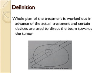
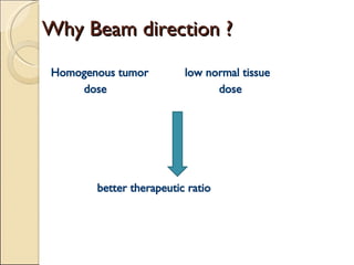
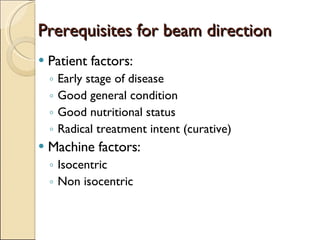
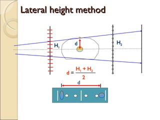
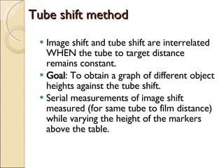
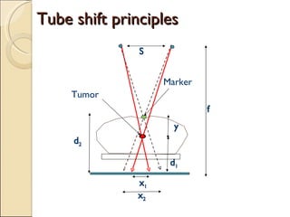
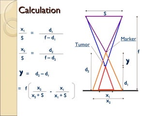
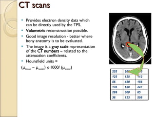


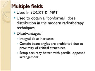

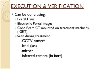

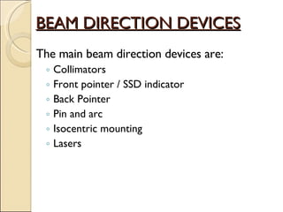
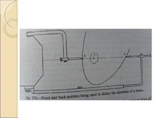


Beam direction techniques are used to accurately direct radiation beams towards the tumor while sparing surrounding healthy tissues. Key steps include patient localization using imaging like CT/MRI to delineate the tumor and organs, patient positioning and immobilization, field selection using beam directing devices like lasers, collimators and pointers, and dose distribution analysis to calculate and verify the prescribed dose. Proper beam direction allows obtaining conformal dose distributions and reproducible treatments for better therapeutic outcomes.


![Arc therapy [autosaved] [autosaved]](https://cdn.slidesharecdn.com/ss_thumbnails/arctherapyautosavedautosaved-150423125828-conversion-gate01-thumbnail.jpg?width=640&height=640&fit=bounds)


![Management Of Early Stage Ca Cervix [Autosaved]](https://cdn.slidesharecdn.com/ss_thumbnails/management-of-early-stage-ca-cervix-autosaved-1233338415127954-2-thumbnail.jpg?width=640&height=640&fit=bounds)


