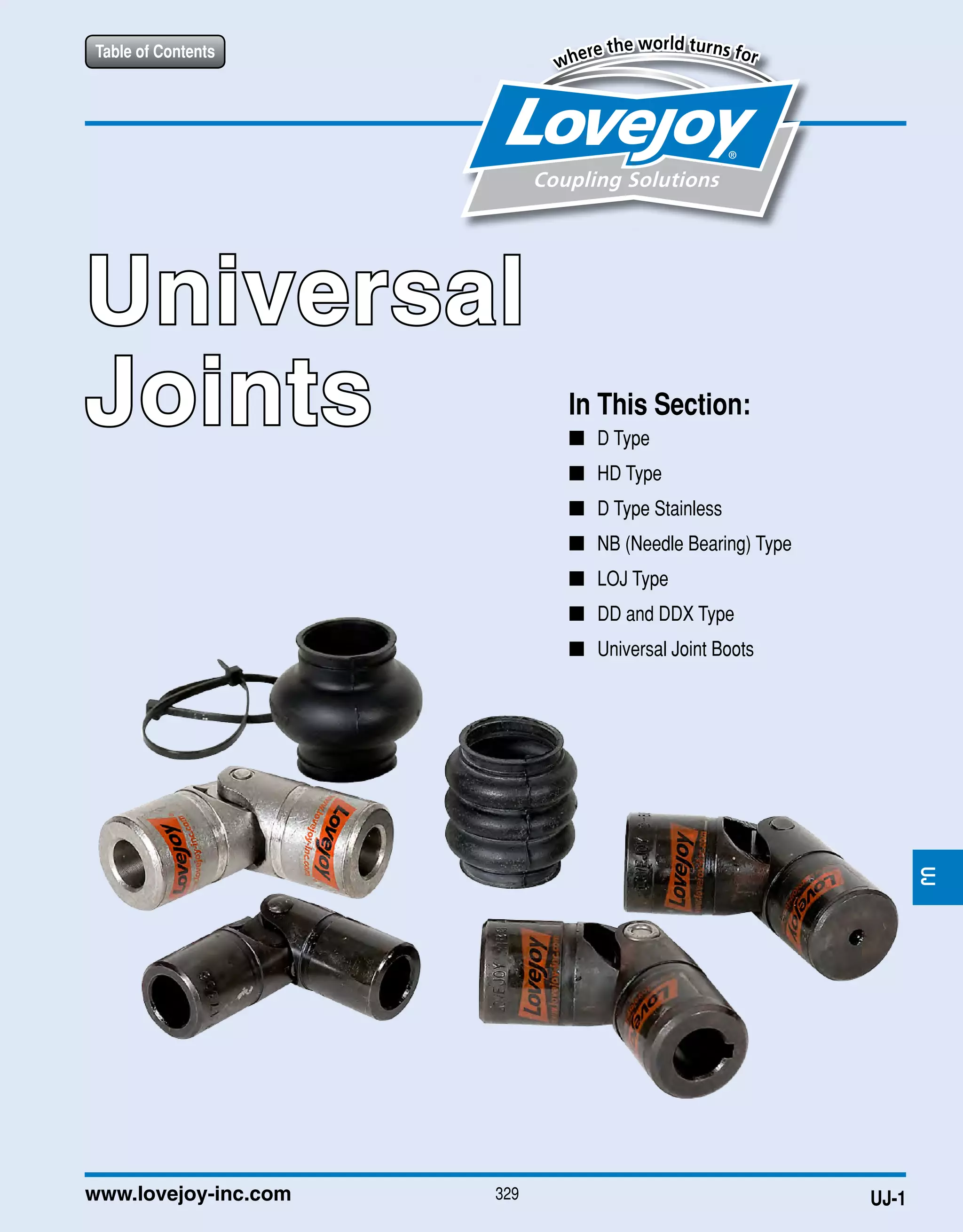
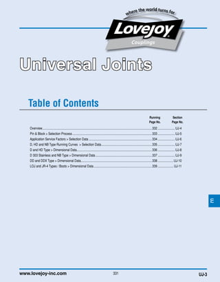
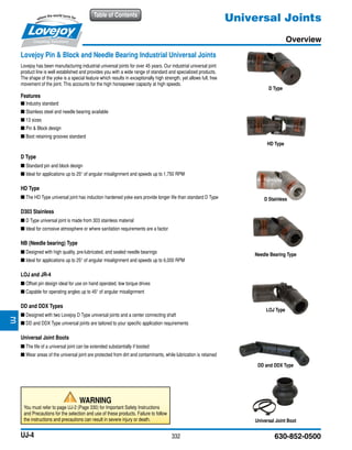
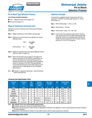
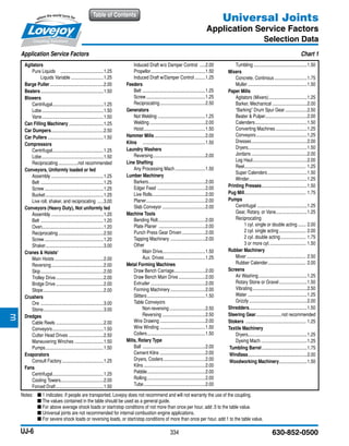
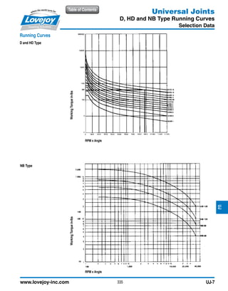
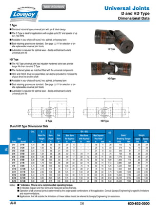
The document provides information on Lovejoy universal joints, including:
- An overview of Lovejoy's pin & block and needle bearing universal joints, describing the various types available.
- A selection process outlining how to determine the proper universal joint size for an application based on torque, RPM, working angle, and service factor.
- Charts for application service factors and universal joint running curves to aid in the selection process.
- Dimensional data and specifications for the different universal joint types.
JWJISCJSFMCGHPGDDTSPUJVSDRSLDED
335
DESIGN ANALYSIS OF UNIVERSAL JOINT SHAFT FOR ROLLING MILLSSughosh Deshmukh
The properties of steels made by rolling of billets
are mainly dependent on the process of forming. The
performance of the rolling mill depends on the Universal
joint shaft through which the power is transmitted to the
rollers of a mill. This report mainly focuses on the
analysis of universal joint shaft for rolling mills because this
shaft is subjected to vibrations caused due to the jerk
produced during the passing of billet through the rollers.
Design mini-project for TY mechanical studentsRavindra Shinde
In these project, we have designed a lifting table suitable to use in college . By adjusting the height of table any student can have proper sitting posture and position. It is also helpful for programmers/coders who have to seat for a long time, by having such a table they can do coding in a standing position too.
Design, Analysis and Manufacturing of Braking system for an Universal Terrain...EditorIJAERD
The paper represents the designing, analyzing and fabrication of braking system as well as suspension
system for a Universal terrain vehicle that too being inside the constraints in the Rulebook provided by Rally Car Design
Challenge.
The main idea behind braking system is to design, analyze as well as to simulate the Hydraulic disc type of brakes
installed on a Universal Terrain Vehicle. An UTV as the name suggests is designed to handle a vast variety of terrain
than that of other conventional vehicles. The Braking system which is the most important constraint for handling has
undergone a substantial amount of development in the past. Thus, the topic is focused on designing a form of mentioned
braking system incorporating dynamics of the vehicle with providing optimum performance of the vehicle while
minimizing driver’s efforts.
Parameters like Dynamic weight transfer, Static weight distribution ratio, Pedal force, and etcetera were evaluated to
attain the desired performance. As an UTV has to be stopped or slowed down more often in rough terrains, ability of the
vehicle to stop efficiently and in adequate time becomes imperative. The calipers were selected by using required
calculations and chosen from the systems available in market, the calculations were then validated using CATIA. The
design of Brake Discs were decided using the required calculations and also the caliper mountings on SOLIDWORKS
and will be manufactured later. The component designs are analyzed in ANSYS and checked whether they are compatible
for our vehicle.
DESIGN AND ANALYSIS OF ELECTRO HYDRAULIC THRUSTER BRAKE FOR LIFTING MACHINEijiert bestjournal
Brakes are very important part of most important pa rt of the crane. Failure of brakes is often associated with the sudden and massive failure. In the recent era disc brakes for a crane has become very important. And incorporating disc often asks greater efficiency and exact position stop when we apply disc brake. The power of disc br ake is very higher than of conventional drum brakes. If the liner wear and tear is less and if auto adjustment is provided to disc brakes,it gives an advantage of less maintenance as well grea ter safety to machine and operator.
Jtc5 worm gear screw lifter,small mechanical worm gear screw jacks, stainless steel worm gear screw jack,small worm geared screw jack,small industrial worm screw jacks,lifting worm gear jack, jack worm screw static load capacity 5 kn, high speed torque 2.6 n.m, low speed torque 0.8 n.m. lead screw (spindle) Tr18x4. high speed gear ratio 1/4, low speed gear ratio 1/16. upright or inverted translating screw, rotating screw and keyed screw configurations. precision positioning, self locking lead screw which support the loads and hold position without brake mechamism. hand wheel or hand crank manual operation, or single phase or three phases electric motor driven, gear motor driven or dc 24v gear reduction motor drives. thread end, clevis end, plain end, forked head and top plate (flange type) for lead screw (spindle) end types. customized various length stroke, under tension load, maximum 400 mm stroke. single screw jack or multiple screw jacks system arrangements.
ball screw jack,electric ball screw jack,manual ball screw jack,ball screw actuators,ball screw drive,ball screw lifts features:
1. Lifting force 5kN to 500kN. Under max. lifting force, input shaft required torque, high ratio 1.3Nm to 318Nm, low ratio 0.62Nm to 178Nm.
2. Ball screw diameter 16 mm to 100 mm, lead 5 mm to 24 mm.
3. Worm gear ratio 1/5 to 1/32.
4. Translating screw, rotating screw, keyed screw configurations in upright or inverted mounting orientation.
5. High speed, high precision, high efficiency, high duty cycle, high performance, high frequency operation, low drive torque, long service life.
6. motorized ball screw jack by 3-phase or single phase electric motor/gearmotor, manual ball screw jack by hand wheel/hand crank.
7. Ball screw ends include top plate, clevis end, plain end and threaded end.
8. Individually or multiple ball screw jack lifting system arrangements are available.
9. Application in steel, pipe, tube, plate, roll forming roller adjustment, feeder straightener rolls adjustment, adjusting synchronous coil feed lines rolls, precision roller leveler, coil sheet slitter line, paint coating line, cut to length line, tension levelling line, continuous galvanizing line, beverage production line, foam concrete cutting machine, sanding machine, heavy vehicles mobile lifting platform, bottle monitoring system height adjustment, conveyor adjustment, plate saw angle adjustment, spray infeed conveyor lift system, theatre stage lifting platform, solar tracker, satellite dish antenna azimuth, raising sluice gate, screw scissor lift table, synchronized lifting system, food processing lifting system, extrusion machine, cnc steel leveling machine, blow molding machine, curing oven lifts, bolted tank, steel shuttering concrete beams adjustment, vintage industrial crank desk, solar panel tracking system, railway maintenance lifting jack, damper adjustment, continuous casting, cnc cut to length machine, robotics arm raising, palletizer, extrusion machine, motorized self-raising tower system, angle tilt adjustments with double clevis, aircraft docking system, open and close flood gates, metallurgy industry, mining industry, chemical industry, construction industry and irrigation industry.
Note: ball screw without self-locking, braking motor, brake mechanism or other locking systems are required when keep the position. When a motorized ball screw jack, less power is required than an equivalent size machine screw jack.
An automotive jack is a device used to raise all or part of a vehicle into the air in order to facilitate repairs. Most people are familiar with the basic car jack (manually operated) that is still included as standard equipment with most new cars. These days, a car jack is an important tool to have in our vehicle due to unknown upcoming event such as flat tire in our journey. Even so, people who like to rotate their tires themselves or who may install snow tires before the winter and remove them in the spring need to use a jack to perform the job. Changing a flat tire is not a very pleasant experience. Women have a much lighter skeleton that means, among other things, woman can’t pull more forces as well as men and are at greater risk of skeletal injuries. Usually the car purposely tries to get a flat tire at the least opportune moments.
An Experimental and Theoretical Analysis & Modification of a Shock Absorber o...IJSRD
A suspension system or shock absorber is a mechanical device designed to smooth out or damp shock impulse, and dissipate kinetic energy. The shock absorbers duty is to absorb or dissipate energy and the helical spring is the most common element that has been used in suspension system. In this present study Non alloy steel helical spring will be used to suspend vehicle system. The uniform loading effect has been studied and Experimental, FEA analysis will be compared with analytical solution. Afterwards, the analysis will be done by considering different parameters. Experimental analysis will be done to validate the strength and modal analysis is done to determine the displacements for different loading condi-tion. Comparison is done by changing the wire diameter of the coil spring to check the best dimension for the spring in shock absorber. Modeling and Analysis is done by using Pro/ENGINEER and ANSYS respe240
GEOMETRIC OPTIMIZATION AND MANUFACTURING PROCESS OF SIX CYLINDER DIESEL ENGIN...Ijripublishers Ijri
The crankshaft is that part of an engine which translates reciprocating linear piston motion into rotation. To convert the
reciprocating motion into rotation, the crankshaft has "crank" or "crankpins", additional bearing surfaces whose axis is
offset from that of the crank, to which the "big ends" of the connecting rods from each cylinder attach.
The aim of the project work is to optimize the geometry shape of 6-cylinder diesel engine crank shaft to reduce the failures
and to reduce the weight. And also this project work will provide the brief explanation of manufacturing process.
Initially literature survey and data collection will be done to understand methodology.
Design calculations will be done to get parameters of object for drafting.
3D model will be prepared according to the obtained parameters.
Analysis will be conducted on crank shaft to rectify failures by optimizing geometric shape. Also best material will be
suggested by analyzing and comparing results with the variation of materials.
Mold tool design will be done and assembly will be prepared according to that.
Cnc program will be prepared for die set using cam
Toyota 42-6FGU25 Forklift Service Repair Manualjkksemd yeuyhd
This is the Highly Detailed factory service repair manual for theTOYOTA 42-6FGU25 FORKLIFT , this Service Manual has detailed illustrations as well as step by step instructions,It is 100 percents complete and intact. they are specifically written for the do-it-yourself-er as well as the experienced mechanic.TOYOTA 42-6FGU25 FORKLIFT Service Repair Workshop Manual provides step-by-step instructions based on the complete dis-assembly of the machine. It is this level of detail, along with hundreds of photos and illustrations, that guide the reader through each service and repair procedure. Complete download comes in pdf format which can work under all PC based windows operating system and Mac also, All pages are printable. Using this repair manual is an inexpensive way to keep your vehicle working properly.
Service Repair Manual Covers:
Foreword
Section Index
General
Engine
Torque Converter
Propeller Shaft
Differential
Front Axle
Rear Axle
Steering
Brake
Body
Material Handling System
Mast
Cylinder
Oil Pump
Oil Control Valve
Appendix
Wire Diagrams
File Format: PDF
Compatible: All Versions of Windows & Mac
Language: English
Requirements: Adobe PDF Reader
NO waiting, Buy from responsible seller and get INSTANT DOWNLOAD, Without wasting your hard-owned money on uncertainty or surprise! All pages are is great to haveTOYOTA 42-6FGU25 FORKLIFT Service Repair Workshop Manual.
Looking for some other Service Repair Manual,please check:
https://www.aservicemanualpdf.com/
Thanks for visiting!
8
Toyota 42-6FGU15 Forklift Service Repair Manualhjskejdm
This is the Highly Detailed factory service repair manual for theTOYOTA 42-6FGU15 FORKLIFT, this Service Manual has detailed illustrations as well as step by step instructions,It is 100 percents complete and intact. they are specifically written for the do-it-yourself-er as well as the experienced mechanic.TOYOTA 42-6FGU15 FORKLIFT Service Repair Workshop Manual provides step-by-step instructions based on the complete dis-assembly of the machine. It is this level of detail, along with hundreds of photos and illustrations, that guide the reader through each service and repair procedure. Complete download comes in pdf format which can work under all PC based windows operating system and Mac also, All pages are printable. Using this repair manual is an inexpensive way to keep your vehicle working properly.
Service Repair Manual Covers:
Foreword
Section Index
General
Engine
Torque Converter
Propeller Shaft
Differential
Front Axle
Rear Axle
Steering
Brake
Body
Material Handling System
Mast
Cylinder
Oil Pump
Oil Control Valve
Appendix
Wire Diagrams
File Format: PDF
Compatible: All Versions of Windows & Mac
Language: English
Requirements: Adobe PDF Reader
NO waiting, Buy from responsible seller and get INSTANT DOWNLOAD, Without wasting your hard-owned money on uncertainty or surprise! All pages are is great to haveTOYOTA 42-6FGU15 FORKLIFT Service Repair Workshop Manual.
Looking for some other Service Repair Manual,please check:
https://www.aservicemanualpdf.com/
Thanks for visiting!
8
Toyota 42-6FGU20 Forklift Service Repair Manualjkksejkdm
This is the Highly Detailed factory service repair manual for theTOYOTA 42-6FGU20 FORKLIFT, this Service Manual has detailed illustrations as well as step by step instructions,It is 100 percents complete and intact. they are specifically written for the do-it-yourself-er as well as the experienced mechanic.TOYOTA 42-6FGU20 FORKLIFT Service Repair Workshop Manual provides step-by-step instructions based on the complete dis-assembly of the machine. It is this level of detail, along with hundreds of photos and illustrations, that guide the reader through each service and repair procedure. Complete download comes in pdf format which can work under all PC based windows operating system and Mac also, All pages are printable. Using this repair manual is an inexpensive way to keep your vehicle working properly.
Service Repair Manual Covers:
Foreword
Section Index
General
Engine
Torque Converter
Propeller Shaft
Differential
Front Axle
Rear Axle
Steering
Brake
Body
Material Handling System
Mast
Cylinder
Oil Pump
Oil Control Valve
Appendix
Wire Diagrams
File Format: PDF
Compatible: All Versions of Windows & Mac
Language: English
Requirements: Adobe PDF Reader
NO waiting, Buy from responsible seller and get INSTANT DOWNLOAD, Without wasting your hard-owned money on uncertainty or surprise! All pages are is great to haveTOYOTA 42-6FGU20 FORKLIFT Service Repair Workshop Manual.
Looking for some other Service Repair Manual,please check:
https://www.aservicemanualpdf.com/
Thanks for visiting!
8
Democratizing Fuzzing at Scale by Abhishek Aryaabh.arya
Presented at NUS: Fuzzing and Software Security Summer School 2024
This keynote talks about the democratization of fuzzing at scale, highlighting the collaboration between open source communities, academia, and industry to advance the field of fuzzing. It delves into the history of fuzzing, the development of scalable fuzzing platforms, and the empowerment of community-driven research. The talk will further discuss recent advancements leveraging AI/ML and offer insights into the future evolution of the fuzzing landscape.
Hybrid optimization of pumped hydro system and solar- Engr. Abdul-Azeez.pdffxintegritypublishin
Advancements in technology unveil a myriad of electrical and electronic breakthroughs geared towards efficiently harnessing limited resources to meet human energy demands. The optimization of hybrid solar PV panels and pumped hydro energy supply systems plays a pivotal role in utilizing natural resources effectively. This initiative not only benefits humanity but also fosters environmental sustainability. The study investigated the design optimization of these hybrid systems, focusing on understanding solar radiation patterns, identifying geographical influences on solar radiation, formulating a mathematical model for system optimization, and determining the optimal configuration of PV panels and pumped hydro storage. Through a comparative analysis approach and eight weeks of data collection, the study addressed key research questions related to solar radiation patterns and optimal system design. The findings highlighted regions with heightened solar radiation levels, showcasing substantial potential for power generation and emphasizing the system's efficiency. Optimizing system design significantly boosted power generation, promoted renewable energy utilization, and enhanced energy storage capacity. The study underscored the benefits of optimizing hybrid solar PV panels and pumped hydro energy supply systems for sustainable energy usage. Optimizing the design of solar PV panels and pumped hydro energy supply systems as examined across diverse climatic conditions in a developing country, not only enhances power generation but also improves the integration of renewable energy sources and boosts energy storage capacities, particularly beneficial for less economically prosperous regions. Additionally, the study provides valuable insights for advancing energy research in economically viable areas. Recommendations included conducting site-specific assessments, utilizing advanced modeling tools, implementing regular maintenance protocols, and enhancing communication among system components.
Vaccine management system project report documentation..pdfKamal Acharya
The Division of Vaccine and Immunization is facing increasing difficulty monitoring vaccines and other commodities distribution once they have been distributed from the national stores. With the introduction of new vaccines, more challenges have been anticipated with this additions posing serious threat to the already over strained vaccine supply chain system in Kenya.
COLLEGE BUS MANAGEMENT SYSTEM PROJECT REPORT.pdfKamal Acharya
The College Bus Management system is completely developed by Visual Basic .NET Version. The application is connect with most secured database language MS SQL Server. The application is develop by using best combination of front-end and back-end languages. The application is totally design like flat user interface. This flat user interface is more attractive user interface in 2017. The application is gives more important to the system functionality. The application is to manage the student’s details, driver’s details, bus details, bus route details, bus fees details and more. The application has only one unit for admin. The admin can manage the entire application. The admin can login into the application by using username and password of the admin. The application is develop for big and small colleges. It is more user friendly for non-computer person. Even they can easily learn how to manage the application within hours. The application is more secure by the admin. The system will give an effective output for the VB.Net and SQL Server given as input to the system. The compiled java program given as input to the system, after scanning the program will generate different reports. The application generates the report for users. The admin can view and download the report of the data. The application deliver the excel format reports. Because, excel formatted reports is very easy to understand the income and expense of the college bus. This application is mainly develop for windows operating system users. In 2017, 73% of people enterprises are using windows operating system. So the application will easily install for all the windows operating system users. The application-developed size is very low. The application consumes very low space in disk. Therefore, the user can allocate very minimum local disk space for this application.
Final project report on grocery store management system..pdfKamal Acharya
In today’s fast-changing business environment, it’s extremely important to be able to respond to client needs in the most effective and timely manner. If your customers wish to see your business online and have instant access to your products or services.
Online Grocery Store is an e-commerce website, which retails various grocery products. This project allows viewing various products available enables registered users to purchase desired products instantly using Paytm, UPI payment processor (Instant Pay) and also can place order by using Cash on Delivery (Pay Later) option. This project provides an easy access to Administrators and Managers to view orders placed using Pay Later and Instant Pay options.
In order to develop an e-commerce website, a number of Technologies must be studied and understood. These include multi-tiered architecture, server and client-side scripting techniques, implementation technologies, programming language (such as PHP, HTML, CSS, JavaScript) and MySQL relational databases. This is a project with the objective to develop a basic website where a consumer is provided with a shopping cart website and also to know about the technologies used to develop such a website.
This document will discuss each of the underlying technologies to create and implement an e- commerce website.
Water scarcity is the lack of fresh water resources to meet the standard water demand. There are two type of water scarcity. One is physical. The other is economic water scarcity.
About
Indigenized remote control interface card suitable for MAFI system CCR equipment. Compatible for IDM8000 CCR. Backplane mounted serial and TCP/Ethernet communication module for CCR remote access. IDM 8000 CCR remote control on serial and TCP protocol.
• Remote control: Parallel or serial interface.
• Compatible with MAFI CCR system.
• Compatible with IDM8000 CCR.
• Compatible with Backplane mount serial communication.
• Compatible with commercial and Defence aviation CCR system.
• Remote control system for accessing CCR and allied system over serial or TCP.
• Indigenized local Support/presence in India.
• Easy in configuration using DIP switches.
Technical Specifications
Indigenized remote control interface card suitable for MAFI system CCR equipment. Compatible for IDM8000 CCR. Backplane mounted serial and TCP/Ethernet communication module for CCR remote access. IDM 8000 CCR remote control on serial and TCP protocol.
Key Features
Indigenized remote control interface card suitable for MAFI system CCR equipment. Compatible for IDM8000 CCR. Backplane mounted serial and TCP/Ethernet communication module for CCR remote access. IDM 8000 CCR remote control on serial and TCP protocol.
• Remote control: Parallel or serial interface
• Compatible with MAFI CCR system
• Copatiable with IDM8000 CCR
• Compatible with Backplane mount serial communication.
• Compatible with commercial and Defence aviation CCR system.
• Remote control system for accessing CCR and allied system over serial or TCP.
• Indigenized local Support/presence in India.
Application
• Remote control: Parallel or serial interface.
• Compatible with MAFI CCR system.
• Compatible with IDM8000 CCR.
• Compatible with Backplane mount serial communication.
• Compatible with commercial and Defence aviation CCR system.
• Remote control system for accessing CCR and allied system over serial or TCP.
• Indigenized local Support/presence in India.
• Easy in configuration using DIP switches.
Explore the innovative world of trenchless pipe repair with our comprehensive guide, "The Benefits and Techniques of Trenchless Pipe Repair." This document delves into the modern methods of repairing underground pipes without the need for extensive excavation, highlighting the numerous advantages and the latest techniques used in the industry.
Learn about the cost savings, reduced environmental impact, and minimal disruption associated with trenchless technology. Discover detailed explanations of popular techniques such as pipe bursting, cured-in-place pipe (CIPP) lining, and directional drilling. Understand how these methods can be applied to various types of infrastructure, from residential plumbing to large-scale municipal systems.
Ideal for homeowners, contractors, engineers, and anyone interested in modern plumbing solutions, this guide provides valuable insights into why trenchless pipe repair is becoming the preferred choice for pipe rehabilitation. Stay informed about the latest advancements and best practices in the field.
Student information management system project report ii.pdfKamal Acharya
Our project explains about the student management. This project mainly explains the various actions related to student details. This project shows some ease in adding, editing and deleting the student details. It also provides a less time consuming process for viewing, adding, editing and deleting the marks of the students.
Student information management system project report ii.pdf
Universal joints
1. 329 UJ-
JWJISCJSFMCGHPGDDTSPUJVSDRSLDED
Table of Contents
www.lovejoy-inc.com 329www.lovejoy-inc.com
Table of Contents
JWJISCJSFMCGHPGDDTSPUJVSDRSLDED
In This Section:
■■ D Type
■■ HD Type
■■ D Type Stainless
■■ NB (Needle Bearing) Type
■■ LOJ Type
■■ DD and DDX Type
■■ Universal Joint Boots
UJ-1
Universal
Joints
2. JWJISCJSFMCGHPGDDTSPUJVSDRSLDED
JWJISCJSFMCGHPGDDTSPUJVSDRSLDED
Table of Contents
330 630-852-0500
When using Lovejoy products, you must follow these instructions and take the following precautions. Failure
to do so may cause the power transmission product to break and parts to be thrown with sufficient force to
cause severe injury or death.
Refer to this Lovejoy Catalog for proper selection, sizing, horsepower, torque range, and speed range
of power transmission products, including elastomeric elements for couplings. Follow the installation
instructions included with the product, and in the individual product catalogs for proper installation of power
transmission products. Do not exceed catalog ratings.
During start up and operation of power transmission product, avoid sudden shock loads. Coupling assembly
should operate quietly and smoothly. If coupling assembly vibrates or makes beating sound, shut down
immediately, and recheck alignment. Shortly after initial operation and periodically thereafter, where
applicable, inspect coupling assembly for: alignment, wear of elastomeric element, bolt torques, and flexing
elements for signs of fatigue. Do not operate coupling assembly if alignment is improper, or where applicable,
if elastomeric element is damaged, or worn to less than 75% of its original thickness.
Do not use any of these power transmission products for elevators, man lifts, or other devices that carry
people. If the power transmission product fails, the lift device could fall resulting in severe injury or death.
For all power transmission products, you must install suitable guards in accordance with OSHA and
American Society of Mechanical Engineers Standards. Do not start power transmission product before
suitable guards are in place. Failure to properly guard these products may result in severe injury or death
from personnel contacting moving parts or from parts being thrown from assembly in the event the power
transmission product fails.
If you have any questions, contact the Lovejoy Engineering Department at 1-630-852-0500.
Safety Warning
Table of Contents
UJ-2
Universal Joints
JWJISCJSFMCGHPGDDTSPUJVSDRSLDED
3. 331www.lovejoy-inc.com
Table of Contents
UJ-3
Universal Joints
Overview.......................................................................................................................................332......................UJ-4
Pin & Block > Selection Process..................................................................................................333......................UJ-5
Application Service Factors > Selection Data..............................................................................334......................UJ-6
D, HD and NB Type Running Curves > Selection Data...............................................................335......................UJ-7
D and HD Type > Dimensional Data............................................................................................336......................UJ-8
D 303 Stainless and NB Type > Dimensional Data......................................................................337......................UJ-9
DD and DDX Type > Dimensional Data.......................................................................................338....................UJ-10
LOJ and JR-4 Types / Boots > Dimensional Data........................................................................339.................... UJ-11
Running Section
Page No. Page No.
JWJISCJSFMCGHPGDDTSPUJVSDRSLDED
4. 332 630-852-0500
Table of Contents
UJ-4
Universal Joints
Overview
Lovejoy Pin & Block and Needle Bearing Industrial Universal Joints
Lovejoy has been manufacturing industrial universal joints for over 45 years. Our industrial universal joint
product line is well established and provides you with a wide range of standard and specialized products.
The shape of the yoke is a special feature which results in exceptionally high strength, yet allows full, free
movement of the joint. This accounts for the high horsepower capacity at high speeds.
Features
■■ Industry standard
■■ Stainless steel and needle bearing available
■■ 13 sizes
■■ Pin & Block design
■■ Boot retaining grooves standard
D Type
■■ Standard pin and block design
■■ Ideal for applications up to 25° of angular misalignment and speeds up to 1,750 RPM
HD Type
■■ The HD Type universal joint has induction hardened yoke ears provide longer life than standard D Type
D303 Stainless
■■ D Type universal joint is made from 303 stainless material
■■ Ideal for corrosive atmosphere or where sanitation requirements are a factor
NB (Needle bearing) Type
■■ Designed with high quality, pre-lubricated, and sealed needle bearings
■■ Ideal for applications up to 25° of angular misalignment and speeds up to 6,000 RPM
LOJ and JR-4
■■ Offset pin design ideal for use on hand operated, low torque drives
■■ Capable for operating angles up to 45° of angular misalignment
DD and DDX Types
■■ Designed with two Lovejoy D Type universal joints and a center connecting shaft
■■ DD and DDX Type universal joints are tailored to your specific application requirements
Universal Joint Boots
■■ The life of a universal joint can be extended substantially if booted
■■ Wear areas of the universal joint are protected from dirt and contaminants, while lubrication is retained
D Type
HD Type
D Stainless
Needle Bearing Type
LOJ Type
Universal Joint Boot
DD and DDX Type
JWJISCJSFMCGHPGDDTSPUJVSDRSLDED
WARNING
You must refer to page UJ-2 (Page 330) for Important Safety Instructions
and Precautions for the selection and use of these products. Failure to follow
the instructions and precautions can result in severe injury or death.
5. 333
Table of Contents
www.lovejoy-inc.com UJ-5
Universal Joints
Pin & Block
Selection Process
Notes: n * indicates: This is not a recommended operating torque.
n 3 indicates: Square and hex bores are measured across the flats.
n Operation of all universal joints is determined by the angle/speed combinations of the application. Consult Lovejoy Engineering for specific limitations
and recommendations.
n Applications that fall outside the limitations of these tables should be referred Lovejoy Engineering for assistance.
Pin Block Type Selection Process
List of Charts provided for Selection:
■■ Chart 1 – Application Service Factors (page UJ-6)
■■ Running Curves (page UJ-7)
Steps In Selecting A Universal Joint
Determine the correct universal joint size by working out the following
calculations:
Step 1: Multiply revolutions per minute (RPM) by working angle.
Step 2: Determine the nominal torque of your application by using the
following formulas:
in-lbs = HP x 63025
RPM
Nominal torque = Nm = KW x 9550
RPM
Step 3: Multiply the calculated torque by the desired Application Service
Factor from Chart 1 on page UJ-6.
Step 4: Refer to the Running Curves on page UJ-7 that apply to the
desired universal joint. For DD and DDX universal joints, use
the curve that matches the universal joint being used. The
required universal joint size can be determined by establishing
the point of intersection of the RPM x Working Angle figure
on the horizontal scale and the service factor torque of on the
vertical scale. Size is stated against the curve immediately
above this point.
Note: n Lubrication is required for optimal wear – boots and lubricant
extend universal joint life.
Selection Example
A universal joint is needed to transmit a torque load of 180 in-lbs
operating at 1,750 RPM. The working angle required is 5°, and the
service factor is 2.
Step 1: RPM x Working Angle = 1,750 x 5 = 8,750
Step 2: Nominal Torque = 180 in-lbs
Step 3: Service Factor x Torque = 2.0 x 180 = 360
Step 4: Find the point of the intersection of 360 in-lbs on the torque
scale (vertical) and 8,750 on the RPM x Working Angle scale
(horizontal), and the curve immediately above that point will
indicate the correct universal joint size. The proper universal
joint size is D-13 or HD-13 for longer life.
Universal Joint Specification Chart
Universal Universal Max Max Bore Max Square/ Max Static Breaking*
Joint Joint Angle No Keyway Hex Hole3
Torque
Offset Round
Type Size in mm in mm RPM in-lbs Nm
D-Type D-1 to D-14 25° 2.00 50 1.38 35 1,750 65,400 7 389
HD-Type D-1 to D-14 25° 2.00 50 1.38 35 1,750 65,400 7 389
D Stainless D4, 6, 8, 10, 12 25° 1.19 30 1.00 25 1,750 10,400 1 175
Needle Bearing D6, 8, 10, 12 25° 1.19 30 1.00 25 6,000 10,500 1 186
LOJ LOJ6, 8, 10 45° See Data — See Data — — 3,480 393
LOJ JR-4 JR-4 45° See Data — See Data — — 180 20
Multi-spindle D-1 to D-14 25° 2.00 50 1.38 35 1,750 65,400 7 389
JWJISCJSFMCGHPGDDTSPUJVSDRSLDED
6. 334 630-852-0500
Table of Contents
UJ-6
Universal Joints
Application Service Factors
Selection Data
Application Service Factors Chart 1
Agitators
Pure Liquids ......................................1.25
Liquids Variable.............................1.25
Barge Puller...............................................2.00
Beaters .......................................................1.50
Blowers
Centrifugal.............................................1.25
Lobe......................................................1.50
Vane......................................................1.50
Can Filling Machinery...............................1.25
Car Dumpers..............................................2.50
Car Pullers.................................................1.50
Compressors
Centrifugal.............................................1.25
Lobe......................................................1.50
Reciprocating..................not recommended
Conveyors, Uniformly loaded or fed
Assembly..............................................1.25
Belt .......................................................1.25
Screw....................................................1.25
Bucket...................................................1.25
Live roll, shaker, and reciprocating ......3.00
Conveyors (Heavy Duty), Not uniformly fed
Assembly..............................................1.20
Belt .......................................................1.20
Oven.....................................................1.20
Reciprocating........................................2.50
Screw....................................................1.20
Shaker...................................................3.00
Cranes Hoists1
Main Hoists...........................................2.00
Reversing..............................................2.00
Skip .......................................................2.00
Trolley Drive..........................................2.00
Bridge Drive..........................................2.00
Slope.....................................................2.00
Crushers
Ore .......................................................3.00
Stone.....................................................3.00
Dredges
Cable Reels..........................................2.00
Conveyors.............................................1.50
Cutter Head Drives...............................2.50
Maneuvering Winches..........................1.50
Pumps...................................................1.50
Evaporators
Consult Factory.....................................1.25
Fans
Centrifugal.............................................1.25
Cooling Towers.....................................2.00
Forced Draft..........................................1.50
Induced Draft w/o Damper Control ......2.00
Propellor................................................1.50
Induced Draft w/Damper Control..........1.25
Feeders
Belt .......................................................1.25
Screw....................................................1.25
Reciprocating........................................2.50
Generators
Not Welding ..........................................1.25
Welding.................................................2.00
Hoist......................................................1.50
Hammer Mills.............................................2.00
Kilns .......................................................1.50
Laundry Washers
Reversing..............................................2.00
Line Shafting
Any Processing Mach...........................1.50
Lumber Machinery
Barkers..................................................2.00
Edger Feed ..........................................2.00
Live Rolls..............................................2.00
Planer....................................................2.00
Slab Conveyor......................................2.00
Machine Tools
Bending Roll..........................................2.00
Plate Planer .........................................2.00
Punch Press Gear Driven.....................2.00
Tapping Machinery ...............................2.00
Other
Main Drive.....................................1.50
Aux. Drives....................................1.25
Metal Forming Machines
Draw Bench Carriage............................2.00
Draw Bench Main Drive........................2.00
Extruder ...............................................2.00
Forming Machinery...............................2.00
Slitters...................................................1.50
Table Conveyors
Non-reversing................................2.50
Reversing .....................................2.50
Wire Drawing........................................2.00
Wire Winding ........................................1.50
Coilers...................................................1.50
Mills, Rotary Type
Ball .......................................................2.00
Cement Kilns ........................................2.00
Dryers, Coolers.....................................2.00
Kilns......................................................2.00
Pebble...................................................2.00
Rolling...................................................2.00
Tube......................................................2.00
Tumbling...............................................1.50
Mixers
Concrete, Continous.............................1.75
Muller....................................................1.50
Paper Mills
Agitators (Mixers)..................................1.25
Barker, Mechanical...............................2.00
“Barking” Drum Spur Gear....................2.50
Beater Pulper.....................................2.00
Calenders..............................................1.50
Converting Machines............................1.25
Conveyors.............................................1.25
Dresses.................................................2.00
Dryers...................................................1.50
Jordans.................................................2.00
Log Haul................................................2.00
Reel...................................................... 1.25
Super Calenders...................................1.50
Winder...................................................1.25
Printing Presses........................................1.50
Pug Mill...................................................... 1.75
Pumps
Centrifugal ............................................1.25
Gear, Rotary, or Vane............................1.25
Reciprocating
1 cyl. single or double acting........ 2.00
2 cyl. single acting........................ 2.00
2 cyl. double acting....................... 1.75
3 or more cyl................................. 1.50
Rubber Machinery
Mixer.................................................... 2.50
Rubber Calender.................................. 2.00
Screens
Air Washing...........................................1.25
Rotary Stone or Gravel.........................1.50
Vibrating................................................2.50
Water ....................................................1.25
Grizzly...................................................2.00
Shredders...................................................1.50
Steering Gear.......................not recommended
Stokers ..................................................... 1.25
Textile Machinery
Dryers...................................................1.25
Dyeing Mach.........................................1.25
Tumbling Barrel........................................1.75
Windlass....................................................2.00
Woodworking Machinery.........................1.50
Notes: n 1 indicates: If people are transported, Lovejoy does not recommend and will not warranty the use of the coupling.
n The values contained in the table should be used as a general guide.
n For above average shock loads or start/stop conditions of not more than once per hour, add .5 to the table value.
n Universal joints are not recommended for internal combustion engine applications.
n For severe shock loads or reversing loads, or start/stop conditions of more than once per hour, add 1 to the table value.
JWJISCJSFMCGHPGDDTSPUJVSDRSLDED
7. 335
Table of Contents
www.lovejoy-inc.com UJ-7
Universal Joints
D, HD and NB Type Running Curves
Selection Data
Running Curves
D and HD Type
WorkingTorquein-lbsWorkingTorquein-lbs
RPM x Angle
RPM x Angle
NB Type
JWJISCJSFMCGHPGDDTSPUJVSDRSLDED
8. 336 630-852-0500
Table of Contents
UJ-8
D and HD Type Dimensional Data
OAL E C ID1 - ID2
OD
Main Pin Bore Std Max Bore Max Bore Max Square/ Static* Weight
Size Height Depth Bore No Keyway with Keyway Hex Hole3
Breaking Torque Solid Bored
Solid Bored in in in in in mm in mm in mm in in-lb Nm lbs lbs
D-1 D-1B 1.75 .88 .56 .19 .25 6 – – .19 4 .38 110 12 .05 .04
D-2 D-2B 2.00 1.00 .62 .25 .38 9 – – .25 6 .50 378 42 .10 .08
D-3 D-3B 2.25 1.12 .68 .31 .50 12 – – .31 8 .62 540 61 .17 .15
D-4 D-4B 2.68 1.34 .88 .38 .62 15 .44 11 .38 9 .75 768 86 .30 .25
D-5 D-5B 3.00 1.50 .88 .44 .69 17 .50 12 .44 11 .88 1,176 132 .45 .37
D-6 D-6B 3.38 1.68 1.00 .50 .75 19 .56 13 .50 12 1.00 1,560 176 .65 .55
D-7 D-7B 3.50 1.75 1.00 .56 .88 22 .62 15 .56 14 1.12 2,880 325 .85 .71
D-8 D-8B 3.75 1.88 1.06 .62 1.00 25 .75 18 .62 15 1.25 5,220 589 1.11 .94
D-10 D-10B 4.25 2.12 1.18 .75 1.12 28 .88 21 .75 19 1.50 7,920 895 1.80 1.50
D-11 D-11B 5.00 2.50 1.38 .88 1.25 31 1.00 25 .88 22 1.75 10,680 1 206 3.00 2.50
D-12 D-12B 5.44 2.72 1.50 1.00 1.50 38 1.19 30 1.00 25 2.00 15,600 1 762 4.20 3.50
D-13 D-13B 7.00 3.50 2.00 1.25 1.75 44 1.50 39 1.12 28 2.50 33,120 3 742 8.50 7.20
D-14 D-14B 9.06 4.53 2.75 1.50 2.00 50 1.81 48 1.38 35 3.00 65,400 7 389 16.00 13.00
Notes: n * indicates: This is not a recommended operating torque.
n 3 indicates: Square and hex bores are measured across the flats.
n Operation of all universal joints is determined by the angle/speed combinations of the application. Consult Lovejoy Engineering for specific limitations
and recommendations.
n Applications that fall outside the limitations of these tables should be referred to Lovejoy Engineering for assistance.
Universal Joints
D and HD Type
Dimensional Data
D Type
■■ Standard industrial type universal joint with pin block design
■■ The D Type is ideal for applications with angles up to 25° and speeds of up
to 1,750 RPM
■■ Available in your choice of round, hex, splined, or keyway bore
■■ Boot retaining grooves are standard. See page UJ-11 for selection of on-
site replaceable universal joint boots
■■ Lubrication is required for optimal wear – boots and lubricant extend
universal joint life
HD Type
■■ The HD Type universal joint has induction hardened yoke ears provide
longer life than standard D Type
■■ The hardened yokes are matched fitted with the universal components
■■ HDD and HDDX drive line assemblies can also be provided to increase life
of your drive line or drive shaft
■■ Available in your choice of round, hex, splined, or keyway bore
■■ Boot retaining grooves are standard. See page UJ-11 for selection of on-
site replaceable universal joint boots
■■ Lubrication is required for optimal wear – boots and lubricant extend
universal joint life
D Type
HD Type
D Type HD Type
JWJISCJSFMCGHPGDDTSPUJVSDRSLDED
9. 337
Table of Contents
www.lovejoy-inc.com UJ-9
D Type 303 Stainless Dimensional Data
OAL E C ID1 - ID2 OD
WeightMain Pin Bore Std Max Bore Max Bore Max Square/ Static*
Size Height Depth Bore No Keyway with Keyway Hex Hole3
Breaking Torque Solid Bored
Solid Bored in in in in in mm in mm in mm in in-lb Nm lbs lbs
D-4SS D-4SSB 2.68 1.34 .88 .38 .62 15 .44 11 .38 9 .75 512 58 .30 .25
D-6SS D-6SSB 3.38 1.68 1.00 .50 .75 19 .56 13 .50 12 1.00 1,040 117 .62 .55
D-8SS D-8SSB 3.75 1.88 1.06 .62 1.00 25 .75 18 .62 15 1.25 3,480 393 1.11 .94
D-10SS D-10SSB 4.25 2.12 1.18 .75 1.12 28 .88 21 .75 19 1.50 5,280 597 1.80 1.50
D-12SS D-12SSB 5.44 2.72 1.50 1.00 1.50 38 1.19 30 .88 22 2.00 10,400 1 175 4.20 3.50
Needle Bearing Type Dimensional Data
OAL E C ID1 - ID2 OD
WeightMain Pin Bore Std Max Bore Max Bore Max Square/ Static*
Size Height Depth Bore No Keyway with Keyway Hex Hole3
Breaking Torque Solid
Solid Bored in in in in in mm in mm in mm in in-lb Nm lbs
NB-6 NB-6B 3.38 1.68 1.00 .50 .75 19 .56 13 .50 12 1.00 1,150 130 .53
NB-8 NB-8B 3.75 1.88 1.06 .62 1.00 25 .75 18 .62 15 1.25 2,500 282 .91
NB-10 NB-10B 4.25 2.12 1.18 .75 1.12 28 .88 21 .75 19 1.50 4,400 497 1.50
NB-12 NB-12B 5.44 2.72 1.50 1.00 1.50 38 1.19 30 1.00 25 2.00 10,500 1 186 3.40
Notes: n * indicates: This is not recommended operating torque.
n 3 indicates: Square and hex bore measured across the flats.
n Keyways, set screws, pin holes, or bores other than standard available at additional charge.
n Maximum operating angle for transmission of power is 25°.
n Applications that fall outside the limitations of these tables should be referred to Lovejoy Engineering for assistance.
Notes: n * indicates: This is not recommended operating torque.
n 3 indicates: Square and hex bore measured across the flats.
n Maximum operating angle for transmission of power is 25°.
n For greater angular operation, use double universal joint. Join two universal joints back to back and connect with a short shaft. Attach universal joints
to shaft by drilling and pinning.
n Swing Diameter is the maximum diameter over bearings, clearance must be allowed.
D Type 303 Stainless
■■ Made from 303 stainless steel
■■ Ideal for applications with exposure to corrosive chemicals, corrosive atmosphere, or
sanitation requirements are a factor
■■ Available in sizes: 4, 6, 8, 10 and 12 (Other sizes are quantity dependent)
■■ Available in your choice of round, hex, splined, or keyway bore
■■ Boot retaining grooves are standard. See page UJ-11 for selection of on-site replaceable
universal joint boots
■■ Lubrication is required for optimal wear – boots and lubricant extend universal joint life
■■ Contact Lovejoy Engineering if you have specific questions or requirements
Needle Bearing (NB) Type
■■ Designed with high quality, pre-lubricated, and sealed needle bearings
■■ Ideal for applications up to 25° of angular misalignment and speeds up to 6,000 RPM
■■ Available in sizes: 6, 8, 10 and 12 (Other sizes are quantity dependent) with your choice of round,
hex, splined, or keyway bores
■■ Boot retaining grooves are standard. See page UJ-11 for selection of on-site replaceable
universal joint boots
■■ Lubrication is required for optimal wear – boots and lubricant extend universal joint life
NB Type
Universal Joints
D 303 Stainless and NB Type
Dimensional Data
D-SS Type
JWJISCJSFMCGHPGDDTSPUJVSDRSLDED
10. 338 630-852-0500
Table of ContentsJWJISCJSFMCGHPGDDTSPUJVSDRSLDED
JWJISCJSFMCGHPGDDTSPUJVSDRSLDED
UJ-10
Notes: n * indicates: This is not recommended operating torque.
n 3 indicates: Square and hex bore measured across the flats.
n Bores other than shown are available at additional charge.
n Shorter centers upon request.
n For universal joint boot dimensions, see page UJ-11.
Universal Joints
DD and DDX Type
Dimensional Data
Double Joint Arrangement
■■ Designed with two Lovejoy D Type universal joints and a center connecting
shaft
■■ DD and DDX Type universal joints are tailored to your specific application
requirements
■■ This configuration compensates for both parallel misalignment and shaft
separation
■■ Round, hex, splined, or keyway bores are supplied per your requirements
■■ Boot retaining grooves are standard. See page UJ-11 for selection of on-site
replaceable universal joint boots
■■ Lubrication is required for optimal wear – boots and lubricant extend
universal joint life
DDX Type
Correct Assembly
Yoke ears are aligned
and angles are equal
Correct Assembly
Yoke ears are aligned
and angles are equal
DD and DDX Type Dimensional Data
OAL F E C ID1 - ID2 OD
Std Min Main Pin Bore Std Max Bore Max Square/ Static* Weight
Size Height Depth Bore No Keyway Hex Hole3
Breaking Torque Solid
Solid Bored in in in in in in in mm in mm in in-lb Nm lbs
DD-1 DD-1B 3.50 1.75 1.18 0.88 0.56 0.19 0.25 6 0.19 4 0.38 110 12.4 0.09
DD-2 DD-2B 4.00 2.00 1.38 1.00 0.62 0.25 0.38 9 0.25 6 0.50 378 42.7 0.18
DD-3 DD-3B 4.50 2.25 1.56 1.12 0.68 0.31 0.50 12 0.31 7 0.62 540 61.0 0.32
DD-4 DD-4B 5.38 2.68 1.81 1.34 0.88 0.38 0.62 15 0.38 9 0.75 768 86.8 0.55
DD-5 DD-5B 6.00 3.00 2.12 1.50 0.88 0.44 0.69 17 0.44 11 0.88 1,176 133.0 0.82
DD-6 DD-6B 6.75 3.38 2.38 1.68 1.00 0.50 0.75 19 0.50 12 1.00 1,560 176.0 1.20
DD-7 DD-7B 7.00 3.50 2.50 1.75 1.00 0.56 0.88 22 0.56 14 1.12 2,880 325.0 1.56
DD-8 DD-8B 7.50 3.75 2.68 1.88 1.06 0.62 1.00 25 0.62 15 1.25 5,220 590.0 2.05
DD-10 DD-10B 8.50 4.25 3.06 2.12 1.18 0.75 1.12 28 0.75 19 1.50 7,920 895.0 3.30
DD-11 DD-11B 10.00 5.00 3.62 2.50 1.38 0.88 1.25 31 0.81 20 1.75 10,680 1 207.0 5.50
DD-12 DD-12B 10.88 5.44 3.94 2.72 1.50 1.00 1.50 38 0.88 22 2.00 15,600 1 762.0 7.70
DD-13 DD-13B 14.00 7.00 5.00 3.50 2.00 1.25 1.75 44 1.12 28 2.50 33,120 3 742.0 15.70
DD-14 DD-14B 18.12 9.06 6.31 4.53 2.75 1.50 2.00 50 1.38 35 3.00 65,400 7 389.0 29.00
DD Type
Incorrect Assembly
Yoke ears are not in
alignment
11. 339
Table of Contents
www.lovejoy-inc.com UJ-11
LOJ Type Dimensional Data
OAL F E C ID1 - ID2 OD
Pin
WeightMain Pin Bore Std Max Bore Max Bore Static*
Size Height Depth Bore No Keyway with Keyway OD Breaking Torque Solid Bored
Solid Bored in in in in in in mm in mm in in in-lb Nm lbs lbs
LOJ-6 LOJ-6B 2.94 0.25 1.35 0.75 0.50 0.62 15 0.44 11 0.75 0.88 840 95 0.30 0.25
LOJ-8 LOJ-8B 3.68 0.31 1.69 0.91 0.62 0.75 19 0.56 14 1.00 1.12 1,500 169 0.65 0.55
LOJ-10 LOJ-10B 3.75 0.38 1.69 1.00 0.75 1.00 25 0.75 19 1.25 1.44 3,480 393 1.11 0.94
Universal Joints
LOJ and JR-4 Types, Boots
Dimensional Data
LOJ and JR-4 Types
■■ Offset pin design ideal for use on hand operated, low torque drives
■■ Capable for operating angles up to 45° of angular misalignment
■■ Application examples: remote control linkages, snow blowers, packaging
machinery, awning devices, etc.
■■ The LOJ available with round, hex, splined, or keyway bores
■■ The JR-4 is made of tough Zytel®
material, so it will not rust and no lubrication
needed
■■ The JR-4 withstands oils, gasoline, salts, and temperatures from -40° to 225° F
■■ The JR-4 is available in .38 inch bore only
Universal Joint Boots
■■ Protects the universal joint from dirt and contaminants, while lubrication
is retained
■■ Lovejoy on-site replacement boots ensure proper lubrication for up to
five times longer universal joint life
■■ Installation and replacement is fast and easy, so your machine can be
back in operation in minutes
■■ Lovejoy universal joints D, D SS, DD, DDX, HD, and NB come pre-
grooved
■■ Use the larger type diameter Upper Type boots when possible and
smaller diameter Lower Type boots when space is restricted
■■ Standard boots are packaged two to a bag
LOJ Type
LOJ - JR-4
Notes: n * indicates: This is not a recommended operating torque.
n Maximum operating angle 45° for hand-operated applications.
Notes: n * indicates: This is not a recommended operating torque.
n Maximum operating angle 45° for hand-operated applications.
JR-4 Type Dimensional Data
OAL F E C ID1 - ID2 OD
Main Pin Bore Std Pin Static*
Height Depth Bore OD Breaking Torque
Size in in in in in in in in-lb Nm
JR-4 3 0.31 1.69 0.62 0.38 0.68 1.18 160 20
Boot Dimensional Data
OD J1 J2
Upper Lower
Size in in in
D-1 0.38 0.72 0.62
D-2 0.50 0.91 0.75
D-3 0.62 1.09 0.94
D-4 0.75 1.34 1.06
D-5 0.88 1.50 1.25
D-6 1.00 1.75 1.38
D-7 1.12 2.03 1.50
D-8 1.25 2.03 1.68
D-10 1.50 2.56 1.94
D-11 1.75 – 2.18
D-12 2.00 – 2.59
D-13 2.50 – 3.25
D-14 3.00 – 4.25
Universal Joint Boots
Note: n Boot sizes D-11 through
D-14 have 3-hump design
similar to Lower Type Boot
(L). Not shown.
Upper Type Boot (U) Lower Type Boot (L)
JWJISCJSFMCGHPGDDTSPUJVSDRSLDED