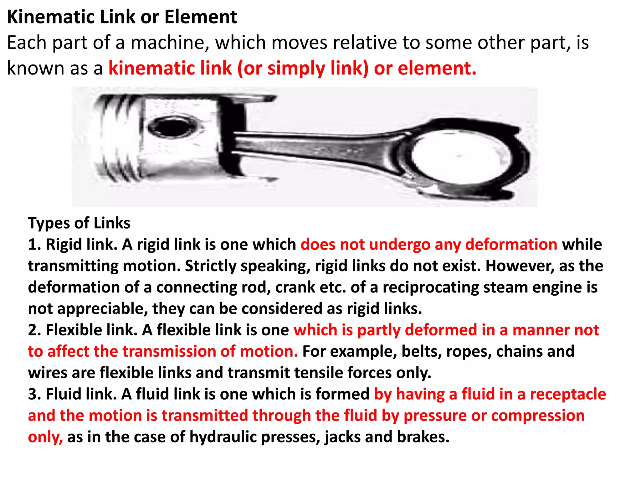
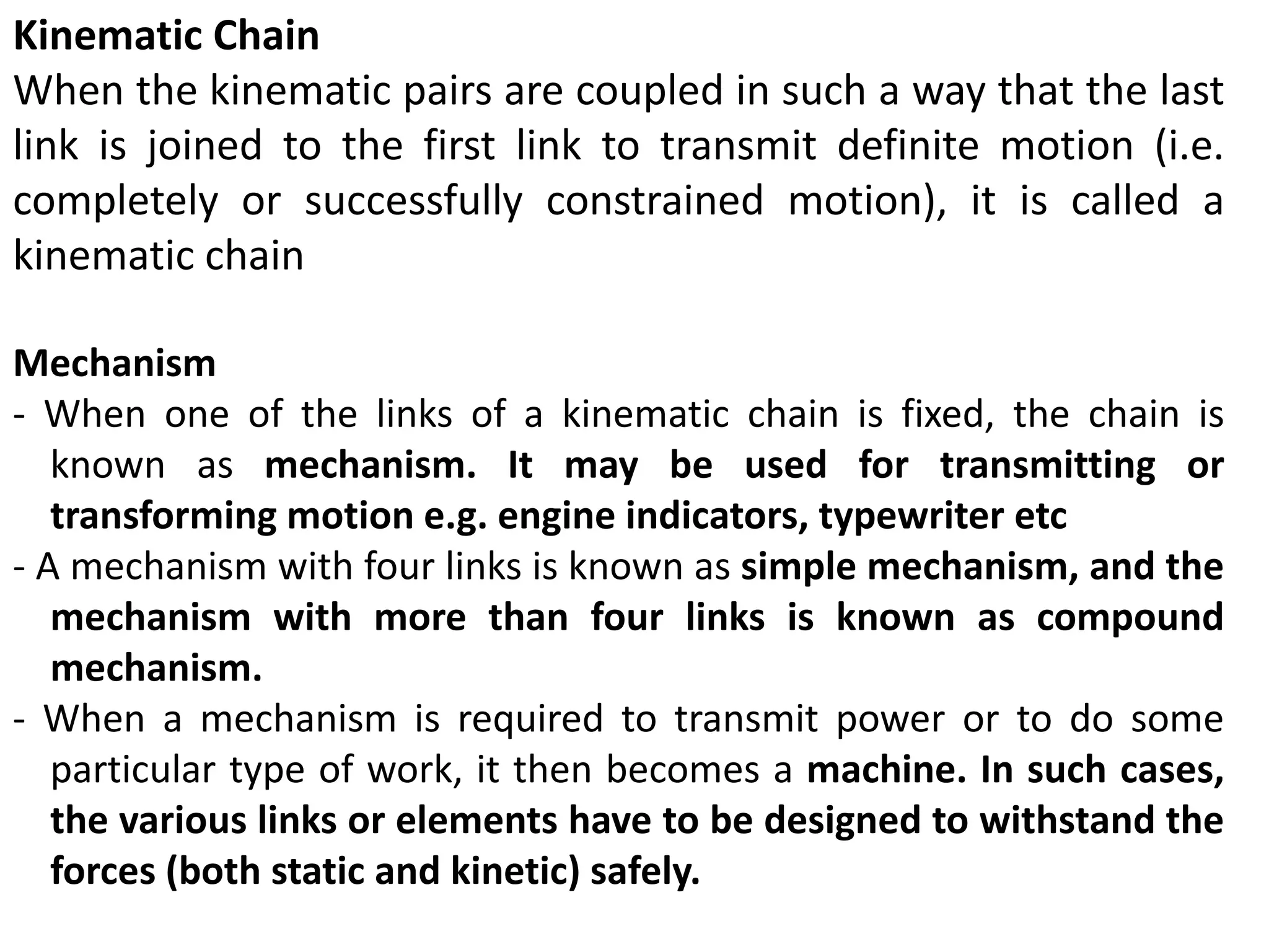
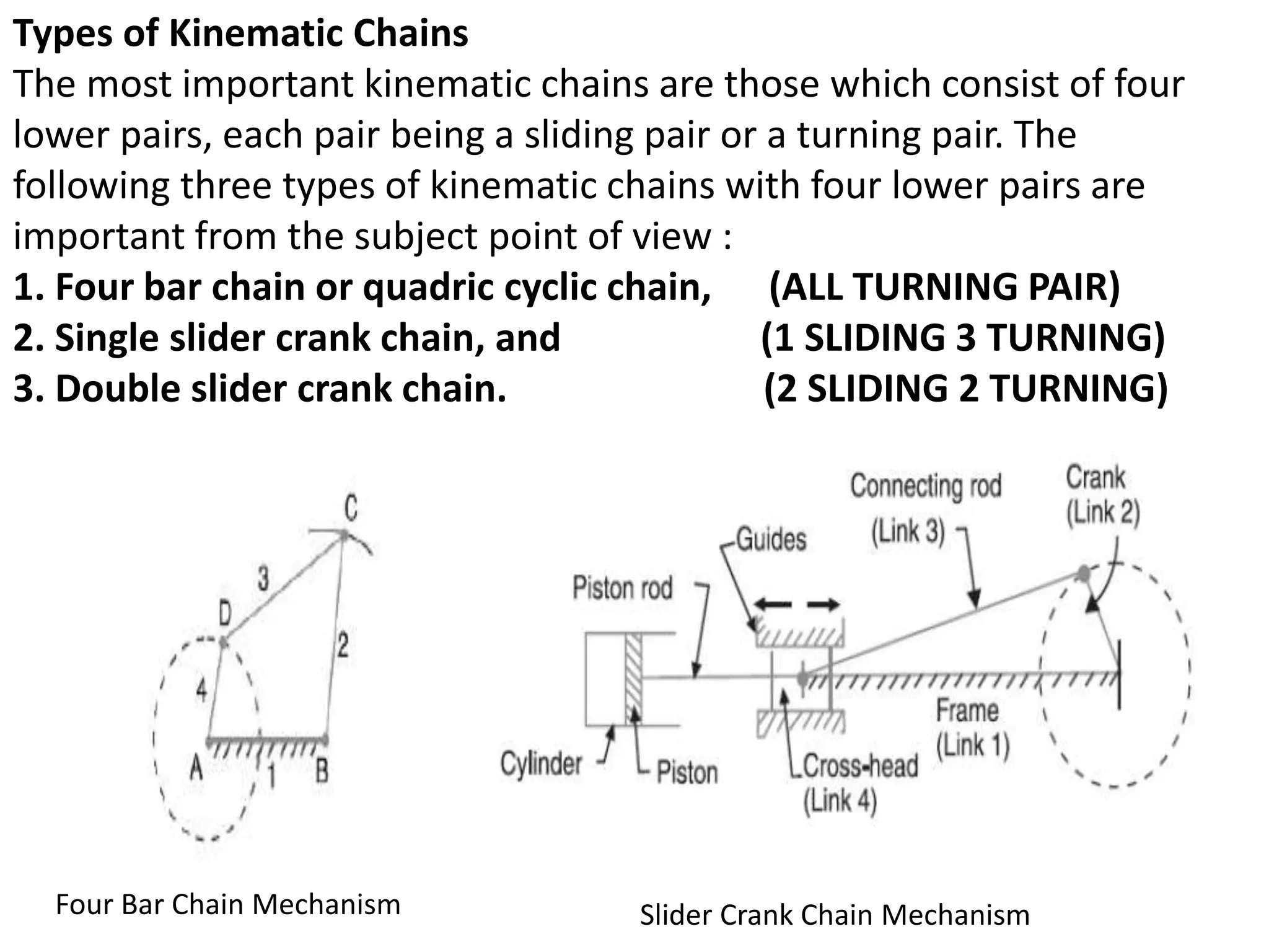
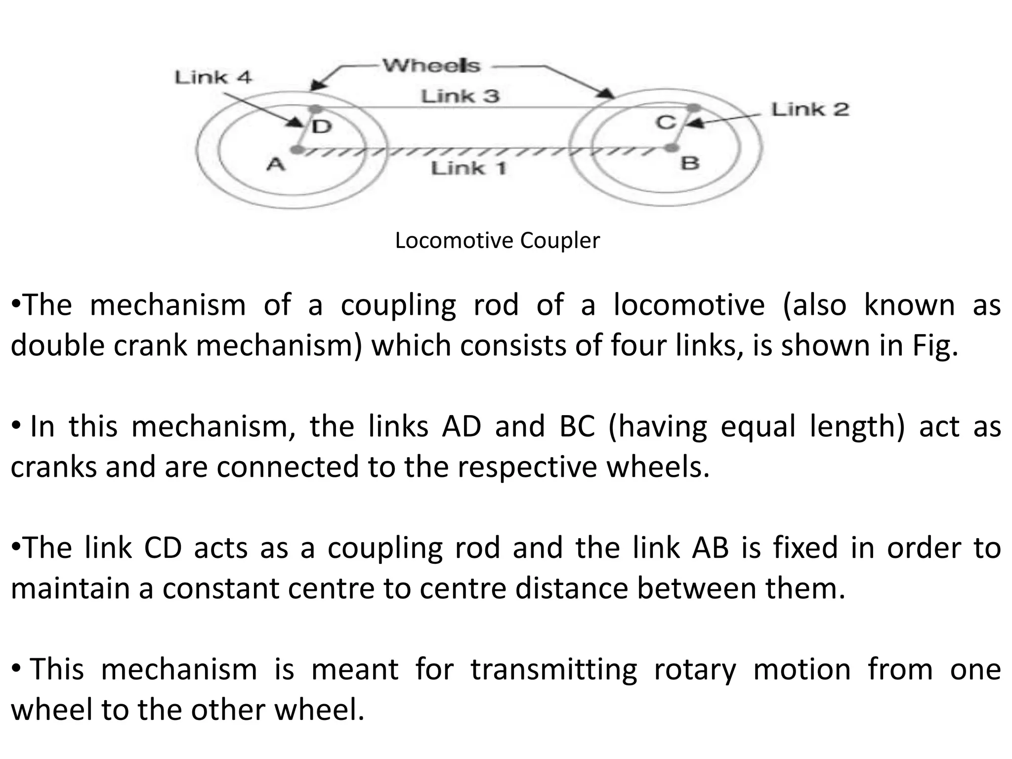
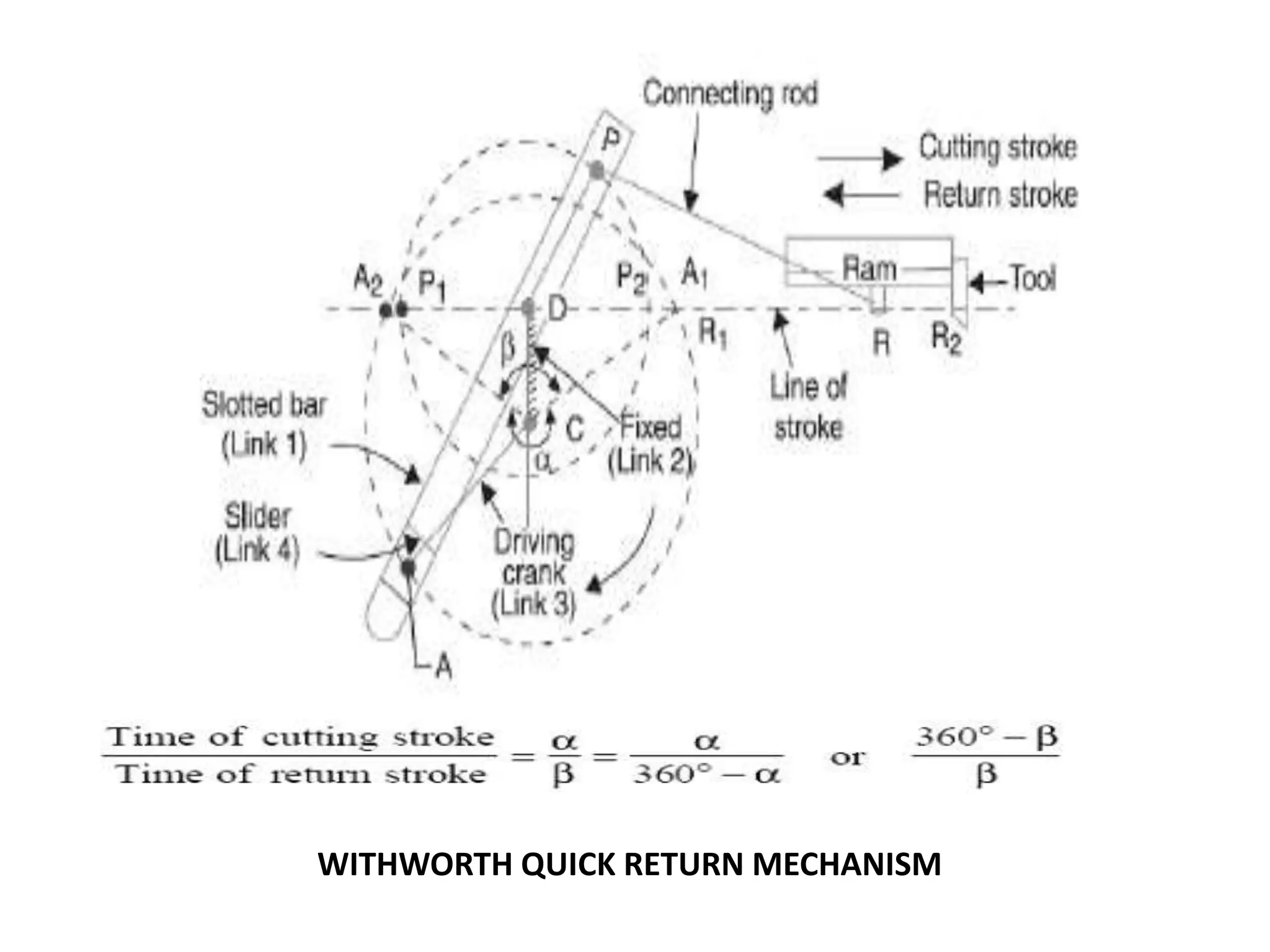
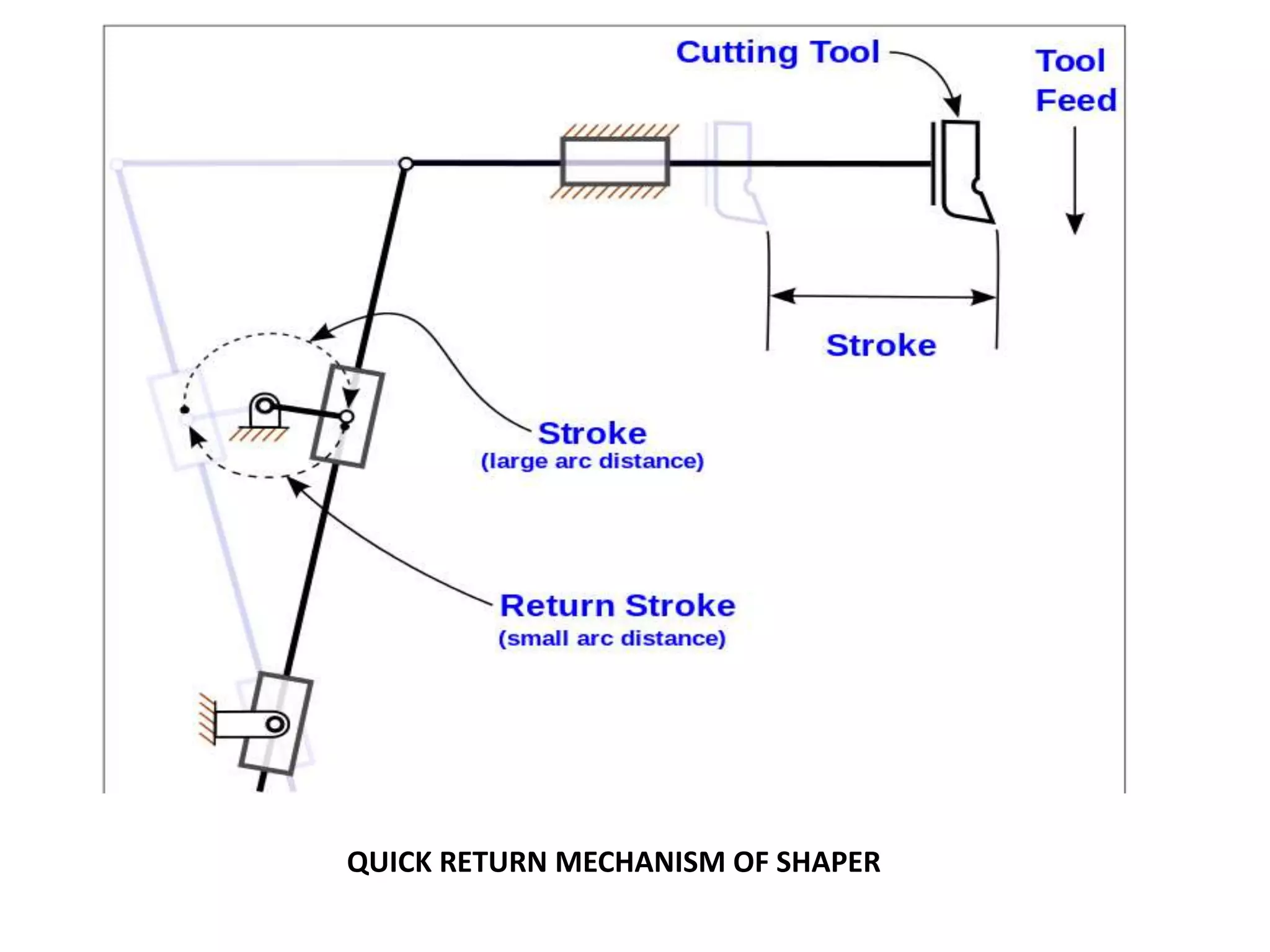
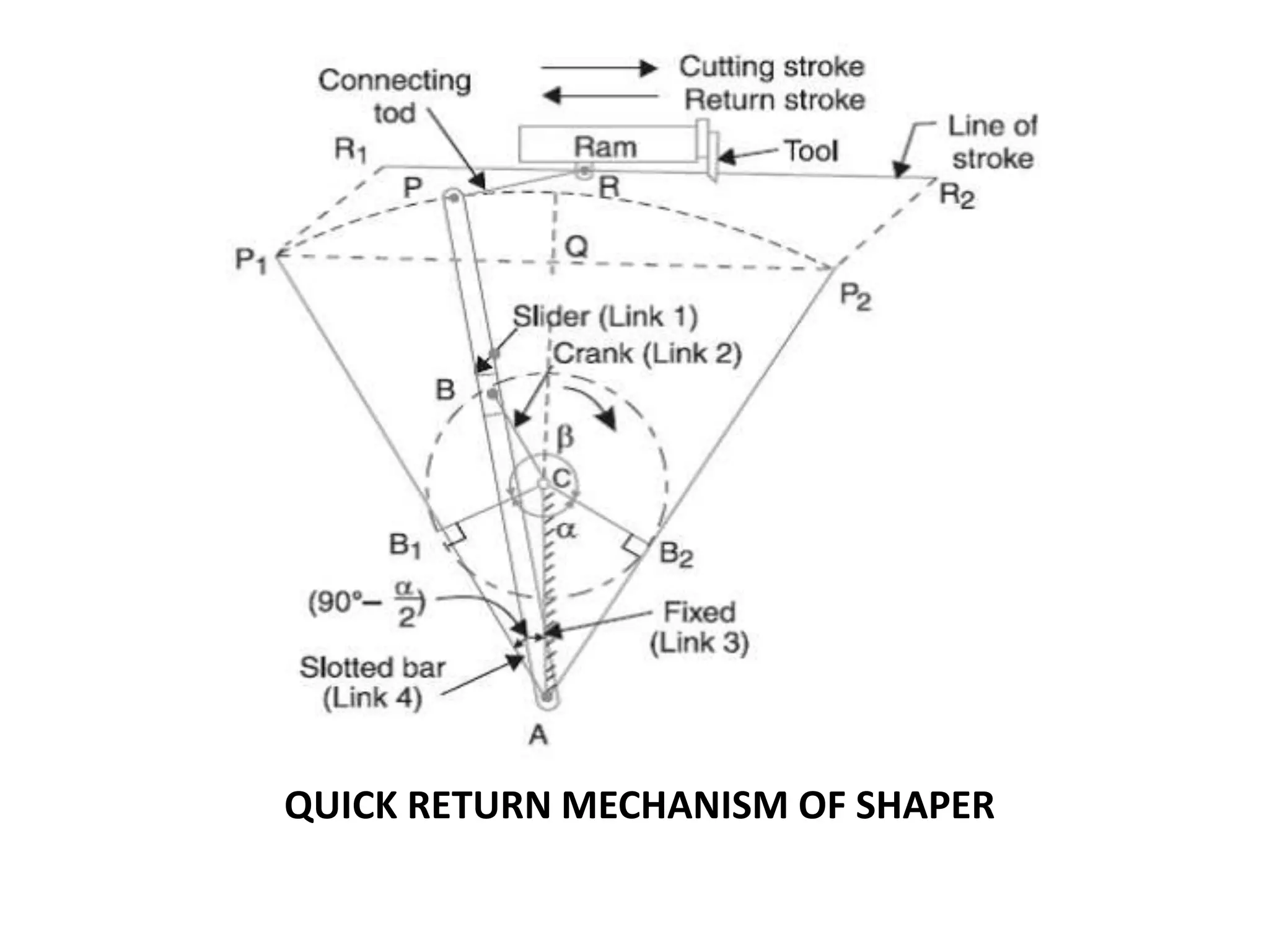
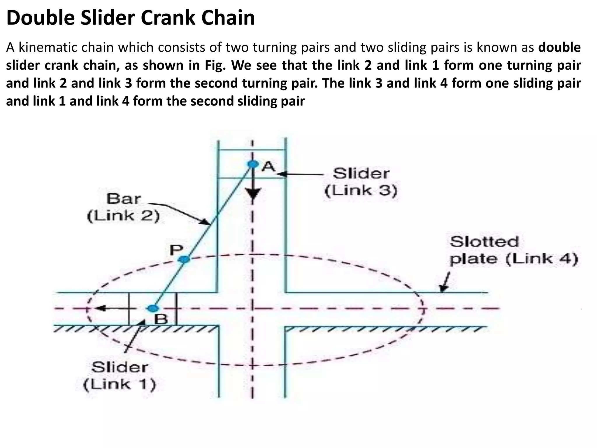
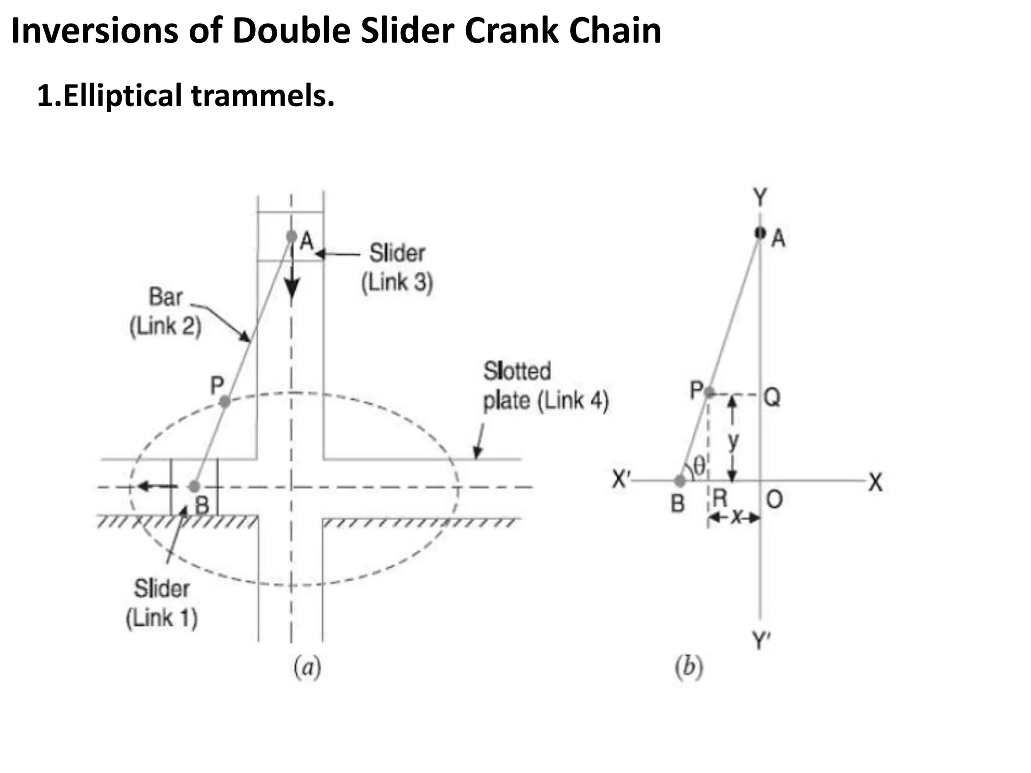
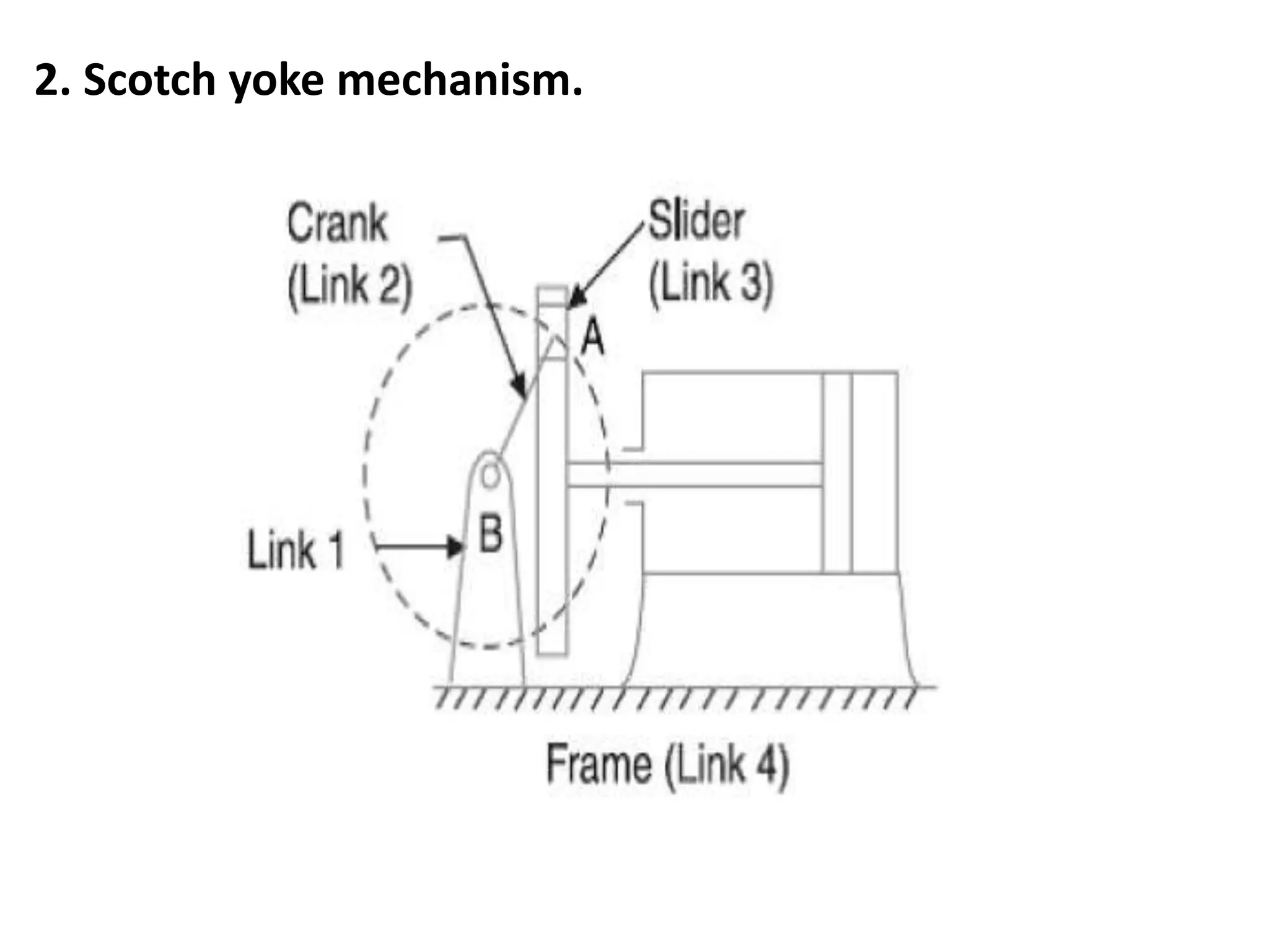
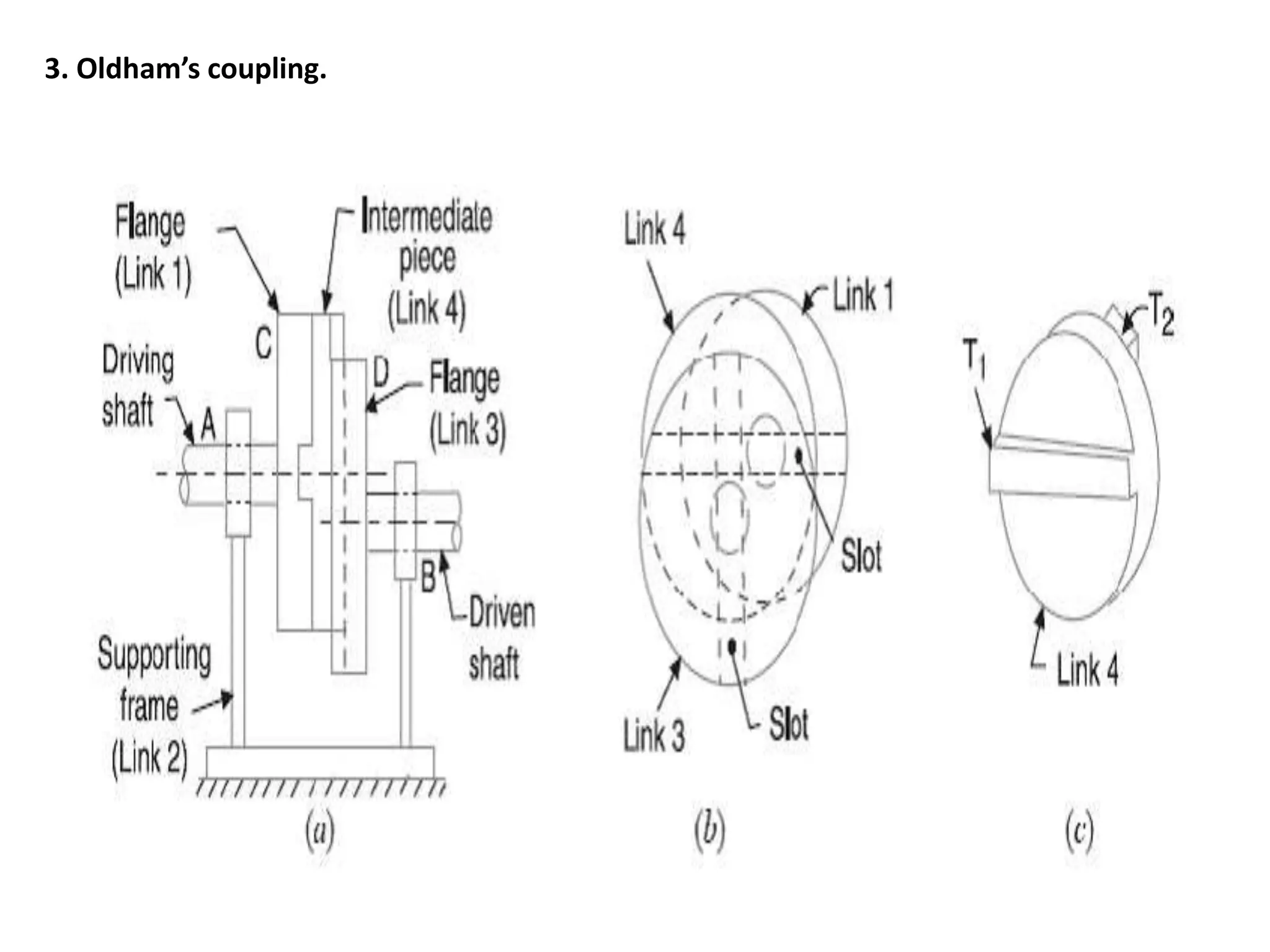
THEORY OF MACHINE (22438)
CHAPTER 01: FUNDAMENTALS OF
TYPES OF MECHANISMS (14 MARKS)
CO 438.01: STUDENTS CAN ABLE IDENTIFY VARIOUS LINKS IN
POPULAR MECHANISM
MR. MORE G.A.
LECTURER (TSSM BSCOER POLYTECHNIC NARHE PUNE -41)
1.1 KINEMATICS OF MACHINES
• What Is Theory of Machines ?
Definition : The subject Theory of Machines
may be defined as that branch of
Engineering-science, which deals with the
study of relative motion between the various
parts of a machine, and forces which act on
them.
Sub-divisions
1. Kinematics. It is that branch of Theory of Machines which deals
with the relative motion between the various parts of the
machines.
2. Dynamics. It is that branch of Theory of Machines which deals
with the forces and their effects, while acting upon the
machine parts in motion.
3. Kinetics. It is that branch of Theory of Machines which deals
with the inertia forces which arise from the combined effect of
the mass and motion of the machine parts.
4. Statics. It is that branch of Theory of Machines which deals with
the forces and their effects while the machine parts are at rest.
The mass of the parts is assumed to be negligible.
Kinematic Link or Element
Each part of a machine, which moves relative to some other part, is
known as a kinematic link (or simply link) or element.
Types of Links
1. Rigid link. A rigid link is one which does not undergo any deformation while
transmitting motion. Strictly speaking, rigid links do not exist. However, as the
deformation of a connecting rod, crank etc. of a reciprocating steam engine is
not appreciable, they can be considered as rigid links.
2. Flexible link. A flexible link is one which is partly deformed in a manner not
to affect the transmission of motion. For example, belts, ropes, chains and
wires are flexible links and transmit tensile forces only.
3. Fluid link. A fluid link is one which is formed by having a fluid in a receptacle
and the motion is transmitted through the fluid by pressure or compression
only, as in the case of hydraulic presses, jacks and brakes.
Structure
It is an assemblage of a number of resistant bodies (known as members)
having no relative motion between them and meant for carrying loads
having straining action. A railway bridge, a roof truss, machine frames
etc., are the examples of a structure.
Difference Between a Machine and a Structure :
1. The parts of a machine move relative to one another, whereas the
members of a structure do not move relative to one another.
2. A machine transforms the available energy into some useful work,
whereas in a structure no energy is transformed into useful work.
3. The links of a machine may transmit both power and motion, while
the members of a structure transmit forces only.
Kinematic Pair
The two links or elements of a machine, when in contact with each
other, are said to form a pair. If the relative motion between them is
completely or successfully constrained (i.e. in a definite direction), the
pair is known as kinematic pair
Types of Constrained Motions
1. Completely constrained motion. When the motion between a pair is
limited to a definite direction irrespective of the direction of force applied,
then the motion is said to be a completely constrained motion.
For example, the piston and cylinder (in a steam engine)
2. Incompletely constrained motion. When the motion between a pair can take
place in more than one direction, then the motion is called an incompletely
constrained motion.
3. Successfully constrained motion. When the motion between the
elements, forming a pair, is such that the constrained motion is not
completed by itself, but by some other means, then the motion is
said to be successfully constrained motion.
The motion of an I.C. engine valve (these are kept on their seat by a
spring) and the piston reciprocating inside an engine cylinder are
also the examples of successfully constrained motion.
Classification of Kinematic Pairs
1. According to the type of relative motion between the
elements.
(a) Sliding pair. When the two elements of a pair are
connected in such a way that one can only slide relative
to the other, the pair is known as a sliding pair. The
piston and cylinder, cross-head and guides of a
reciprocating steam engine, ram and its guides in shaper,
tail stock on the lathe bed etc. are the examples of a
sliding pair.
(b) Turning pair. When the two elements of a pair are
connected in such a way that one can only turn or
revolve about a fixed axis of another link, the pair is
known as turning pair. A shaft with collars at both ends
fitted into a circular hole.
(c) Rolling pair. When the two elements of a pair are
connected in such a way that one rolls over another
fixed link, the pair is known as rolling pair. Ball and
roller bearings are examples of rolling pair.
(d) Screw pair. When the two elements of a pair are
connected in such a way that one element can turn
about the other by screw threads, the pair is known as
screw pair. The lead screw of a lathe with nut, and bolt
with a nut are examples of a screw pair.
(e) Spherical pair. When the two elements of a pair are connected in
such a way that one element (with spherical shape) turns or
swivels about the other fixed element, the pair formed is called a
spherical pair. The ball and socket joint, attachment of a car
mirror, pen stand etc., are the examples of a spherical pair.
2. According to the type of contact between the elements. The
kinematic pairs according to
the type of contact between the elements may be classified as
discussed below :
(a) Lower pair. When the two elements of a pair have a surface
contact when relative motion takes place and the surface of one
element slides over the surface of the other, the pair formed is
known as lower pair. It will be seen that sliding pairs, turning pairs
and screw pairs form lower pairs.
(b) Higher pair. When the two elements of a pair have a line or point
contact when relative motion takes place and the motion between
the two elements is partly turning and partly sliding, then the pair
is known as higher pair. A pair of friction discs, toothed gearing,
belt and rope drives, ball and roller bearings and cam and follower
are the examples of higher pairs.
HIGHER PAIR LOWER PAIR
Kinematic Chain
When the kinematic pairs are coupled in such a way that the last
link is joined to the first link to transmit definite motion (i.e.
completely or successfully constrained motion), it is called a
kinematic chain
Mechanism
- When one of the links of a kinematic chain is fixed, the chain is
known as mechanism. It may be used for transmitting or
transforming motion e.g. engine indicators, typewriter etc
- A mechanism with four links is known as simple mechanism, and the
mechanism with more than four links is known as compound
mechanism.
- When a mechanism is required to transmit power or to do some
particular type of work, it then becomes a machine. In such cases,
the various links or elements have to be designed to withstand the
forces (both static and kinetic) safely.
Types of Kinematic Chains
The most important kinematic chains are those which consist of four
lower pairs, each pair being a sliding pair or a turning pair. The
following three types of kinematic chains with four lower pairs are
important from the subject point of view :
1. Four bar chain or quadric cyclic chain, (ALL TURNING PAIR)
2. Single slider crank chain, and (1 SLIDING 3 TURNING)
3. Double slider crank chain. (2 SLIDING 2 TURNING)
Four Bar Chain Mechanism Slider Crank Chain Mechanism
1.2 INVERSION of KINEMATIC CHAINS and their materials
Def. Of Inversion: Method of obtaining different mechanisms
by fixing different links in a kinematic chain, is known as
inversion of the mechanism
Inversions of Four Bar Chain -:
i) Locomotive Coupler
ii) Beam Engine
iii) Pantograph
Locomotive Coupler
•The mechanism of a coupling rod of a locomotive (also known as
double crank mechanism) which consists of four links, is shown in Fig.
• In this mechanism, the links AD and BC (having equal length) act as
cranks and are connected to the respective wheels.
•The link CD acts as a coupling rod and the link AB is fixed in order to
maintain a constant centre to centre distance between them.
• This mechanism is meant for transmitting rotary motion from one
wheel to the other wheel.
Beam ENGINE
•A part of the mechanism of a beam engine (also known as crank
and lever mechanism) which consists of four links, is shown in Fig In
this mechanism, when the crank rotates about the fixed centre A,
the lever oscillates about a fixed centre D.
•The end E of the lever CDE is connected to a piston rod which
reciprocates due to the rotation of the crank. In other words, the
purpose of this mechanism is to convert rotary motion into
reciprocating motion.
PANTOGRAPH
A Pantograph is an instrument used to reproduce to an enlarged or a reduced scale and as
exactly as possible the path described by a given point. (See Fig.)
The link ABQ is parallel to link OC and OA is parallel to link BC. A line is drawn joining O to Q. It
cuts BC at point P.
It will be seen that points Q and P describe similar paths but to different scales.
For the paths to be similar the essential requirement is that triangle OPC should be similar or
triangle BPQ for all positions.
For another position when point P has moved to P’ in the process of tracing the path of a circle,
it is seen that Q also traced the path of a circle from Q to Q’. The ratio
INVERSION OF SINGLE SLIDER CRANK CHAIN
SINGLE SLIDER CRANK CHAIN
The link 1 corresponds to the frame of the engine, which is
fixed. The link 2 corresponds to the crank ; link 3
corresponds to the connecting rod and link 4 corresponds
to cross-head. As the crank rotates, the cross-head
reciprocates in the guides and thus the piston reciprocates
in the cylinder.
INVERSION
I) PENDULUM PUMP
II) ROTARY I.C. ENGINE MECHANISM
III) OSCILLATING CYLINDER ENGINE
IV) WITHWORTH QUICK RETURN MECHANISM
V) QUICK RETURN MECHANISM OF SHAPER
PENDULUM PUMP
In this mechanism, the inversion is obtained by fixing the cylinder or
link 4 (i.e. sliding pair), as shown in Fig. In this case, when the crank
(link 2) rotates, the connecting rod (link 3) oscillates about a pin
pivoted to the fixed link 4 at A and the piston attached to the piston
rod (link 1) reciprocates. The duplex pump which is used to supply
feed water to boilers have two pistons attached to link 1, as shown
in Fig.
ROTARY IC ENGINE MECHANISM
Sometimes back, rotary internal combustion engines were
used in aviation. But now-a-days gas turbines are used in its
place. It consists of seven cylinders in one plane and
all revolves about fixed centre D, as shown in Fig. while the
crank (link 2) is fixed. In this mechanism, when the
connecting rod (link 4) rotates, the piston (link 3)
reciprocates inside the cylinders forming link 1.
OSCILLATING CYLINDER MECHANISM
The arrangement of oscillating cylinder engine mechanism, as
shown in Fig. is used to convert reciprocating motion into
rotary motion. In this mechanism, the link 3 forming the
turning pair is fixed.
The link 3 corresponds to the connecting rod of a reciprocating
steam engine mechanism. When the crank (link 2) rotates, the
piston attached to piston rod (link 1) reciprocates and the
cylinder (link 4) oscillates about a pin pivoted to the fixed link
at A.
WITHWORTH QUICK RETURN MECHANISM
QUICK RETURN MECHANISM OF SHAPER
Double Slider Crank Chain
A kinematic chain which consists of two turning pairs and two sliding pairs is known as double
slider crank chain, as shown in Fig. We see that the link 2 and link 1 form one turning pair
and link 2 and link 3 form the second turning pair. The link 3 and link 4 form one sliding pair
and link 1 and link 4 form the second sliding pair
Inversions of Double Slider Crank Chain
1.Elliptical trammels.
2. Scotch yoke mechanism.
3. Oldham’s coupling.
SUMMER 2019
1) Define term Kinetics
2) List different types of kinematic pairs
3) Draw scotch yoke mechanism
4) Draw sketch of locomotive coupler
5) Name suitable mechanism for following: i) Lifting water from well ii)Connecting misaligned
shaft iii) Convert rotary motion into reciprocating iv)Maintain constant rotary motion
between two elements
6) Draw labelled diagram of Crank & slotted lever Quick return mechanism

Fundamentals and types of mechanisms

  • 1.
    THEORY OF MACHINE(22438) CHAPTER 01: FUNDAMENTALS OF TYPES OF MECHANISMS (14 MARKS) CO 438.01: STUDENTS CAN ABLE IDENTIFY VARIOUS LINKS IN POPULAR MECHANISM MR. MORE G.A. LECTURER (TSSM BSCOER POLYTECHNIC NARHE PUNE -41)
  • 2.
    1.1 KINEMATICS OFMACHINES • What Is Theory of Machines ? Definition : The subject Theory of Machines may be defined as that branch of Engineering-science, which deals with the study of relative motion between the various parts of a machine, and forces which act on them.
  • 3.
    Sub-divisions 1. Kinematics. Itis that branch of Theory of Machines which deals with the relative motion between the various parts of the machines. 2. Dynamics. It is that branch of Theory of Machines which deals with the forces and their effects, while acting upon the machine parts in motion. 3. Kinetics. It is that branch of Theory of Machines which deals with the inertia forces which arise from the combined effect of the mass and motion of the machine parts. 4. Statics. It is that branch of Theory of Machines which deals with the forces and their effects while the machine parts are at rest. The mass of the parts is assumed to be negligible.
  • 4.
    Kinematic Link orElement Each part of a machine, which moves relative to some other part, is known as a kinematic link (or simply link) or element. Types of Links 1. Rigid link. A rigid link is one which does not undergo any deformation while transmitting motion. Strictly speaking, rigid links do not exist. However, as the deformation of a connecting rod, crank etc. of a reciprocating steam engine is not appreciable, they can be considered as rigid links. 2. Flexible link. A flexible link is one which is partly deformed in a manner not to affect the transmission of motion. For example, belts, ropes, chains and wires are flexible links and transmit tensile forces only. 3. Fluid link. A fluid link is one which is formed by having a fluid in a receptacle and the motion is transmitted through the fluid by pressure or compression only, as in the case of hydraulic presses, jacks and brakes.
  • 5.
    Structure It is anassemblage of a number of resistant bodies (known as members) having no relative motion between them and meant for carrying loads having straining action. A railway bridge, a roof truss, machine frames etc., are the examples of a structure. Difference Between a Machine and a Structure : 1. The parts of a machine move relative to one another, whereas the members of a structure do not move relative to one another. 2. A machine transforms the available energy into some useful work, whereas in a structure no energy is transformed into useful work. 3. The links of a machine may transmit both power and motion, while the members of a structure transmit forces only.
  • 6.
    Kinematic Pair The twolinks or elements of a machine, when in contact with each other, are said to form a pair. If the relative motion between them is completely or successfully constrained (i.e. in a definite direction), the pair is known as kinematic pair Types of Constrained Motions 1. Completely constrained motion. When the motion between a pair is limited to a definite direction irrespective of the direction of force applied, then the motion is said to be a completely constrained motion. For example, the piston and cylinder (in a steam engine)
  • 7.
    2. Incompletely constrainedmotion. When the motion between a pair can take place in more than one direction, then the motion is called an incompletely constrained motion. 3. Successfully constrained motion. When the motion between the elements, forming a pair, is such that the constrained motion is not completed by itself, but by some other means, then the motion is said to be successfully constrained motion. The motion of an I.C. engine valve (these are kept on their seat by a spring) and the piston reciprocating inside an engine cylinder are also the examples of successfully constrained motion.
  • 8.
    Classification of KinematicPairs 1. According to the type of relative motion between the elements. (a) Sliding pair. When the two elements of a pair are connected in such a way that one can only slide relative to the other, the pair is known as a sliding pair. The piston and cylinder, cross-head and guides of a reciprocating steam engine, ram and its guides in shaper, tail stock on the lathe bed etc. are the examples of a sliding pair. (b) Turning pair. When the two elements of a pair are connected in such a way that one can only turn or revolve about a fixed axis of another link, the pair is known as turning pair. A shaft with collars at both ends fitted into a circular hole.
  • 9.
    (c) Rolling pair.When the two elements of a pair are connected in such a way that one rolls over another fixed link, the pair is known as rolling pair. Ball and roller bearings are examples of rolling pair. (d) Screw pair. When the two elements of a pair are connected in such a way that one element can turn about the other by screw threads, the pair is known as screw pair. The lead screw of a lathe with nut, and bolt with a nut are examples of a screw pair. (e) Spherical pair. When the two elements of a pair are connected in such a way that one element (with spherical shape) turns or swivels about the other fixed element, the pair formed is called a spherical pair. The ball and socket joint, attachment of a car mirror, pen stand etc., are the examples of a spherical pair.
  • 11.
    2. According tothe type of contact between the elements. The kinematic pairs according to the type of contact between the elements may be classified as discussed below : (a) Lower pair. When the two elements of a pair have a surface contact when relative motion takes place and the surface of one element slides over the surface of the other, the pair formed is known as lower pair. It will be seen that sliding pairs, turning pairs and screw pairs form lower pairs. (b) Higher pair. When the two elements of a pair have a line or point contact when relative motion takes place and the motion between the two elements is partly turning and partly sliding, then the pair is known as higher pair. A pair of friction discs, toothed gearing, belt and rope drives, ball and roller bearings and cam and follower are the examples of higher pairs.
  • 12.
  • 13.
    Kinematic Chain When thekinematic pairs are coupled in such a way that the last link is joined to the first link to transmit definite motion (i.e. completely or successfully constrained motion), it is called a kinematic chain Mechanism - When one of the links of a kinematic chain is fixed, the chain is known as mechanism. It may be used for transmitting or transforming motion e.g. engine indicators, typewriter etc - A mechanism with four links is known as simple mechanism, and the mechanism with more than four links is known as compound mechanism. - When a mechanism is required to transmit power or to do some particular type of work, it then becomes a machine. In such cases, the various links or elements have to be designed to withstand the forces (both static and kinetic) safely.
  • 14.
    Types of KinematicChains The most important kinematic chains are those which consist of four lower pairs, each pair being a sliding pair or a turning pair. The following three types of kinematic chains with four lower pairs are important from the subject point of view : 1. Four bar chain or quadric cyclic chain, (ALL TURNING PAIR) 2. Single slider crank chain, and (1 SLIDING 3 TURNING) 3. Double slider crank chain. (2 SLIDING 2 TURNING) Four Bar Chain Mechanism Slider Crank Chain Mechanism
  • 15.
    1.2 INVERSION ofKINEMATIC CHAINS and their materials Def. Of Inversion: Method of obtaining different mechanisms by fixing different links in a kinematic chain, is known as inversion of the mechanism Inversions of Four Bar Chain -: i) Locomotive Coupler ii) Beam Engine iii) Pantograph
  • 16.
    Locomotive Coupler •The mechanismof a coupling rod of a locomotive (also known as double crank mechanism) which consists of four links, is shown in Fig. • In this mechanism, the links AD and BC (having equal length) act as cranks and are connected to the respective wheels. •The link CD acts as a coupling rod and the link AB is fixed in order to maintain a constant centre to centre distance between them. • This mechanism is meant for transmitting rotary motion from one wheel to the other wheel.
  • 17.
    Beam ENGINE •A partof the mechanism of a beam engine (also known as crank and lever mechanism) which consists of four links, is shown in Fig In this mechanism, when the crank rotates about the fixed centre A, the lever oscillates about a fixed centre D. •The end E of the lever CDE is connected to a piston rod which reciprocates due to the rotation of the crank. In other words, the purpose of this mechanism is to convert rotary motion into reciprocating motion.
  • 18.
  • 19.
    A Pantograph isan instrument used to reproduce to an enlarged or a reduced scale and as exactly as possible the path described by a given point. (See Fig.) The link ABQ is parallel to link OC and OA is parallel to link BC. A line is drawn joining O to Q. It cuts BC at point P. It will be seen that points Q and P describe similar paths but to different scales. For the paths to be similar the essential requirement is that triangle OPC should be similar or triangle BPQ for all positions. For another position when point P has moved to P’ in the process of tracing the path of a circle, it is seen that Q also traced the path of a circle from Q to Q’. The ratio
  • 20.
    INVERSION OF SINGLESLIDER CRANK CHAIN SINGLE SLIDER CRANK CHAIN The link 1 corresponds to the frame of the engine, which is fixed. The link 2 corresponds to the crank ; link 3 corresponds to the connecting rod and link 4 corresponds to cross-head. As the crank rotates, the cross-head reciprocates in the guides and thus the piston reciprocates in the cylinder.
  • 21.
    INVERSION I) PENDULUM PUMP II)ROTARY I.C. ENGINE MECHANISM III) OSCILLATING CYLINDER ENGINE IV) WITHWORTH QUICK RETURN MECHANISM V) QUICK RETURN MECHANISM OF SHAPER
  • 22.
    PENDULUM PUMP In thismechanism, the inversion is obtained by fixing the cylinder or link 4 (i.e. sliding pair), as shown in Fig. In this case, when the crank (link 2) rotates, the connecting rod (link 3) oscillates about a pin pivoted to the fixed link 4 at A and the piston attached to the piston rod (link 1) reciprocates. The duplex pump which is used to supply feed water to boilers have two pistons attached to link 1, as shown in Fig.
  • 23.
    ROTARY IC ENGINEMECHANISM Sometimes back, rotary internal combustion engines were used in aviation. But now-a-days gas turbines are used in its place. It consists of seven cylinders in one plane and all revolves about fixed centre D, as shown in Fig. while the crank (link 2) is fixed. In this mechanism, when the connecting rod (link 4) rotates, the piston (link 3) reciprocates inside the cylinders forming link 1.
  • 24.
    OSCILLATING CYLINDER MECHANISM Thearrangement of oscillating cylinder engine mechanism, as shown in Fig. is used to convert reciprocating motion into rotary motion. In this mechanism, the link 3 forming the turning pair is fixed. The link 3 corresponds to the connecting rod of a reciprocating steam engine mechanism. When the crank (link 2) rotates, the piston attached to piston rod (link 1) reciprocates and the cylinder (link 4) oscillates about a pin pivoted to the fixed link at A.
  • 25.
  • 26.
  • 27.
  • 28.
    Double Slider CrankChain A kinematic chain which consists of two turning pairs and two sliding pairs is known as double slider crank chain, as shown in Fig. We see that the link 2 and link 1 form one turning pair and link 2 and link 3 form the second turning pair. The link 3 and link 4 form one sliding pair and link 1 and link 4 form the second sliding pair
  • 29.
    Inversions of DoubleSlider Crank Chain 1.Elliptical trammels.
  • 30.
    2. Scotch yokemechanism.
  • 31.
  • 32.
    SUMMER 2019 1) Defineterm Kinetics 2) List different types of kinematic pairs 3) Draw scotch yoke mechanism 4) Draw sketch of locomotive coupler 5) Name suitable mechanism for following: i) Lifting water from well ii)Connecting misaligned shaft iii) Convert rotary motion into reciprocating iv)Maintain constant rotary motion between two elements 6) Draw labelled diagram of Crank & slotted lever Quick return mechanism