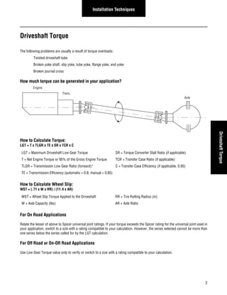
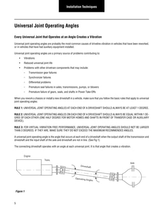
SlideShare a Scribd company logo
DRIVELINE INSTALLATION 
J3311-1-DSSP 
AUGUST 2008 
Supersedes 
J3311-1-HVTSS, Dated 
February 2005
Safety Precautions 
General Safety Information 
To prevent injury to yourself and /or damage to the equipment: 
• Read carefully all owners manuals, service manuals, 
and/or other instructions. 
• Always follow proper procedures and use proper 
tools and safety equipment. 
• Be sure to receive proper training. 
• Never work alone while under a vehicle or while re-pairing 
or maintaining equipment. 
• Always use proper components in applications for 
which they are approved. 
• Be sure to assemble components properly. 
• Never use worn-out or damaged components. 
• Always block any raised or moving device that may 
injure a person working on or under a vehicle. 
• Never operate the controls of the power take-off or 
other driven equipment from any position that could 
result in getting caught in the moving machinery. 
WARNING: ROTATING DRIVESHAFTS 
• Rotating auxiliary driveshafts are dangerous. You can 
snag clothes, skin, hair, hands, etc. This can cause 
serious injury or death. 
• Do not go under the vehicle when the engine is run-ning. 
• Do not work on or near an exposed shaft when engine 
is running. 
• Shut off engine before working on power take-off or 
driven equipment. 
• Exposed rotating driveshafts must be guarded. 
WARNING: GUARDING AUXILIARY DRIVESHAFTS 
We strongly recommend that a power take-off and a directly 
mounted pump be used to eliminate the auxiliary driveshaft 
whenever possible. If an auxiliary driveshaft is used and re-mains 
exposed after installation, it is the responsibility of the 
vehicle designer and PTO installer to install a guard. 
WARNING: USING SET SCREWS 
Auxiliary driveshafts may be installed with either recessed or 
protruding set screws. If you choose a square head set screw, 
you should be aware that it will protrude above the hub of the 
yoke and may be a point where clothes, skin, hair, hands, etc. 
could be snagged. A socket head set screw, which may not 
protrude above the hub of the yoke, does not permit the same 
amount of torquing as does a square head set screw. Also a 
square head set screw, if used with a lock wire, will prevent 
loosening of the screw caused by vibration. Regardless of the 
choice made with respect to a set screw, an exposed rotating 
auxiliary driveshaft must be guarded. 
WARNING: THIS SYMBOL WARNS OF POSSIBLE 
PERSONAL INJURY.
Table of Contents 
Table of Contents 
Introduction .............................................................................................................................................................. 1 
Driveshaft Torque ...................................................................................................................................................... 2 
Common Causes of Vibrations .................................................................................................................................. 3 
Universal Joint Operating Angles .............................................................................................................................. 5 
Eliminating Compound Angle Induced Vibrations ..................................................................................................... 11 
Multiple Shaft Installations ........................................................................................................................................ 13 
Mounting a Midship-Mounted PTO, Pump, or Auxiliary Transmission ...................................................................... 16 
Maximum Safe Operating Speed ............................................................................................................................... 18
1 
General Information 
Introduction 
This brochure is intended for: 
• Installers who install Spicer driveshafts into an application where the transmission and axle are not in direct line with 
each other, causing the driveshaft universal joints to operate at an angle. 
• Anyone experiencing vibration problems with their application or their vehicle that driveshaft assembly balancing will not 
correct. 
• Truck Equipment Distributors who: 
• Re-work a chassis to change the wheel base. 
• Install a midship mounted power take-off or fire pump. 
• Mount any other PTO-driven device such as a blower, hydraulic pump, or hydraulic motor. 
Universal joint failures, as a rule, are of a progressive nature, which, when they occur, generally accelerate rapidly resulting in a 
mass of melted trunnions and bearings. 
Some recognizable signs of universal joint deterioration are: 
1. Vibrations - Driver should report to maintenance. 
2. Universal joint looseness - End play across bearings. 
3. Universal joint discoloration due to excessive heat build-up. 
4. Inability to purge all four trunnion seals when re-lubing universal joint. 
Items 2) thru 4) should be checked at re-lube cycle and, if detected, reported to the maintenance supervisor for investigation. 
Experience with universal joint failures has shown that a significant majority are related to lubricating film breakdown. This may 
be caused by a lack of lubricant, inadequate lube quality for the application, inadequate initial lubrication, or failure to lubricate 
properly and often enough. 
Failures which are not the result of lubrication film breakdown are associated with the installation, angles and speeds, and manu-facturing 
discrepancies. 
Driveshaft failures through torque, fatigue, and bending are associated with overload, excessively high universal joint angles, and 
drive shaft lengths excessive for operating speeds.
2 
Installation Techniques 
Driveshaft Torque 
Driveshaft Torque 
The following problems are usually a result of torque overloads: 
Twisted driveshaft tube 
Broken yoke shaft, slip yoke, tube yoke, flange yoke, end yoke 
Broken journal cross 
How much torque can be generated in your application? 
Engine 
Trans. 
How to Calculate Torque: 
LGT = T x TLGR x TE x SR x TCR x C 
Axle 
LGT = Maximum Driveshaft Low Gear Torque SR = Torque Converter Stall Ratio (if applicable) 
T = Net Engine Torque or 95% of the Gross Engine Torque TCR = Transfer Case Ratio (if applicable) 
TLGR = Transmission Low Gear Ratio (forward)* C = Transfer Case Efficiency (if applicable, 0.95) 
TE = Transmission Efficiency (automatic = 0.8; manual = 0.85) 
How to Calculate Wheel Slip: 
WST = (.71 x W x RR) / (11.4 x AR) 
WST = Wheel Slip Torque Applied to the Driveshaft RR = Tire Rolling Radius (in) 
W = Axle Capacity (lbs) AR = Axle Ratio 
For On Road Applications 
Relate the lesser of above to Spicer universal joint ratings. If your torque exceeds the Spicer rating for the universal joint used in 
your application, switch to a size with a rating compatible to your calculation. However, the series selected cannot be more than 
one series below the series called for by the LGT calculation. 
For Off Road or On-Off Road Applications 
Use Low Gear Torque value only to verify or switch to a size with a rating compatible to your calculation.
Series Specification 
1310, 1330 .375 oz-in total at each end of shaft * 
1350, 1410 .500 oz-in total at each end of shaft * 
1480 - 1880 1.00 oz-in for each ten pounds of driveshaft weight divided proportionally at each end of shaft 
* Passenger Car, Light Truck, Van, and SUV only. Industrial, Mobile Off-Highway, PTO, etc. same as 1480 - 1880. 
3 
Installation Techniques 
Common Causes of Vibrations 
The three most common causes of driveshaft vibration are: Driveshaft Imbalance, Critical Speed, and Universal Joint Operating 
Angles. 
Driveshaft Imbalance 
Eliminate the potential for balance problems before you undertake any other measures. 
A driveshaft on a vehicle usually rotates at a higher rate of speed than the tire. For that reason, like tires, driveshafts should be 
balanced. 
Any time you build or rework a driveshaft, make sure it is dynamically balanced at, 3000 RPM for Light Duty or 2500 RPM for 
Heavy Duty, to the following specifications: 
Critical Speed 
Every driveshaft has a critical speed. Critical speed is the point at which a rotating driveshaft begins to bow off its normal rotating 
centerline. 
Driveshafts begin to vibrate as they approach critical speed. If they are operated at near critical speed for an extended period, they 
often fail. This can damage the vehicle and possibly injure persons nearby. 
As a driveshaft fabricator or installer, you are responsible for checking the safe operating speed of any driveshaft you fabricate or 
specify into an application. Make sure it will not operate at a speed higher than Spicer’s recommended safe operating speed. Use 
Spicer Calculator (P/N J 3253) to determine safe operating speed. 
Checking for a Possible Critical Speed Problem 
Here is what you must do to make sure you won’t have a critical speed problem: 
• Determine the safe operating speed of the driveshaft you want to use in your application. Insert the tube diameter and 
center-to-center installed length of the shaft you want to use into a Spicer Safe Operating Speed Calculator (P/N. J3253). 
The calculator will tell you the safe operating speed of the shaft you have chosen. 
• Determine the NORMAL and MAXIMUM POSSIBLE operating speed of the driveshaft. 
REMEMBER: 
• On vehicles with a standard transmission that have a 1:1 direct drive high gear and no overdrive, MAXIMUM POS-SIBLE 
driveshaft RPM is the same as the maximum possible ENGINE RPM. 
• On vehicles that have an overdrive transmission, MAXIMUM POSSIBLE driveshaft RPM is higher than maximum 
possible ENGINE RPM.
4 
Installation Techniques 
Common Causes of 
Vibration 
Maximum Possible Driveshaft RPM 
To calculate the maximum possible driveshaft RPM in vehicles having an overdrive transmission, divide the maximum possible 
engine RPM by the overdrive ratio. (See examples below.) 
Example 1: 
Max. engine RPM: 2100 
Overdrive ratio: .79 
2100/.79 = 2658 maximum possible driveshaft RPM 
Example 2: 
Max. engine RPM 6000 
Overdrive ratio: .66 
6000/.66 - 9091 maximum possible driveshaft RPM 
Compare the maximum possible driveshaft RPM with the safe operating speed determined from the Safe Operating Speed Calcu-lator. 
If the maximum possible driveshaft RPM meets or exceeds the safe operating speed determined from the calculator, you 
must do whatever is required to raise the critical speed of the driveshaft you have chosen for the application. 
Sample Specification: 
To specify a driveshaft for the application described in Example 1 above, compare the safe operating speed for the driveshaft se-lected 
with the maximum possible driveshaft RPM calculated (2658 RPM). Make sure the safe operating speed of the driveshaft 
is greater than 2658 RPM. 
Changing the Safe Operating Speed of a Driveshaft 
A driveshaft’s safe operating speed can be raised by increasing its tube diameter or by shortening the installed center-to-center 
length of the driveshaft. Changing the installed length of a driveshaft will require the use of multiple driveshafts with center bear-ings. 
Important: The critical speed of an assembly can be affected by driveshaft imbalance, improper universal joint operating angles, 
or improperly phased driveshafts. (A properly phased driveshaft has the in-board yokes of the shaft in line with each other.) Each 
of the above items will tend to lower the true critical speed from the values shown on the calculator. 
Since critical speed can ultimately cause driveshaft failure, it is extremely important to be very precise in all applications.
5 
Installation Techniques 
Universal Joint Operating Angles 
Every Universal Joint that Operates at an Angle Creates a Vibration 
Universal joint operating angles are probably the most common causes of driveline vibration in vehicles that have been reworked, 
or in vehicles that have had auxiliary equipment installed. 
Universal joint operating angles are a primary source of problems contributing to: 
• Vibrations 
• Reduced universal joint life 
• Problems with other drivetrain components that may include: 
- Transmission gear failures 
- Synchronizer failures 
- Differential problems 
- Premature seal failures in axles, transmissions, pumps, or blowers 
- Premature failure of gears, seals, and shafts in Power Take-Offs 
When you rework a chassis or install a new driveshaft in a vehicle, make sure that you follow the basic rules that apply to universal 
joint operating angles: 
RULE 1: UNIVERSAL JOINT OPERATING ANGLES AT EACH END OF A DRIVESHAFT SHOULD ALWAYS BE AT LEAST 1 DEGREE. 
RULE 2: UNIVERSAL JOINT OPERATING ANGLES ON EACH END OF A DRIVESHAFT SHOULD ALWAYS BE EQUAL WITHIN 1 DE-GREE 
OF EACH OTHER (ONE HALF DEGREE FOR MOTOR HOMES AND SHAFTS IN FRONT OF TRANSFER CASE OR AUXILIARY 
DEVICE). 
RULE 3: FOR VIRTUAL VIBRATION FREE PERFORMANCE, UNIVERSAL JOINT OPERATING ANGLES SHOULD NOT BE LARGER 
THAN 3 DEGREES. IF THEY ARE, MAKE SURE THEY DO NOT EXCEED THE MAXIMUM RECOMMENDED ANGLES. 
A universal joint operating angle is the angle that occurs at each end of a driveshaft when the output shaft of the transmission and 
driveshaft and the input shaft of the axle and driveshaft are not in line. (See Fig 1) 
The connecting driveshaft operates with an angle at each universal joint. It is that angle that creates a vibration. 
Engine 
Figure 1 
Trans. 
Axle 
Driveshaft 
Operating Angles
6 
Installation Techniques 
U-Joint Operating Angles 
Reducing and Canceling Vibration 
A key point to remember about universal joint operating angles: To reduce the amount of vibration, the angles on each end of a 
driveshaft should always be SMALL. 
To cancel an angle vibration, the universal joint operating angles need to be EQUAL within 1 degree at each end of a driveshaft. 
On motor home applications and auxiliary transmission installations, the tolerance is 1/2 degree. (See Fig 2) 
Figure 2 
Trans. 
Axle 
Make angles small 
Make angles equal
Figure 3 
7 
Installation Techniques 
Single Plane and Compound Universal Joint Operating Angles 
There are two types of universal joint operating angles: Single Plane and Compound. 
Single Plane 
Single Plane angles occur when the transmission and axle components are in line when viewed from either the top or side, but 
not both. 
Determining the universal joint operating angle in an application where the components are in line when viewed from the top, but 
not in line when viewed from the side, is as simple as measuring the slope of the components in the side view, and adding or 
subtracting those slopes to determine the angle. (See Fig. 3) 
These angles should be small and equal within 1 degree. 
DanaDana Spicer Anglemaster 
a 
Trans. 
1 2 
Spicer 
Anglemaster 
Bubbletype 
protractor 
Spicer Anglemaster 
Dana 
3 4 
5 
6 
b c 
d 
Engine 
Axle 
Spicer Anglemaster 
DanaDana 
Axle 
Legend 
Anglemaster Spicer 
Dana 
Spicer Anglemaster 
DanaDana 
Spicer Anglemaster 
Dana 
The most convenient way to determine universal joint angles in the side view is through the use of a Spicer Anglemaster™ or a 
bubble type protractor. 
Using an Anglemaster or a bubble protractor, record inclination angles of drivetrain components. Set Anglemaster or protractor 
on machined surfaces of engine, transmission, axle, or on machined lugs of transmission and axle yoke(s). 
Note: Universal joint angles can change significantly in a loaded situation. Therefore, check vehicle loaded and unloaded to achieve 
the accepted angle cancellation. 
Example: 
Engine-Transmission Output 4°30’ Down (1) 
Main Driveshaft 7°00’ Down (2) 
Input 1st Rear Axle 4°00’ Up (Input Shaft Nose Up) (3) 
Output 1st Rear Axle 4°00’ Down (4) 
Inter-axle Shaft 7°00’ Down (5) 
Input 2nd Rear Axle 4°15’ Up (Pinion Shaft Nose Up) (6) 
Note: If inclination of driveshaft is opposite connecting component, add angles to obtain the universal joint operating angle. 
Angle a = (2) - (1) = 7°00’ - 4°30’ = 2°30’ (2.50°) 
Angle b = (2) - (3) = 7°00’ - 4°00’ = 3°00’ (3.00°) 
Angle c = (5) - (4) = 7°00’ - 4°00’ = 3°00’ (3.00°) 
Angle d = (5) - (6) = 7°00’ - 4°15’ = 2°45’ (2.75°)
8 
Installation Techniques 
U-Joint Operating Angles 
Determining the universal joint operating angles on a driveshaft that is straight when viewed from the side and offset when viewed 
from the top requires the use of a special chart (See Angle Chart). In this type of application, the centerlines of the connected 
components must be parallel when viewed from the top as shown. These angles also should be small and equal within 1 degree. 
(See Fig. 4) 
Figure 4 
Axle 
x 
B 
Angles in Top View 
Engine 
Trans. 
x 
A 
Measure dimensions "A" and "B" shown in figure 4. Use the instructions in the angle chart below to determine the size of the angle. 
Look at the Angle Chart and note that the smaller the offset, the smaller the resultant angle. 
To reduce the possibility of vibration, keep any offset between connected points to a minimum. 
There are two things you can do to always make sure Single Plane angles are SMALL and EQUAL: Make sure the transmission 
and axle are mounted so their centerlines are parallel when viewed from both the side and the top. Make sure the offset between 
them is small in both views. 
ANGLE CHART 
6.0o 
5.0o 
4.0o 
2.0o 
1.0o 
9.0o 
8.0o 
11.0 o 
14.0 o 
10 20 30 40 50 60 70 
12 
11 
10 
9 
8 
7 
6 
5 
4 
3 
2 
1 
3.0o 
7.0o 
10.0 o 
12.0 o 
13.0 o 
15.0 o 
Dimension A (inches) 
Dimension B (inches) 
Operating Angle x 
For Driveshafts Having An Angle in the Top View 
Example: (See Fig. 4) 
1. Measure Dimension "A" 
2. Determine Dimension "B" 
Using chart, determine angle "x" by 
finding the intersection point of a 
dimension "A" vertical line and a 
dimension "B" horixontal line.
Engine 
Figure 5 
9 
Installation Techniques 
Compound Angles 
Compound universal joint operating angles occur when the transmission and axle are not in line when viewed from BOTH the top 
and side. Their centerlines, however, are parallel in both views. (See Fig. 5) 
Axle 
Trans. 
Engine 
Trans. 
Axle 
Top View 
Parallel Centerlines 
Driveshaft 
Side View 
Parallel Centerlines 
When you have a compound angle, you have to calculate the "True Universal Joint Operating Angle" of each universal joint. It is 
the True Universal Joint Operating Angle that must meet the three rules shown on page 5.
10 
Installation Techniques 
U-Joint Operating Angles 
True Universal Joint Operating Angle 
The True Universal Joint Operating Angle, which must be calculated for each end of the shaft with compound angles, is a combi-nation 
of the universal joint operating angle in the top view, as determined from the chart, and the measured universal joint oper-ating 
angle in the side view. 
To determine the true universal joint operating angle for one end of a shaft, (compound angle C° in the formula shown in Fig. 6) 
insert the universal joint operating angle measurement obtained in the side view and the universal joint operating angle obtained 
from the chart into the formula. 
Figure 6 
T 
o 
(2.15 ) 
o 
(2.50 ) 
Angle in Top View (from Chart) SideView 
S 
o 
Compound Angle (C ) = 
o 
T + S 2 2 
T = 2.15 (A calculated angle) 
S = 2.5 o 
(The measured angle) 
C = 2.152 + 2.5 2 
C = 10.873 
C = 3.3 o 
(True operating angle) 
Do the same for the other end of the shaft. Compare the resultant calculated universal joint operating angle for each end. They 
should be EQUAL within 1 degree. If they’re not, the driveshaft will vibrate.
Figure 7 
11 
Installation Techniques 
Eliminating Compound Angle Induced Vibrations 
Compound universal joint operating angles are one of the most common causes of driveline vibration. To avoid theses problems, 
remember these important points: 
• When setting up an application that requires compound universal joint operating angles, always keep the centerlines of 
the transmission and axle parallel in both views. 
• Always keep the offset between their horizontal and vertical centerlines small. 
Note: Centerlines of transmission and axle must be parallel in both top and side views to use this method of determining true 
universal joint operating angle. Please contact Spicer Driveshaft Engineering if you have an application where the compo-nents 
cannot be installed with their centerlines parallel. 
If adjustments must be made to the system: 
• Install shims between the axle housing and springs to rotate the axle input yoke to change operating angles. 
• Change operating angle on torque arm type suspensions by lengthening or shortening torque arms. 
• Raise, lower, or shift side-to-side a pump, blower, or other piece of auxiliary equipment to change operating angles. 
Note: It is important to remember to keep the centerlines of two components that are connected by a driveshaft parallel in both 
the top and side views, so the operating angles will ALWAYS be equal. 
Axle 
Engine 
Trans. 
Engine 
Trans. 
Axle 
Keep Angles Equal 
and Offset Small 
Top View 
Side View 
Less Than 3 
Small Offset 
o
12 
Installation Techniques 
Compound Angle 
Vibrations 
Angle Size 
The magnitude of a vibration created by a universal joint operating angle is proportional to the size of the universal joint operating 
angle. Spicer Engineers recommend true universal joint operating angles of 3 degrees or less. 
Obtain the true universal joint operating angle, as explained above, and if it is greater than 3 degrees, compare it to this chart. 
Driveshaft Maximum Interaxle 
RPM Operating Angle Parallel Intersecting 
5000 3.2° - - 
4500 3.7° - - 
4000 4.2° 3.8° 3.8° 
3500 5.0° 4.4° 4.4° 
3000 5.8° 5.1° 4.8° 
2500 7.0° 6.0° 4.8° 
2000 8.7° 6.0° 4.8° 
1500 11.5° 6.0° 4.8° 
The angles shown on this chart are the maximum universal joint operating angles recommended by Spicer Engineers and are di-rectly 
related to the speed of the driveshaft. Any universal joint operating angle greater than 3 degrees will lower universal joint 
life and may cause a vibration. Remember to check maximum safe driveshaft RPM by using the Spicer Safe Operating Speed Cal-culator.
Figure 8 
13 
Installation Techniques 
Multiple Shaft Installations 
Multiple Shaft Set Up Recommendations 
In general, multiple shaft installations follow the same guidelines, except there are different recommendations for setting up the 
driveline: 
• For a 2-shaft application, set up the first coupling shaft (sometimes called a jackshaft) so that the universal joint operating 
angle that occurs at the transmission end is 1 to 1-1/2 degrees. (See Fig. 8) 
• Try to avoid building a compound universal joint operating angle into the first coupling shaft by installing it in line with 
the transmission. 
• If it ends up being compound, make sure the true universal joint operating angle, determined by using the information 
mentioned earlier, is 1 to 1-1/2 degrees. 
Install or tilt the axle so it is mounted on the same angle as the first coupling shaft (the centerlines of the axle and the first coupling 
shaft will be parallel). 
Note: BY FOLLOWING THIS PROCEDURE, THE UNIVERSAL JOINT OPERATING ANGLE AT EACH END OF THE LAST SHAFT WILL 
AUTOMATICALLY BE EQUAL. (See Fig. 9) 
1 to 1-1/2 
True Angle Center 
Bearing 
o o
14 
Installation Techniques 
Multiple Shaft 
Installations 
Figure 9 
Adjust the axle to be 
on the same angle 
as the first shaft 
If there is an offset in the installation of the axle, make sure it does not create too large of a compound universal joint operating 
angle. Whenever possible, mount the axle directly in line with the first coupling shaft (when viewed from the top). 
Check the actual universal joint operating angle at the rear of the first coupling shaft. If it is less than 1º and the transmission 
universal joint operating angle is greater than 1.5º, rotate the end yoke at the center bearing position so that the ears of the yoke 
are 90º to the ears of the tube yoke on the transmission end of the coupling shaft. (See Fig. 10) As an alternative, rotate the slip 
yoke on the driveshaft 90º if the slip spline has 16 teeth. 
Figure 10 
True angle 
1 to 1-1/2 
Center 
Bearing 
These angles will 
automatically be equal 
o o 
Rotate 
Yoke 
On same angle 
If this angle is 
less than 1 o 
, rotate yoke 
as shown
15 
Installation Techniques 
On applications having more than two shafts, mount the first coupling shaft as outlined in the preceding example, and each addi-tional 
coupling shaft at a 1 to 1-1/2 degree universal joint operating angle to the previous coupling shaft. 
Install or tilt the axle to the same angle as the last fixed coupling shaft so the centerline of the axle and the last fixed coupling shaft 
are parallel. 
Note: THIS ASSURES THE UNIVERSAL JOINT OPEARTING ANGLE AT EACH END OF THE LAST SHAFT WILL AUTOMATICALLY 
BE EQUAL (See Fig. 11). 
Figure 11 
1 to 1-1/2 Angle o o 
Shaft 1 
Shaft 2 
Check size 
of these angles. 
Do not exceed 
maximums. 
Mount on same 
angle as shaft #2
16 
Installation Techniques 
Midship Mounted 
Components 
Mounting a Midship-Mounted PTO, Pump, or Auxiliary Transmission 
When installing a midship-mounted PTO, auxiliary transmission, or midship-mounted pump into the main driveline of a vehicle, 
install it at the same angle as the transmission. Keep the offset to a minimum to reduce universal joint operating angles. 
Note: Do not make the universal joint operating angle less than 1/2 degree. 
Before bolting the device in place, check the universal joint operating angles that occur at each end of the driveshaft. They must 
be 1 to 1-1/2 degrees and they must be equal to within 1/2 degree for this type of application. 
If the device ends up being installed in direct line with the transmission, with little or no universal joint operating angle on the 
joints, raise or lower it so there is enough offset to create the required 1 to 1-1/2 degree universal joint operating angle on each 
end of the driveshaft. (See Fig. 12) 
Figure 12 
If there is only one driveshaft between the device and the rear axle, rotate the rear axle (using shims in the appropriate place) so 
it is the same angle as the device. This makes the universal joint operating angle at each end of the driveshaft equal (See Fig. 13). 
Check the size of the universal joint operating angles to determine if they meet recommendations. 
Figure 13 
1/20 minimum 
10 to 1-1/20 recommended 
30 maximum 
Equal within 1/20 
Install at same angle 
and in-line in top view 
Auxiliary 
Device 
Install at same angle 
and in-line in top view 
Check size of 
these angles 
Rotate axle to same 
angle as Auxiliary 
Device 
1/20 minimum 
10 to 1-1/20 recommended 
30 maximum 
Equal within 1/20
Figure 14 
17 
Installation Techniques 
If there is more than one driveshaft between the device and the rear axle, install the driveshaft as outlined earlier with a 1 to 
1-1/2 degree universal joint operating angle on the input end of each shaft. Then rotate the axle so it is on the same angle as the 
last fixed shaft. The universal joint operating angle on each end of the last shaft will automatically be equal. (See Fig. 14) 
1/20 minimum 
10 to 1-1/20 recommended 
30 maximum 
Equal within 1/20 
Install at same angle 
and in-line in top view 
1 to 1-1/2 angle minimum o o 
Mounting a Remote-Driven Pump, Blower, or Similar Device 
Check these angles. 
3 recommended o 
Mount on same angle 
rotate axle if necessary 
Remote mounted-pumps, blowers, or similar devices are usually driven by a side, top, or bottom-mounted PTO and use an aux-iliary 
driveshaft. 
Many times these devices are mounted to the vehicle frame or cross member. The usual method of mounting, where the driven 
device is mounted parallel with the ground without regard to the mounted angle of the PTO, will produce a vibration that may cause 
failure of the PTO, pump, blower, or other driven device. 
Any remote driven device must be mounted parallel and in line, if possible, with the PTO. 
To select the appropriate auxiliary driveshaft for these types of applications, you should consider proper torque, safe operating 
speed (which is different than the critical speed for tubular driveshafts), and angularity. (See Maximum Safe Operating Speed Chart 
on page 18). 
An auxiliary driveshaft must be capable of transmitting the maximum torque and RPM required by the driven equipment. For most 
low-torque applications operating at less than 1200 RPM, solid bar-stock constructed driveshafts are adequate. For applications 
requiring additional torque or RPMs, tubular shafts should be fabricated.
TUBING MAXIMUM INSTALLED LENGTH (IN INCHES) FOR GIVEN RPM 
Diameter Centerline to Centerline of Joints for a Two Joint Assembly 
& or 
Wall Thickness Centerline of Joint to Centerline of Center Bearing for a Joint and Shaft 
W - Welded RPM - Revolutions Per Minute 
S - Seamless 1000 1500 2000 2500 3000 3500 4000 4500 5000 5500 6000 
1.750" x .065" W 82" 67" 58" 52" - - - - - - - 
1.250" x .095" S 64" 52" 45" 40" 37" 34" 32" - - - - 
2.500" x .083" W 87" 70" 62" 55" 50" 45" 43" 41" 39" 37" 35" 
3.000" x .083" W - - 85" 76" 70" 64" 60" 57" 54" 51" 49" 
SOLID SHAFT DIAMETER 
.750" 42" 35" 30" 27" 25" - - - - - - 
.812" 44" 36" 31" 28" 26" - - - - - - 
.875" 46" 37" 32" 29" 27" - - - - - - 
1.000" 49" 40" 35" 31" 28" - - - - - - 
1.250" 55" 45" 39" 35" 32" - - - - - - 
18 
Installation Techniques 
Maximum Operating 
Speed 
Maximum Safe Operating Speed 
MAXIMUM OPERATING SPEED* BY TUBE SIZE, SOLID SHAFT SIZE, AND LENGTH 
*(For speeds over 6000 RPM, contact Spicer Universal Joint Division Engineering) 
To prevent premature wear, auxiliary driveshaft breakage, and possible injury to people or equipment, be aware of the critical 
speed of these types of driveshafts. Critical speed, explained earlier in this guide, is different for these solid shaft and small tube 
driveshafts. 
Refer to the chart above for maximum safe operating speed information on these types of shafts. 
If the chart indicates that the critical speed may be a problem, use multiple shafts. Be sure to use support bearings where neces-sary 
and set up the true universal joint operating angles as indicated earlier in this guide. 
As with all driveshafts, auxiliary driveshafts should be: 
• Carefully installed to minimize vibrations caused by incorrect universal joint operating angles 
• Capable of absorbing shock loads 
• Capable of changing length as needed 
• Guarded so as to prevent inadvertent entanglement
19 
Installation Techniques 
Special Notes Regarding Auxiliary Driveshafts 
WARNING: Working on or near an auxiliary driveshaft when the engine is running is extremely dangerous and should be avoided. 
You can snag clothes, skin, hair, hands, etc. This can cause serious injury or death. 
• Shut off engine before working on power take-off or driven equipment. 
• Do not go under the vehicle when the engine is running. 
• Do not engage or disengage driven equipment by hand from under the vehicle when the engine is running. 
• Fasteners should be properly selected and torqued to the manufacturer’s specifications. 
• If a setscrew protrudes above the hub of an end yoke, you may want to replace it with a recessed (Allen-type) setscrew. 
• If you decide that a recessed setscrew does not have enough holding power for your application and you must use a 
protruding setscrew, be sure no one can come in contact with the rotating driveshaft or the protruding setscrew. 
• Exposed rotating driveshafts must be guarded! 
• Lubricate auxiliary driveshafts according to manufacturer’s specifications.
J3311-1-DSSP 
8/08 
Printed in U.S.A 
© Dana Limited 2008. 
All rights reserved. 
Dana Holding Corporation 
Spicer Service Parts - Canada 
5095 South Service Road 
Beamsville, Ontario LOR 1BO 
Dana Holding Corporation 
Spicer Service Parts 
PO Box 321 
Toledo, Ohio 43697-0321 
1-800-SAY-DANA (729-3262) 
www.spicerparts.com 
Dana Holding Corporation 
Spicer Service Parts - International 
(419) 861-6325

More Related Content

What's hot

Mechanical seal presentation 1
Mechanical seal presentation 1Mechanical seal presentation 1
Mechanical seal presentation 1
EMMANUEL ESSEN
 
7 steering mechanisms
7 steering mechanisms7 steering mechanisms
7 steering mechanisms
shaikusmanshag
 
Presentation on internal combustion engine components
Presentation on internal combustion  engine componentsPresentation on internal combustion  engine components
Presentation on internal combustion engine components
Er.Shailendra kumar
 
Halderman ch033 lecture
Halderman ch033 lectureHalderman ch033 lecture
Halderman ch033 lecturemcfalltj
 
Steering gearboxes
Steering gearboxesSteering gearboxes
Steering gearboxes
Pushpajeet .
 
Fluid flywheel
Fluid flywheelFluid flywheel
Fluid flywheel
Adarsh Kancherla
 
Piston presentation
Piston presentationPiston presentation
Piston presentation
Tejinderpal Singh
 
Universal joint
Universal jointUniversal joint
Universal joint
AhmedBasha41
 
Brakes
BrakesBrakes
Clutch materials
Clutch materialsClutch materials
Clutch materials
Hamimi Akmal
 
Ppt wheel-balancing
Ppt wheel-balancingPpt wheel-balancing
Ppt wheel-balancing
Sunit Neeli
 
3.layouts of automobile
3.layouts of automobile3.layouts of automobile
3.layouts of automobile
Yoga Sathish
 
Gearboxes in auto
Gearboxes in autoGearboxes in auto
Gearboxes in autoSam Cheng
 
Machine elements
Machine elementsMachine elements
Machine elements
AISSMS IOIT,PUNE
 
Bearing and Sliding contact bearings
Bearing and Sliding contact bearingsBearing and Sliding contact bearings
Bearing and Sliding contact bearings
dodi mulya
 
Gas turbine engine
Gas turbine engineGas turbine engine
Gas turbine engine
Uday Wankar
 
STEERING SYSTEM.pptx
STEERING SYSTEM.pptxSTEERING SYSTEM.pptx
STEERING SYSTEM.pptx
BablaBiswas1
 
2b9fc module iii steering system_ part-ii (2)
2b9fc module iii steering system_ part-ii (2)2b9fc module iii steering system_ part-ii (2)
2b9fc module iii steering system_ part-ii (2)
Tanvi Gautam
 
Gear Failure
Gear FailureGear Failure
Gear Failure
Himanshi Gupta
 
Gearbox in automobile
Gearbox  in automobile Gearbox  in automobile
Gearbox in automobile sgrsoni45
 

What's hot (20)

Mechanical seal presentation 1
Mechanical seal presentation 1Mechanical seal presentation 1
Mechanical seal presentation 1
 
7 steering mechanisms
7 steering mechanisms7 steering mechanisms
7 steering mechanisms
 
Presentation on internal combustion engine components
Presentation on internal combustion  engine componentsPresentation on internal combustion  engine components
Presentation on internal combustion engine components
 
Halderman ch033 lecture
Halderman ch033 lectureHalderman ch033 lecture
Halderman ch033 lecture
 
Steering gearboxes
Steering gearboxesSteering gearboxes
Steering gearboxes
 
Fluid flywheel
Fluid flywheelFluid flywheel
Fluid flywheel
 
Piston presentation
Piston presentationPiston presentation
Piston presentation
 
Universal joint
Universal jointUniversal joint
Universal joint
 
Brakes
BrakesBrakes
Brakes
 
Clutch materials
Clutch materialsClutch materials
Clutch materials
 
Ppt wheel-balancing
Ppt wheel-balancingPpt wheel-balancing
Ppt wheel-balancing
 
3.layouts of automobile
3.layouts of automobile3.layouts of automobile
3.layouts of automobile
 
Gearboxes in auto
Gearboxes in autoGearboxes in auto
Gearboxes in auto
 
Machine elements
Machine elementsMachine elements
Machine elements
 
Bearing and Sliding contact bearings
Bearing and Sliding contact bearingsBearing and Sliding contact bearings
Bearing and Sliding contact bearings
 
Gas turbine engine
Gas turbine engineGas turbine engine
Gas turbine engine
 
STEERING SYSTEM.pptx
STEERING SYSTEM.pptxSTEERING SYSTEM.pptx
STEERING SYSTEM.pptx
 
2b9fc module iii steering system_ part-ii (2)
2b9fc module iii steering system_ part-ii (2)2b9fc module iii steering system_ part-ii (2)
2b9fc module iii steering system_ part-ii (2)
 
Gear Failure
Gear FailureGear Failure
Gear Failure
 
Gearbox in automobile
Gearbox  in automobile Gearbox  in automobile
Gearbox in automobile
 

Viewers also liked

Universal joints
Universal jointsUniversal joints
Universal joints
Asheem Kumar Palo
 
universal joint
universal jointuniversal joint
universal joint
Mihir Dixit
 
Universal joint and intermittent motion mechanism
Universal joint and intermittent motion mechanism Universal joint and intermittent motion mechanism
Universal joint and intermittent motion mechanism
MichaelAzada
 
7 universal joint
7 universal joint7 universal joint
7 universal joint
shaikusmanshag
 
DESIGN ANALYSIS OF UNIVERSAL JOINT SHAFT FOR ROLLING MILLS
DESIGN ANALYSIS OF UNIVERSAL JOINT SHAFT FOR ROLLING MILLSDESIGN ANALYSIS OF UNIVERSAL JOINT SHAFT FOR ROLLING MILLS
DESIGN ANALYSIS OF UNIVERSAL JOINT SHAFT FOR ROLLING MILLS
Sughosh Deshmukh
 
KoM ppt unit1 pvpsit 2015 Basic Mechanisms
KoM ppt unit1 pvpsit 2015  Basic MechanismsKoM ppt unit1 pvpsit 2015  Basic Mechanisms
KoM ppt unit1 pvpsit 2015 Basic Mechanisms
kishorereddy_btech
 
Neoel gramm a taxi 2015 2016
Neoel gramm a taxi 2015 2016Neoel gramm a taxi 2015 2016
Neoel gramm a taxi 2015 2016
56ο Γυμνάσιο Αθήνας
 
Cardan shaft swf series
Cardan shaft swf seriesCardan shaft swf series
Cardan shaft swf series
august zeng
 
Universal joints
Universal jointsUniversal joints
Universal joints
Shiv Sahaya Shukla
 
Cam profile and indexing mechanism
Cam profile and indexing mechanismCam profile and indexing mechanism
Cam profile and indexing mechanismphysics101
 
Mechanisms
MechanismsMechanisms
Mechanisms
Yatin Singh
 
Driveshaft presentation 03
Driveshaft presentation 03Driveshaft presentation 03
Driveshaft presentation 03Franco Pezza
 
Driveshafts
DriveshaftsDriveshafts
Driveshafts
Rob Holt
 
06 разрезы (49)
06 разрезы (49)06 разрезы (49)
06 разрезы (49)Taygo
 
Basic mechanisms
Basic mechanismsBasic mechanisms
Basic mechanisms
Christopher Todd
 
Rack and pinion
Rack and pinionRack and pinion
Indexing and hashing
Indexing and hashingIndexing and hashing
Indexing and hashingJeet Poria
 
Design Like DaVinci
Design Like DaVinciDesign Like DaVinci
Design Like DaVinci
Brian Sullivan
 

Viewers also liked (20)

Universal joints
Universal jointsUniversal joints
Universal joints
 
Universal joints
Universal joints Universal joints
Universal joints
 
universal joint
universal jointuniversal joint
universal joint
 
Universal joint and intermittent motion mechanism
Universal joint and intermittent motion mechanism Universal joint and intermittent motion mechanism
Universal joint and intermittent motion mechanism
 
7 universal joint
7 universal joint7 universal joint
7 universal joint
 
DESIGN ANALYSIS OF UNIVERSAL JOINT SHAFT FOR ROLLING MILLS
DESIGN ANALYSIS OF UNIVERSAL JOINT SHAFT FOR ROLLING MILLSDESIGN ANALYSIS OF UNIVERSAL JOINT SHAFT FOR ROLLING MILLS
DESIGN ANALYSIS OF UNIVERSAL JOINT SHAFT FOR ROLLING MILLS
 
KoM ppt unit1 pvpsit 2015 Basic Mechanisms
KoM ppt unit1 pvpsit 2015  Basic MechanismsKoM ppt unit1 pvpsit 2015  Basic Mechanisms
KoM ppt unit1 pvpsit 2015 Basic Mechanisms
 
Neoel gramm a taxi 2015 2016
Neoel gramm a taxi 2015 2016Neoel gramm a taxi 2015 2016
Neoel gramm a taxi 2015 2016
 
Cardan shaft swf series
Cardan shaft swf seriesCardan shaft swf series
Cardan shaft swf series
 
Chap96
Chap96Chap96
Chap96
 
Universal joints
Universal jointsUniversal joints
Universal joints
 
Cam profile and indexing mechanism
Cam profile and indexing mechanismCam profile and indexing mechanism
Cam profile and indexing mechanism
 
Mechanisms
MechanismsMechanisms
Mechanisms
 
Driveshaft presentation 03
Driveshaft presentation 03Driveshaft presentation 03
Driveshaft presentation 03
 
Driveshafts
DriveshaftsDriveshafts
Driveshafts
 
06 разрезы (49)
06 разрезы (49)06 разрезы (49)
06 разрезы (49)
 
Basic mechanisms
Basic mechanismsBasic mechanisms
Basic mechanisms
 
Rack and pinion
Rack and pinionRack and pinion
Rack and pinion
 
Indexing and hashing
Indexing and hashingIndexing and hashing
Indexing and hashing
 
Design Like DaVinci
Design Like DaVinciDesign Like DaVinci
Design Like DaVinci
 

Similar to universal joint

Kubota rtv900 utility vehicle utv service repair manual
Kubota rtv900 utility vehicle utv service repair manualKubota rtv900 utility vehicle utv service repair manual
Kubota rtv900 utility vehicle utv service repair manual
fjskekdmmse
 
KUBOTA RTV1100 UTILITY VEHICLE UTV Service Repair Manual
KUBOTA RTV1100 UTILITY VEHICLE UTV Service Repair ManualKUBOTA RTV1100 UTILITY VEHICLE UTV Service Repair Manual
KUBOTA RTV1100 UTILITY VEHICLE UTV Service Repair Manual
kjekndmms
 
Case cx210 c tier 4 crawler excavator service repair manual
Case cx210 c tier 4 crawler excavator service repair manualCase cx210 c tier 4 crawler excavator service repair manual
Case cx210 c tier 4 crawler excavator service repair manual
yfhjsjefkksemme
 
Kubota v3600 e3 b diesel engine service repair manual
Kubota v3600 e3 b diesel engine service repair manualKubota v3600 e3 b diesel engine service repair manual
Kubota v3600 e3 b diesel engine service repair manual
fjkskekxsdcmdmme
 
Kubota v3800 di t-e3b diesel engine service repair manual
Kubota v3800 di t-e3b diesel engine service repair manualKubota v3800 di t-e3b diesel engine service repair manual
Kubota v3800 di t-e3b diesel engine service repair manual
idkdkddmd
 
Kubota v3600 e3 cb diesel engine service repair manual
Kubota v3600 e3 cb diesel engine service repair manualKubota v3600 e3 cb diesel engine service repair manual
Kubota v3600 e3 cb diesel engine service repair manual
idkdkddmd
 
Kubota v3800 di t-e3bg diesel engine service repair manual
Kubota v3800 di t-e3bg diesel engine service repair manualKubota v3800 di t-e3bg diesel engine service repair manual
Kubota v3800 di t-e3bg diesel engine service repair manual
fjkskekxsdcmdmme
 
Kubota v3800 di t-e3cb diesel engine service repair manual
Kubota v3800 di t-e3cb diesel engine service repair manualKubota v3800 di t-e3cb diesel engine service repair manual
Kubota v3800 di t-e3cb diesel engine service repair manual
idkdkddmd
 
Kubota v3600 t-e3 b diesel engine service repair manual
Kubota v3600 t-e3 b diesel engine service repair manualKubota v3600 t-e3 b diesel engine service repair manual
Kubota v3600 t-e3 b diesel engine service repair manual
idkdkddmd
 

Similar to universal joint (9)

Kubota rtv900 utility vehicle utv service repair manual
Kubota rtv900 utility vehicle utv service repair manualKubota rtv900 utility vehicle utv service repair manual
Kubota rtv900 utility vehicle utv service repair manual
 
KUBOTA RTV1100 UTILITY VEHICLE UTV Service Repair Manual
KUBOTA RTV1100 UTILITY VEHICLE UTV Service Repair ManualKUBOTA RTV1100 UTILITY VEHICLE UTV Service Repair Manual
KUBOTA RTV1100 UTILITY VEHICLE UTV Service Repair Manual
 
Case cx210 c tier 4 crawler excavator service repair manual
Case cx210 c tier 4 crawler excavator service repair manualCase cx210 c tier 4 crawler excavator service repair manual
Case cx210 c tier 4 crawler excavator service repair manual
 
Kubota v3600 e3 b diesel engine service repair manual
Kubota v3600 e3 b diesel engine service repair manualKubota v3600 e3 b diesel engine service repair manual
Kubota v3600 e3 b diesel engine service repair manual
 
Kubota v3800 di t-e3b diesel engine service repair manual
Kubota v3800 di t-e3b diesel engine service repair manualKubota v3800 di t-e3b diesel engine service repair manual
Kubota v3800 di t-e3b diesel engine service repair manual
 
Kubota v3600 e3 cb diesel engine service repair manual
Kubota v3600 e3 cb diesel engine service repair manualKubota v3600 e3 cb diesel engine service repair manual
Kubota v3600 e3 cb diesel engine service repair manual
 
Kubota v3800 di t-e3bg diesel engine service repair manual
Kubota v3800 di t-e3bg diesel engine service repair manualKubota v3800 di t-e3bg diesel engine service repair manual
Kubota v3800 di t-e3bg diesel engine service repair manual
 
Kubota v3800 di t-e3cb diesel engine service repair manual
Kubota v3800 di t-e3cb diesel engine service repair manualKubota v3800 di t-e3cb diesel engine service repair manual
Kubota v3800 di t-e3cb diesel engine service repair manual
 
Kubota v3600 t-e3 b diesel engine service repair manual
Kubota v3600 t-e3 b diesel engine service repair manualKubota v3600 t-e3 b diesel engine service repair manual
Kubota v3600 t-e3 b diesel engine service repair manual
 

Recently uploaded

block diagram and signal flow graph representation
block diagram and signal flow graph representationblock diagram and signal flow graph representation
block diagram and signal flow graph representation
Divya Somashekar
 
H.Seo, ICLR 2024, MLILAB, KAIST AI.pdf
H.Seo,  ICLR 2024, MLILAB,  KAIST AI.pdfH.Seo,  ICLR 2024, MLILAB,  KAIST AI.pdf
H.Seo, ICLR 2024, MLILAB, KAIST AI.pdf
MLILAB
 
在线办理(ANU毕业证书)澳洲国立大学毕业证录取通知书一模一样
在线办理(ANU毕业证书)澳洲国立大学毕业证录取通知书一模一样在线办理(ANU毕业证书)澳洲国立大学毕业证录取通知书一模一样
在线办理(ANU毕业证书)澳洲国立大学毕业证录取通知书一模一样
obonagu
 
Vaccine management system project report documentation..pdf
Vaccine management system project report documentation..pdfVaccine management system project report documentation..pdf
Vaccine management system project report documentation..pdf
Kamal Acharya
 
ethical hacking in wireless-hacking1.ppt
ethical hacking in wireless-hacking1.pptethical hacking in wireless-hacking1.ppt
ethical hacking in wireless-hacking1.ppt
Jayaprasanna4
 
CFD Simulation of By-pass Flow in a HRSG module by R&R Consult.pptx
CFD Simulation of By-pass Flow in a HRSG module by R&R Consult.pptxCFD Simulation of By-pass Flow in a HRSG module by R&R Consult.pptx
CFD Simulation of By-pass Flow in a HRSG module by R&R Consult.pptx
R&R Consult
 
Architectural Portfolio Sean Lockwood
Architectural Portfolio Sean LockwoodArchitectural Portfolio Sean Lockwood
Architectural Portfolio Sean Lockwood
seandesed
 
Industrial Training at Shahjalal Fertilizer Company Limited (SFCL)
Industrial Training at Shahjalal Fertilizer Company Limited (SFCL)Industrial Training at Shahjalal Fertilizer Company Limited (SFCL)
Industrial Training at Shahjalal Fertilizer Company Limited (SFCL)
MdTanvirMahtab2
 
Standard Reomte Control Interface - Neometrix
Standard Reomte Control Interface - NeometrixStandard Reomte Control Interface - Neometrix
Standard Reomte Control Interface - Neometrix
Neometrix_Engineering_Pvt_Ltd
 
Courier management system project report.pdf
Courier management system project report.pdfCourier management system project report.pdf
Courier management system project report.pdf
Kamal Acharya
 
Hybrid optimization of pumped hydro system and solar- Engr. Abdul-Azeez.pdf
Hybrid optimization of pumped hydro system and solar- Engr. Abdul-Azeez.pdfHybrid optimization of pumped hydro system and solar- Engr. Abdul-Azeez.pdf
Hybrid optimization of pumped hydro system and solar- Engr. Abdul-Azeez.pdf
fxintegritypublishin
 
Forklift Classes Overview by Intella Parts
Forklift Classes Overview by Intella PartsForklift Classes Overview by Intella Parts
Forklift Classes Overview by Intella Parts
Intella Parts
 
Halogenation process of chemical process industries
Halogenation process of chemical process industriesHalogenation process of chemical process industries
Halogenation process of chemical process industries
MuhammadTufail242431
 
road safety engineering r s e unit 3.pdf
road safety engineering  r s e unit 3.pdfroad safety engineering  r s e unit 3.pdf
road safety engineering r s e unit 3.pdf
VENKATESHvenky89705
 
HYDROPOWER - Hydroelectric power generation
HYDROPOWER - Hydroelectric power generationHYDROPOWER - Hydroelectric power generation
HYDROPOWER - Hydroelectric power generation
Robbie Edward Sayers
 
weather web application report.pdf
weather web application report.pdfweather web application report.pdf
weather web application report.pdf
Pratik Pawar
 
DESIGN A COTTON SEED SEPARATION MACHINE.docx
DESIGN A COTTON SEED SEPARATION MACHINE.docxDESIGN A COTTON SEED SEPARATION MACHINE.docx
DESIGN A COTTON SEED SEPARATION MACHINE.docx
FluxPrime1
 
Railway Signalling Principles Edition 3.pdf
Railway Signalling Principles Edition 3.pdfRailway Signalling Principles Edition 3.pdf
Railway Signalling Principles Edition 3.pdf
TeeVichai
 
Pile Foundation by Venkatesh Taduvai (Sub Geotechnical Engineering II)-conver...
Pile Foundation by Venkatesh Taduvai (Sub Geotechnical Engineering II)-conver...Pile Foundation by Venkatesh Taduvai (Sub Geotechnical Engineering II)-conver...
Pile Foundation by Venkatesh Taduvai (Sub Geotechnical Engineering II)-conver...
AJAYKUMARPUND1
 
Nuclear Power Economics and Structuring 2024
Nuclear Power Economics and Structuring 2024Nuclear Power Economics and Structuring 2024
Nuclear Power Economics and Structuring 2024
Massimo Talia
 

Recently uploaded (20)

block diagram and signal flow graph representation
block diagram and signal flow graph representationblock diagram and signal flow graph representation
block diagram and signal flow graph representation
 
H.Seo, ICLR 2024, MLILAB, KAIST AI.pdf
H.Seo,  ICLR 2024, MLILAB,  KAIST AI.pdfH.Seo,  ICLR 2024, MLILAB,  KAIST AI.pdf
H.Seo, ICLR 2024, MLILAB, KAIST AI.pdf
 
在线办理(ANU毕业证书)澳洲国立大学毕业证录取通知书一模一样
在线办理(ANU毕业证书)澳洲国立大学毕业证录取通知书一模一样在线办理(ANU毕业证书)澳洲国立大学毕业证录取通知书一模一样
在线办理(ANU毕业证书)澳洲国立大学毕业证录取通知书一模一样
 
Vaccine management system project report documentation..pdf
Vaccine management system project report documentation..pdfVaccine management system project report documentation..pdf
Vaccine management system project report documentation..pdf
 
ethical hacking in wireless-hacking1.ppt
ethical hacking in wireless-hacking1.pptethical hacking in wireless-hacking1.ppt
ethical hacking in wireless-hacking1.ppt
 
CFD Simulation of By-pass Flow in a HRSG module by R&R Consult.pptx
CFD Simulation of By-pass Flow in a HRSG module by R&R Consult.pptxCFD Simulation of By-pass Flow in a HRSG module by R&R Consult.pptx
CFD Simulation of By-pass Flow in a HRSG module by R&R Consult.pptx
 
Architectural Portfolio Sean Lockwood
Architectural Portfolio Sean LockwoodArchitectural Portfolio Sean Lockwood
Architectural Portfolio Sean Lockwood
 
Industrial Training at Shahjalal Fertilizer Company Limited (SFCL)
Industrial Training at Shahjalal Fertilizer Company Limited (SFCL)Industrial Training at Shahjalal Fertilizer Company Limited (SFCL)
Industrial Training at Shahjalal Fertilizer Company Limited (SFCL)
 
Standard Reomte Control Interface - Neometrix
Standard Reomte Control Interface - NeometrixStandard Reomte Control Interface - Neometrix
Standard Reomte Control Interface - Neometrix
 
Courier management system project report.pdf
Courier management system project report.pdfCourier management system project report.pdf
Courier management system project report.pdf
 
Hybrid optimization of pumped hydro system and solar- Engr. Abdul-Azeez.pdf
Hybrid optimization of pumped hydro system and solar- Engr. Abdul-Azeez.pdfHybrid optimization of pumped hydro system and solar- Engr. Abdul-Azeez.pdf
Hybrid optimization of pumped hydro system and solar- Engr. Abdul-Azeez.pdf
 
Forklift Classes Overview by Intella Parts
Forklift Classes Overview by Intella PartsForklift Classes Overview by Intella Parts
Forklift Classes Overview by Intella Parts
 
Halogenation process of chemical process industries
Halogenation process of chemical process industriesHalogenation process of chemical process industries
Halogenation process of chemical process industries
 
road safety engineering r s e unit 3.pdf
road safety engineering  r s e unit 3.pdfroad safety engineering  r s e unit 3.pdf
road safety engineering r s e unit 3.pdf
 
HYDROPOWER - Hydroelectric power generation
HYDROPOWER - Hydroelectric power generationHYDROPOWER - Hydroelectric power generation
HYDROPOWER - Hydroelectric power generation
 
weather web application report.pdf
weather web application report.pdfweather web application report.pdf
weather web application report.pdf
 
DESIGN A COTTON SEED SEPARATION MACHINE.docx
DESIGN A COTTON SEED SEPARATION MACHINE.docxDESIGN A COTTON SEED SEPARATION MACHINE.docx
DESIGN A COTTON SEED SEPARATION MACHINE.docx
 
Railway Signalling Principles Edition 3.pdf
Railway Signalling Principles Edition 3.pdfRailway Signalling Principles Edition 3.pdf
Railway Signalling Principles Edition 3.pdf
 
Pile Foundation by Venkatesh Taduvai (Sub Geotechnical Engineering II)-conver...
Pile Foundation by Venkatesh Taduvai (Sub Geotechnical Engineering II)-conver...Pile Foundation by Venkatesh Taduvai (Sub Geotechnical Engineering II)-conver...
Pile Foundation by Venkatesh Taduvai (Sub Geotechnical Engineering II)-conver...
 
Nuclear Power Economics and Structuring 2024
Nuclear Power Economics and Structuring 2024Nuclear Power Economics and Structuring 2024
Nuclear Power Economics and Structuring 2024
 

universal joint

  • 1. DRIVELINE INSTALLATION J3311-1-DSSP AUGUST 2008 Supersedes J3311-1-HVTSS, Dated February 2005
  • 2. Safety Precautions General Safety Information To prevent injury to yourself and /or damage to the equipment: • Read carefully all owners manuals, service manuals, and/or other instructions. • Always follow proper procedures and use proper tools and safety equipment. • Be sure to receive proper training. • Never work alone while under a vehicle or while re-pairing or maintaining equipment. • Always use proper components in applications for which they are approved. • Be sure to assemble components properly. • Never use worn-out or damaged components. • Always block any raised or moving device that may injure a person working on or under a vehicle. • Never operate the controls of the power take-off or other driven equipment from any position that could result in getting caught in the moving machinery. WARNING: ROTATING DRIVESHAFTS • Rotating auxiliary driveshafts are dangerous. You can snag clothes, skin, hair, hands, etc. This can cause serious injury or death. • Do not go under the vehicle when the engine is run-ning. • Do not work on or near an exposed shaft when engine is running. • Shut off engine before working on power take-off or driven equipment. • Exposed rotating driveshafts must be guarded. WARNING: GUARDING AUXILIARY DRIVESHAFTS We strongly recommend that a power take-off and a directly mounted pump be used to eliminate the auxiliary driveshaft whenever possible. If an auxiliary driveshaft is used and re-mains exposed after installation, it is the responsibility of the vehicle designer and PTO installer to install a guard. WARNING: USING SET SCREWS Auxiliary driveshafts may be installed with either recessed or protruding set screws. If you choose a square head set screw, you should be aware that it will protrude above the hub of the yoke and may be a point where clothes, skin, hair, hands, etc. could be snagged. A socket head set screw, which may not protrude above the hub of the yoke, does not permit the same amount of torquing as does a square head set screw. Also a square head set screw, if used with a lock wire, will prevent loosening of the screw caused by vibration. Regardless of the choice made with respect to a set screw, an exposed rotating auxiliary driveshaft must be guarded. WARNING: THIS SYMBOL WARNS OF POSSIBLE PERSONAL INJURY.
  • 3. Table of Contents Table of Contents Introduction .............................................................................................................................................................. 1 Driveshaft Torque ...................................................................................................................................................... 2 Common Causes of Vibrations .................................................................................................................................. 3 Universal Joint Operating Angles .............................................................................................................................. 5 Eliminating Compound Angle Induced Vibrations ..................................................................................................... 11 Multiple Shaft Installations ........................................................................................................................................ 13 Mounting a Midship-Mounted PTO, Pump, or Auxiliary Transmission ...................................................................... 16 Maximum Safe Operating Speed ............................................................................................................................... 18
  • 4. 1 General Information Introduction This brochure is intended for: • Installers who install Spicer driveshafts into an application where the transmission and axle are not in direct line with each other, causing the driveshaft universal joints to operate at an angle. • Anyone experiencing vibration problems with their application or their vehicle that driveshaft assembly balancing will not correct. • Truck Equipment Distributors who: • Re-work a chassis to change the wheel base. • Install a midship mounted power take-off or fire pump. • Mount any other PTO-driven device such as a blower, hydraulic pump, or hydraulic motor. Universal joint failures, as a rule, are of a progressive nature, which, when they occur, generally accelerate rapidly resulting in a mass of melted trunnions and bearings. Some recognizable signs of universal joint deterioration are: 1. Vibrations - Driver should report to maintenance. 2. Universal joint looseness - End play across bearings. 3. Universal joint discoloration due to excessive heat build-up. 4. Inability to purge all four trunnion seals when re-lubing universal joint. Items 2) thru 4) should be checked at re-lube cycle and, if detected, reported to the maintenance supervisor for investigation. Experience with universal joint failures has shown that a significant majority are related to lubricating film breakdown. This may be caused by a lack of lubricant, inadequate lube quality for the application, inadequate initial lubrication, or failure to lubricate properly and often enough. Failures which are not the result of lubrication film breakdown are associated with the installation, angles and speeds, and manu-facturing discrepancies. Driveshaft failures through torque, fatigue, and bending are associated with overload, excessively high universal joint angles, and drive shaft lengths excessive for operating speeds.
  • 5. 2 Installation Techniques Driveshaft Torque Driveshaft Torque The following problems are usually a result of torque overloads: Twisted driveshaft tube Broken yoke shaft, slip yoke, tube yoke, flange yoke, end yoke Broken journal cross How much torque can be generated in your application? Engine Trans. How to Calculate Torque: LGT = T x TLGR x TE x SR x TCR x C Axle LGT = Maximum Driveshaft Low Gear Torque SR = Torque Converter Stall Ratio (if applicable) T = Net Engine Torque or 95% of the Gross Engine Torque TCR = Transfer Case Ratio (if applicable) TLGR = Transmission Low Gear Ratio (forward)* C = Transfer Case Efficiency (if applicable, 0.95) TE = Transmission Efficiency (automatic = 0.8; manual = 0.85) How to Calculate Wheel Slip: WST = (.71 x W x RR) / (11.4 x AR) WST = Wheel Slip Torque Applied to the Driveshaft RR = Tire Rolling Radius (in) W = Axle Capacity (lbs) AR = Axle Ratio For On Road Applications Relate the lesser of above to Spicer universal joint ratings. If your torque exceeds the Spicer rating for the universal joint used in your application, switch to a size with a rating compatible to your calculation. However, the series selected cannot be more than one series below the series called for by the LGT calculation. For Off Road or On-Off Road Applications Use Low Gear Torque value only to verify or switch to a size with a rating compatible to your calculation.
  • 6. Series Specification 1310, 1330 .375 oz-in total at each end of shaft * 1350, 1410 .500 oz-in total at each end of shaft * 1480 - 1880 1.00 oz-in for each ten pounds of driveshaft weight divided proportionally at each end of shaft * Passenger Car, Light Truck, Van, and SUV only. Industrial, Mobile Off-Highway, PTO, etc. same as 1480 - 1880. 3 Installation Techniques Common Causes of Vibrations The three most common causes of driveshaft vibration are: Driveshaft Imbalance, Critical Speed, and Universal Joint Operating Angles. Driveshaft Imbalance Eliminate the potential for balance problems before you undertake any other measures. A driveshaft on a vehicle usually rotates at a higher rate of speed than the tire. For that reason, like tires, driveshafts should be balanced. Any time you build or rework a driveshaft, make sure it is dynamically balanced at, 3000 RPM for Light Duty or 2500 RPM for Heavy Duty, to the following specifications: Critical Speed Every driveshaft has a critical speed. Critical speed is the point at which a rotating driveshaft begins to bow off its normal rotating centerline. Driveshafts begin to vibrate as they approach critical speed. If they are operated at near critical speed for an extended period, they often fail. This can damage the vehicle and possibly injure persons nearby. As a driveshaft fabricator or installer, you are responsible for checking the safe operating speed of any driveshaft you fabricate or specify into an application. Make sure it will not operate at a speed higher than Spicer’s recommended safe operating speed. Use Spicer Calculator (P/N J 3253) to determine safe operating speed. Checking for a Possible Critical Speed Problem Here is what you must do to make sure you won’t have a critical speed problem: • Determine the safe operating speed of the driveshaft you want to use in your application. Insert the tube diameter and center-to-center installed length of the shaft you want to use into a Spicer Safe Operating Speed Calculator (P/N. J3253). The calculator will tell you the safe operating speed of the shaft you have chosen. • Determine the NORMAL and MAXIMUM POSSIBLE operating speed of the driveshaft. REMEMBER: • On vehicles with a standard transmission that have a 1:1 direct drive high gear and no overdrive, MAXIMUM POS-SIBLE driveshaft RPM is the same as the maximum possible ENGINE RPM. • On vehicles that have an overdrive transmission, MAXIMUM POSSIBLE driveshaft RPM is higher than maximum possible ENGINE RPM.
  • 7. 4 Installation Techniques Common Causes of Vibration Maximum Possible Driveshaft RPM To calculate the maximum possible driveshaft RPM in vehicles having an overdrive transmission, divide the maximum possible engine RPM by the overdrive ratio. (See examples below.) Example 1: Max. engine RPM: 2100 Overdrive ratio: .79 2100/.79 = 2658 maximum possible driveshaft RPM Example 2: Max. engine RPM 6000 Overdrive ratio: .66 6000/.66 - 9091 maximum possible driveshaft RPM Compare the maximum possible driveshaft RPM with the safe operating speed determined from the Safe Operating Speed Calcu-lator. If the maximum possible driveshaft RPM meets or exceeds the safe operating speed determined from the calculator, you must do whatever is required to raise the critical speed of the driveshaft you have chosen for the application. Sample Specification: To specify a driveshaft for the application described in Example 1 above, compare the safe operating speed for the driveshaft se-lected with the maximum possible driveshaft RPM calculated (2658 RPM). Make sure the safe operating speed of the driveshaft is greater than 2658 RPM. Changing the Safe Operating Speed of a Driveshaft A driveshaft’s safe operating speed can be raised by increasing its tube diameter or by shortening the installed center-to-center length of the driveshaft. Changing the installed length of a driveshaft will require the use of multiple driveshafts with center bear-ings. Important: The critical speed of an assembly can be affected by driveshaft imbalance, improper universal joint operating angles, or improperly phased driveshafts. (A properly phased driveshaft has the in-board yokes of the shaft in line with each other.) Each of the above items will tend to lower the true critical speed from the values shown on the calculator. Since critical speed can ultimately cause driveshaft failure, it is extremely important to be very precise in all applications.
  • 8. 5 Installation Techniques Universal Joint Operating Angles Every Universal Joint that Operates at an Angle Creates a Vibration Universal joint operating angles are probably the most common causes of driveline vibration in vehicles that have been reworked, or in vehicles that have had auxiliary equipment installed. Universal joint operating angles are a primary source of problems contributing to: • Vibrations • Reduced universal joint life • Problems with other drivetrain components that may include: - Transmission gear failures - Synchronizer failures - Differential problems - Premature seal failures in axles, transmissions, pumps, or blowers - Premature failure of gears, seals, and shafts in Power Take-Offs When you rework a chassis or install a new driveshaft in a vehicle, make sure that you follow the basic rules that apply to universal joint operating angles: RULE 1: UNIVERSAL JOINT OPERATING ANGLES AT EACH END OF A DRIVESHAFT SHOULD ALWAYS BE AT LEAST 1 DEGREE. RULE 2: UNIVERSAL JOINT OPERATING ANGLES ON EACH END OF A DRIVESHAFT SHOULD ALWAYS BE EQUAL WITHIN 1 DE-GREE OF EACH OTHER (ONE HALF DEGREE FOR MOTOR HOMES AND SHAFTS IN FRONT OF TRANSFER CASE OR AUXILIARY DEVICE). RULE 3: FOR VIRTUAL VIBRATION FREE PERFORMANCE, UNIVERSAL JOINT OPERATING ANGLES SHOULD NOT BE LARGER THAN 3 DEGREES. IF THEY ARE, MAKE SURE THEY DO NOT EXCEED THE MAXIMUM RECOMMENDED ANGLES. A universal joint operating angle is the angle that occurs at each end of a driveshaft when the output shaft of the transmission and driveshaft and the input shaft of the axle and driveshaft are not in line. (See Fig 1) The connecting driveshaft operates with an angle at each universal joint. It is that angle that creates a vibration. Engine Figure 1 Trans. Axle Driveshaft Operating Angles
  • 9. 6 Installation Techniques U-Joint Operating Angles Reducing and Canceling Vibration A key point to remember about universal joint operating angles: To reduce the amount of vibration, the angles on each end of a driveshaft should always be SMALL. To cancel an angle vibration, the universal joint operating angles need to be EQUAL within 1 degree at each end of a driveshaft. On motor home applications and auxiliary transmission installations, the tolerance is 1/2 degree. (See Fig 2) Figure 2 Trans. Axle Make angles small Make angles equal
  • 10. Figure 3 7 Installation Techniques Single Plane and Compound Universal Joint Operating Angles There are two types of universal joint operating angles: Single Plane and Compound. Single Plane Single Plane angles occur when the transmission and axle components are in line when viewed from either the top or side, but not both. Determining the universal joint operating angle in an application where the components are in line when viewed from the top, but not in line when viewed from the side, is as simple as measuring the slope of the components in the side view, and adding or subtracting those slopes to determine the angle. (See Fig. 3) These angles should be small and equal within 1 degree. DanaDana Spicer Anglemaster a Trans. 1 2 Spicer Anglemaster Bubbletype protractor Spicer Anglemaster Dana 3 4 5 6 b c d Engine Axle Spicer Anglemaster DanaDana Axle Legend Anglemaster Spicer Dana Spicer Anglemaster DanaDana Spicer Anglemaster Dana The most convenient way to determine universal joint angles in the side view is through the use of a Spicer Anglemaster™ or a bubble type protractor. Using an Anglemaster or a bubble protractor, record inclination angles of drivetrain components. Set Anglemaster or protractor on machined surfaces of engine, transmission, axle, or on machined lugs of transmission and axle yoke(s). Note: Universal joint angles can change significantly in a loaded situation. Therefore, check vehicle loaded and unloaded to achieve the accepted angle cancellation. Example: Engine-Transmission Output 4°30’ Down (1) Main Driveshaft 7°00’ Down (2) Input 1st Rear Axle 4°00’ Up (Input Shaft Nose Up) (3) Output 1st Rear Axle 4°00’ Down (4) Inter-axle Shaft 7°00’ Down (5) Input 2nd Rear Axle 4°15’ Up (Pinion Shaft Nose Up) (6) Note: If inclination of driveshaft is opposite connecting component, add angles to obtain the universal joint operating angle. Angle a = (2) - (1) = 7°00’ - 4°30’ = 2°30’ (2.50°) Angle b = (2) - (3) = 7°00’ - 4°00’ = 3°00’ (3.00°) Angle c = (5) - (4) = 7°00’ - 4°00’ = 3°00’ (3.00°) Angle d = (5) - (6) = 7°00’ - 4°15’ = 2°45’ (2.75°)
  • 11. 8 Installation Techniques U-Joint Operating Angles Determining the universal joint operating angles on a driveshaft that is straight when viewed from the side and offset when viewed from the top requires the use of a special chart (See Angle Chart). In this type of application, the centerlines of the connected components must be parallel when viewed from the top as shown. These angles also should be small and equal within 1 degree. (See Fig. 4) Figure 4 Axle x B Angles in Top View Engine Trans. x A Measure dimensions "A" and "B" shown in figure 4. Use the instructions in the angle chart below to determine the size of the angle. Look at the Angle Chart and note that the smaller the offset, the smaller the resultant angle. To reduce the possibility of vibration, keep any offset between connected points to a minimum. There are two things you can do to always make sure Single Plane angles are SMALL and EQUAL: Make sure the transmission and axle are mounted so their centerlines are parallel when viewed from both the side and the top. Make sure the offset between them is small in both views. ANGLE CHART 6.0o 5.0o 4.0o 2.0o 1.0o 9.0o 8.0o 11.0 o 14.0 o 10 20 30 40 50 60 70 12 11 10 9 8 7 6 5 4 3 2 1 3.0o 7.0o 10.0 o 12.0 o 13.0 o 15.0 o Dimension A (inches) Dimension B (inches) Operating Angle x For Driveshafts Having An Angle in the Top View Example: (See Fig. 4) 1. Measure Dimension "A" 2. Determine Dimension "B" Using chart, determine angle "x" by finding the intersection point of a dimension "A" vertical line and a dimension "B" horixontal line.
  • 12. Engine Figure 5 9 Installation Techniques Compound Angles Compound universal joint operating angles occur when the transmission and axle are not in line when viewed from BOTH the top and side. Their centerlines, however, are parallel in both views. (See Fig. 5) Axle Trans. Engine Trans. Axle Top View Parallel Centerlines Driveshaft Side View Parallel Centerlines When you have a compound angle, you have to calculate the "True Universal Joint Operating Angle" of each universal joint. It is the True Universal Joint Operating Angle that must meet the three rules shown on page 5.
  • 13. 10 Installation Techniques U-Joint Operating Angles True Universal Joint Operating Angle The True Universal Joint Operating Angle, which must be calculated for each end of the shaft with compound angles, is a combi-nation of the universal joint operating angle in the top view, as determined from the chart, and the measured universal joint oper-ating angle in the side view. To determine the true universal joint operating angle for one end of a shaft, (compound angle C° in the formula shown in Fig. 6) insert the universal joint operating angle measurement obtained in the side view and the universal joint operating angle obtained from the chart into the formula. Figure 6 T o (2.15 ) o (2.50 ) Angle in Top View (from Chart) SideView S o Compound Angle (C ) = o T + S 2 2 T = 2.15 (A calculated angle) S = 2.5 o (The measured angle) C = 2.152 + 2.5 2 C = 10.873 C = 3.3 o (True operating angle) Do the same for the other end of the shaft. Compare the resultant calculated universal joint operating angle for each end. They should be EQUAL within 1 degree. If they’re not, the driveshaft will vibrate.
  • 14. Figure 7 11 Installation Techniques Eliminating Compound Angle Induced Vibrations Compound universal joint operating angles are one of the most common causes of driveline vibration. To avoid theses problems, remember these important points: • When setting up an application that requires compound universal joint operating angles, always keep the centerlines of the transmission and axle parallel in both views. • Always keep the offset between their horizontal and vertical centerlines small. Note: Centerlines of transmission and axle must be parallel in both top and side views to use this method of determining true universal joint operating angle. Please contact Spicer Driveshaft Engineering if you have an application where the compo-nents cannot be installed with their centerlines parallel. If adjustments must be made to the system: • Install shims between the axle housing and springs to rotate the axle input yoke to change operating angles. • Change operating angle on torque arm type suspensions by lengthening or shortening torque arms. • Raise, lower, or shift side-to-side a pump, blower, or other piece of auxiliary equipment to change operating angles. Note: It is important to remember to keep the centerlines of two components that are connected by a driveshaft parallel in both the top and side views, so the operating angles will ALWAYS be equal. Axle Engine Trans. Engine Trans. Axle Keep Angles Equal and Offset Small Top View Side View Less Than 3 Small Offset o
  • 15. 12 Installation Techniques Compound Angle Vibrations Angle Size The magnitude of a vibration created by a universal joint operating angle is proportional to the size of the universal joint operating angle. Spicer Engineers recommend true universal joint operating angles of 3 degrees or less. Obtain the true universal joint operating angle, as explained above, and if it is greater than 3 degrees, compare it to this chart. Driveshaft Maximum Interaxle RPM Operating Angle Parallel Intersecting 5000 3.2° - - 4500 3.7° - - 4000 4.2° 3.8° 3.8° 3500 5.0° 4.4° 4.4° 3000 5.8° 5.1° 4.8° 2500 7.0° 6.0° 4.8° 2000 8.7° 6.0° 4.8° 1500 11.5° 6.0° 4.8° The angles shown on this chart are the maximum universal joint operating angles recommended by Spicer Engineers and are di-rectly related to the speed of the driveshaft. Any universal joint operating angle greater than 3 degrees will lower universal joint life and may cause a vibration. Remember to check maximum safe driveshaft RPM by using the Spicer Safe Operating Speed Cal-culator.
  • 16. Figure 8 13 Installation Techniques Multiple Shaft Installations Multiple Shaft Set Up Recommendations In general, multiple shaft installations follow the same guidelines, except there are different recommendations for setting up the driveline: • For a 2-shaft application, set up the first coupling shaft (sometimes called a jackshaft) so that the universal joint operating angle that occurs at the transmission end is 1 to 1-1/2 degrees. (See Fig. 8) • Try to avoid building a compound universal joint operating angle into the first coupling shaft by installing it in line with the transmission. • If it ends up being compound, make sure the true universal joint operating angle, determined by using the information mentioned earlier, is 1 to 1-1/2 degrees. Install or tilt the axle so it is mounted on the same angle as the first coupling shaft (the centerlines of the axle and the first coupling shaft will be parallel). Note: BY FOLLOWING THIS PROCEDURE, THE UNIVERSAL JOINT OPERATING ANGLE AT EACH END OF THE LAST SHAFT WILL AUTOMATICALLY BE EQUAL. (See Fig. 9) 1 to 1-1/2 True Angle Center Bearing o o
  • 17. 14 Installation Techniques Multiple Shaft Installations Figure 9 Adjust the axle to be on the same angle as the first shaft If there is an offset in the installation of the axle, make sure it does not create too large of a compound universal joint operating angle. Whenever possible, mount the axle directly in line with the first coupling shaft (when viewed from the top). Check the actual universal joint operating angle at the rear of the first coupling shaft. If it is less than 1º and the transmission universal joint operating angle is greater than 1.5º, rotate the end yoke at the center bearing position so that the ears of the yoke are 90º to the ears of the tube yoke on the transmission end of the coupling shaft. (See Fig. 10) As an alternative, rotate the slip yoke on the driveshaft 90º if the slip spline has 16 teeth. Figure 10 True angle 1 to 1-1/2 Center Bearing These angles will automatically be equal o o Rotate Yoke On same angle If this angle is less than 1 o , rotate yoke as shown
  • 18. 15 Installation Techniques On applications having more than two shafts, mount the first coupling shaft as outlined in the preceding example, and each addi-tional coupling shaft at a 1 to 1-1/2 degree universal joint operating angle to the previous coupling shaft. Install or tilt the axle to the same angle as the last fixed coupling shaft so the centerline of the axle and the last fixed coupling shaft are parallel. Note: THIS ASSURES THE UNIVERSAL JOINT OPEARTING ANGLE AT EACH END OF THE LAST SHAFT WILL AUTOMATICALLY BE EQUAL (See Fig. 11). Figure 11 1 to 1-1/2 Angle o o Shaft 1 Shaft 2 Check size of these angles. Do not exceed maximums. Mount on same angle as shaft #2
  • 19. 16 Installation Techniques Midship Mounted Components Mounting a Midship-Mounted PTO, Pump, or Auxiliary Transmission When installing a midship-mounted PTO, auxiliary transmission, or midship-mounted pump into the main driveline of a vehicle, install it at the same angle as the transmission. Keep the offset to a minimum to reduce universal joint operating angles. Note: Do not make the universal joint operating angle less than 1/2 degree. Before bolting the device in place, check the universal joint operating angles that occur at each end of the driveshaft. They must be 1 to 1-1/2 degrees and they must be equal to within 1/2 degree for this type of application. If the device ends up being installed in direct line with the transmission, with little or no universal joint operating angle on the joints, raise or lower it so there is enough offset to create the required 1 to 1-1/2 degree universal joint operating angle on each end of the driveshaft. (See Fig. 12) Figure 12 If there is only one driveshaft between the device and the rear axle, rotate the rear axle (using shims in the appropriate place) so it is the same angle as the device. This makes the universal joint operating angle at each end of the driveshaft equal (See Fig. 13). Check the size of the universal joint operating angles to determine if they meet recommendations. Figure 13 1/20 minimum 10 to 1-1/20 recommended 30 maximum Equal within 1/20 Install at same angle and in-line in top view Auxiliary Device Install at same angle and in-line in top view Check size of these angles Rotate axle to same angle as Auxiliary Device 1/20 minimum 10 to 1-1/20 recommended 30 maximum Equal within 1/20
  • 20. Figure 14 17 Installation Techniques If there is more than one driveshaft between the device and the rear axle, install the driveshaft as outlined earlier with a 1 to 1-1/2 degree universal joint operating angle on the input end of each shaft. Then rotate the axle so it is on the same angle as the last fixed shaft. The universal joint operating angle on each end of the last shaft will automatically be equal. (See Fig. 14) 1/20 minimum 10 to 1-1/20 recommended 30 maximum Equal within 1/20 Install at same angle and in-line in top view 1 to 1-1/2 angle minimum o o Mounting a Remote-Driven Pump, Blower, or Similar Device Check these angles. 3 recommended o Mount on same angle rotate axle if necessary Remote mounted-pumps, blowers, or similar devices are usually driven by a side, top, or bottom-mounted PTO and use an aux-iliary driveshaft. Many times these devices are mounted to the vehicle frame or cross member. The usual method of mounting, where the driven device is mounted parallel with the ground without regard to the mounted angle of the PTO, will produce a vibration that may cause failure of the PTO, pump, blower, or other driven device. Any remote driven device must be mounted parallel and in line, if possible, with the PTO. To select the appropriate auxiliary driveshaft for these types of applications, you should consider proper torque, safe operating speed (which is different than the critical speed for tubular driveshafts), and angularity. (See Maximum Safe Operating Speed Chart on page 18). An auxiliary driveshaft must be capable of transmitting the maximum torque and RPM required by the driven equipment. For most low-torque applications operating at less than 1200 RPM, solid bar-stock constructed driveshafts are adequate. For applications requiring additional torque or RPMs, tubular shafts should be fabricated.
  • 21. TUBING MAXIMUM INSTALLED LENGTH (IN INCHES) FOR GIVEN RPM Diameter Centerline to Centerline of Joints for a Two Joint Assembly & or Wall Thickness Centerline of Joint to Centerline of Center Bearing for a Joint and Shaft W - Welded RPM - Revolutions Per Minute S - Seamless 1000 1500 2000 2500 3000 3500 4000 4500 5000 5500 6000 1.750" x .065" W 82" 67" 58" 52" - - - - - - - 1.250" x .095" S 64" 52" 45" 40" 37" 34" 32" - - - - 2.500" x .083" W 87" 70" 62" 55" 50" 45" 43" 41" 39" 37" 35" 3.000" x .083" W - - 85" 76" 70" 64" 60" 57" 54" 51" 49" SOLID SHAFT DIAMETER .750" 42" 35" 30" 27" 25" - - - - - - .812" 44" 36" 31" 28" 26" - - - - - - .875" 46" 37" 32" 29" 27" - - - - - - 1.000" 49" 40" 35" 31" 28" - - - - - - 1.250" 55" 45" 39" 35" 32" - - - - - - 18 Installation Techniques Maximum Operating Speed Maximum Safe Operating Speed MAXIMUM OPERATING SPEED* BY TUBE SIZE, SOLID SHAFT SIZE, AND LENGTH *(For speeds over 6000 RPM, contact Spicer Universal Joint Division Engineering) To prevent premature wear, auxiliary driveshaft breakage, and possible injury to people or equipment, be aware of the critical speed of these types of driveshafts. Critical speed, explained earlier in this guide, is different for these solid shaft and small tube driveshafts. Refer to the chart above for maximum safe operating speed information on these types of shafts. If the chart indicates that the critical speed may be a problem, use multiple shafts. Be sure to use support bearings where neces-sary and set up the true universal joint operating angles as indicated earlier in this guide. As with all driveshafts, auxiliary driveshafts should be: • Carefully installed to minimize vibrations caused by incorrect universal joint operating angles • Capable of absorbing shock loads • Capable of changing length as needed • Guarded so as to prevent inadvertent entanglement
  • 22. 19 Installation Techniques Special Notes Regarding Auxiliary Driveshafts WARNING: Working on or near an auxiliary driveshaft when the engine is running is extremely dangerous and should be avoided. You can snag clothes, skin, hair, hands, etc. This can cause serious injury or death. • Shut off engine before working on power take-off or driven equipment. • Do not go under the vehicle when the engine is running. • Do not engage or disengage driven equipment by hand from under the vehicle when the engine is running. • Fasteners should be properly selected and torqued to the manufacturer’s specifications. • If a setscrew protrudes above the hub of an end yoke, you may want to replace it with a recessed (Allen-type) setscrew. • If you decide that a recessed setscrew does not have enough holding power for your application and you must use a protruding setscrew, be sure no one can come in contact with the rotating driveshaft or the protruding setscrew. • Exposed rotating driveshafts must be guarded! • Lubricate auxiliary driveshafts according to manufacturer’s specifications.
  • 23.
  • 24. J3311-1-DSSP 8/08 Printed in U.S.A © Dana Limited 2008. All rights reserved. Dana Holding Corporation Spicer Service Parts - Canada 5095 South Service Road Beamsville, Ontario LOR 1BO Dana Holding Corporation Spicer Service Parts PO Box 321 Toledo, Ohio 43697-0321 1-800-SAY-DANA (729-3262) www.spicerparts.com Dana Holding Corporation Spicer Service Parts - International (419) 861-6325