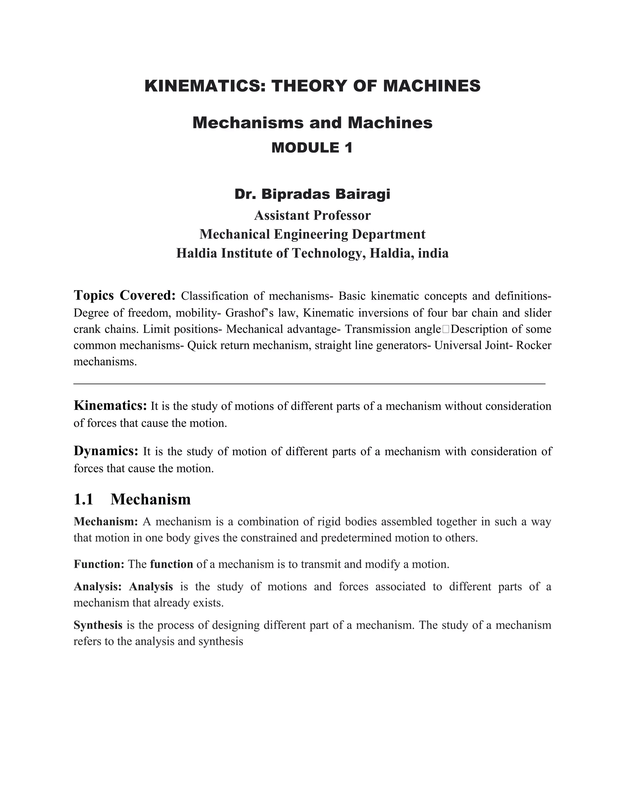
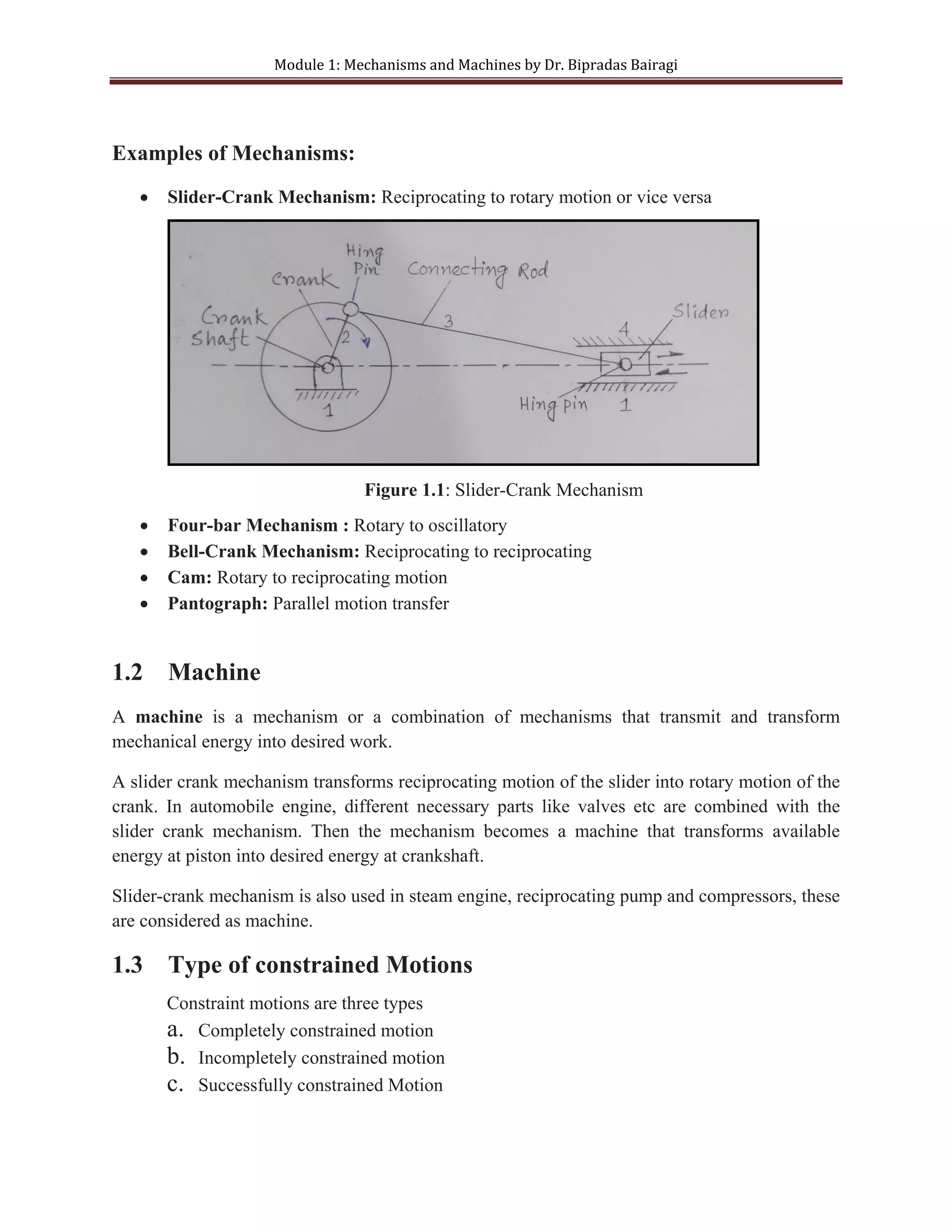
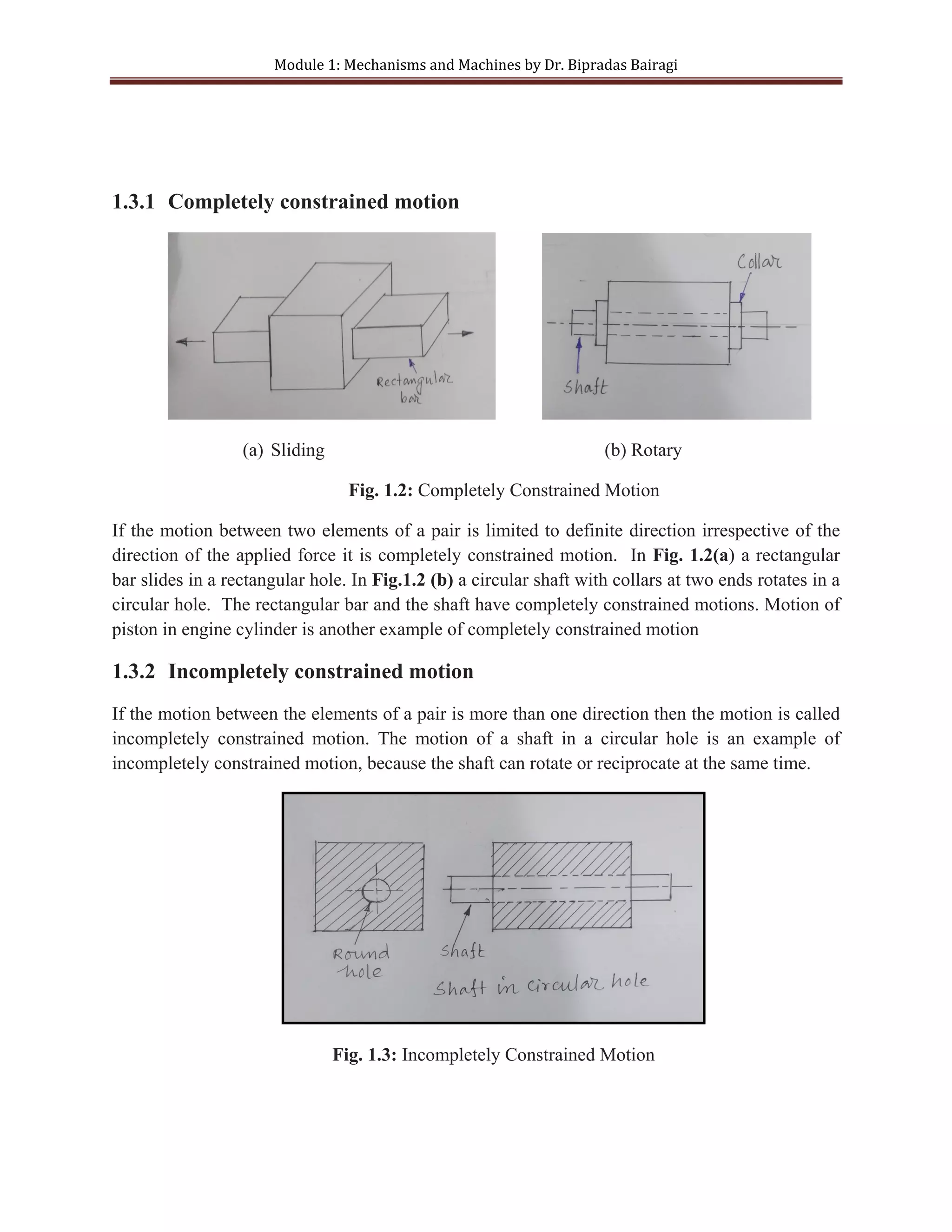
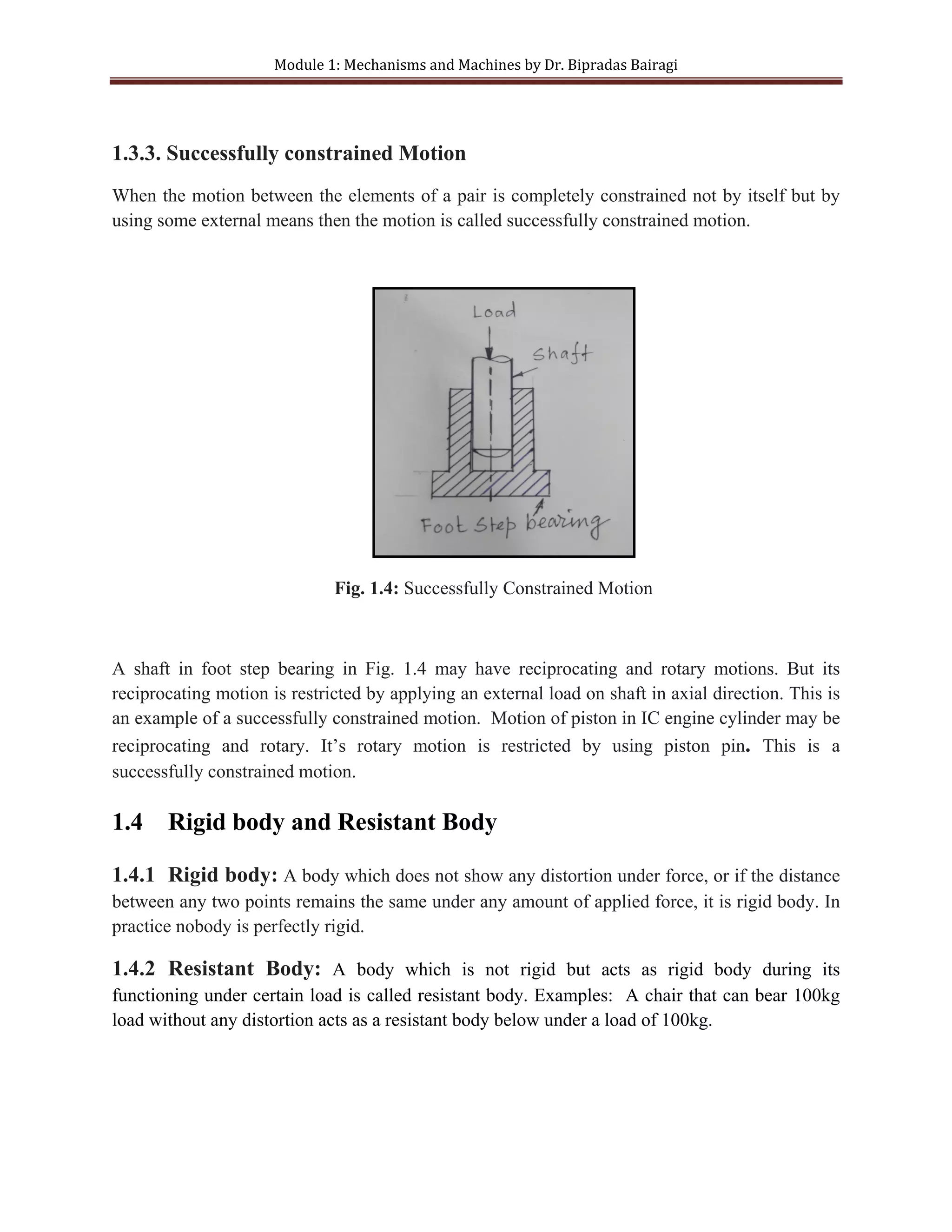
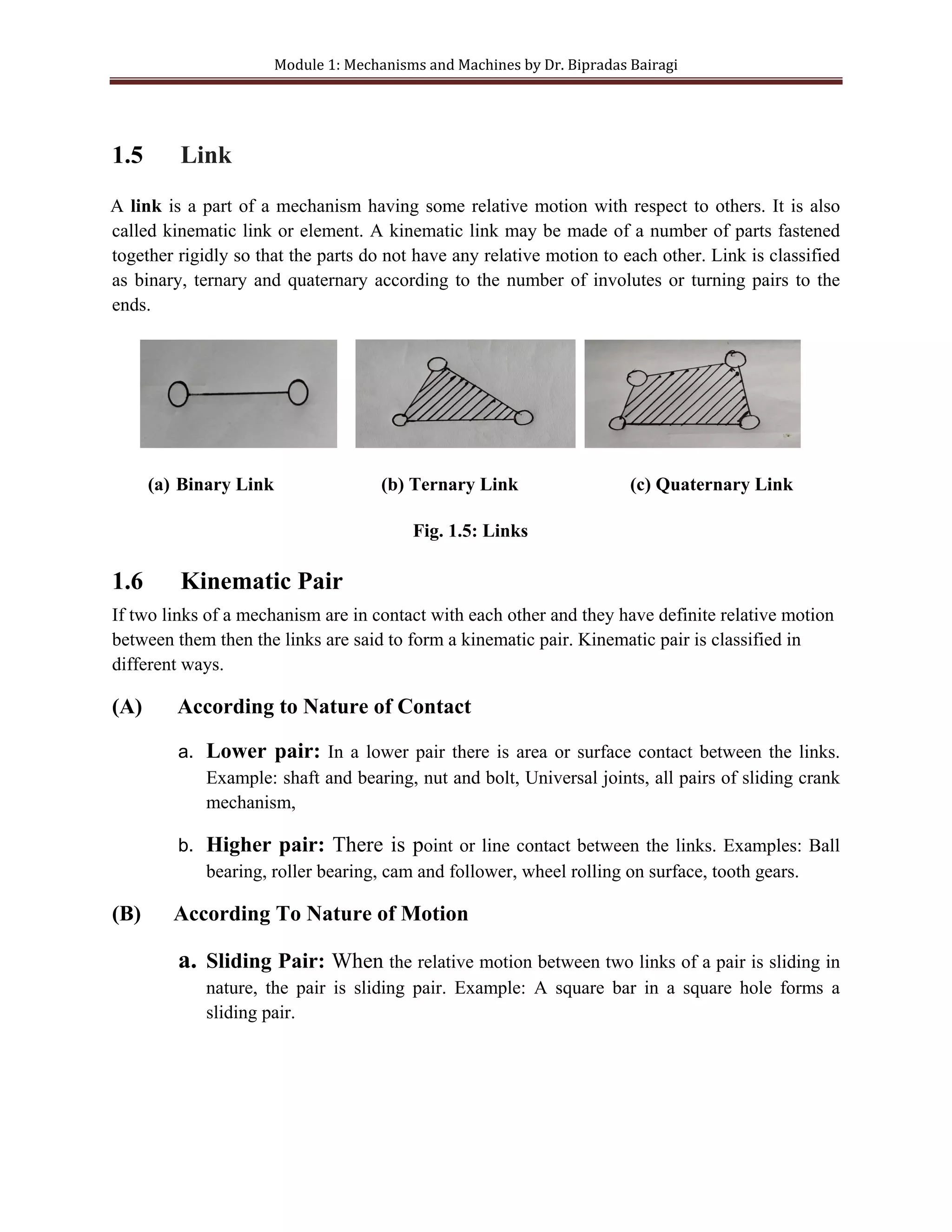
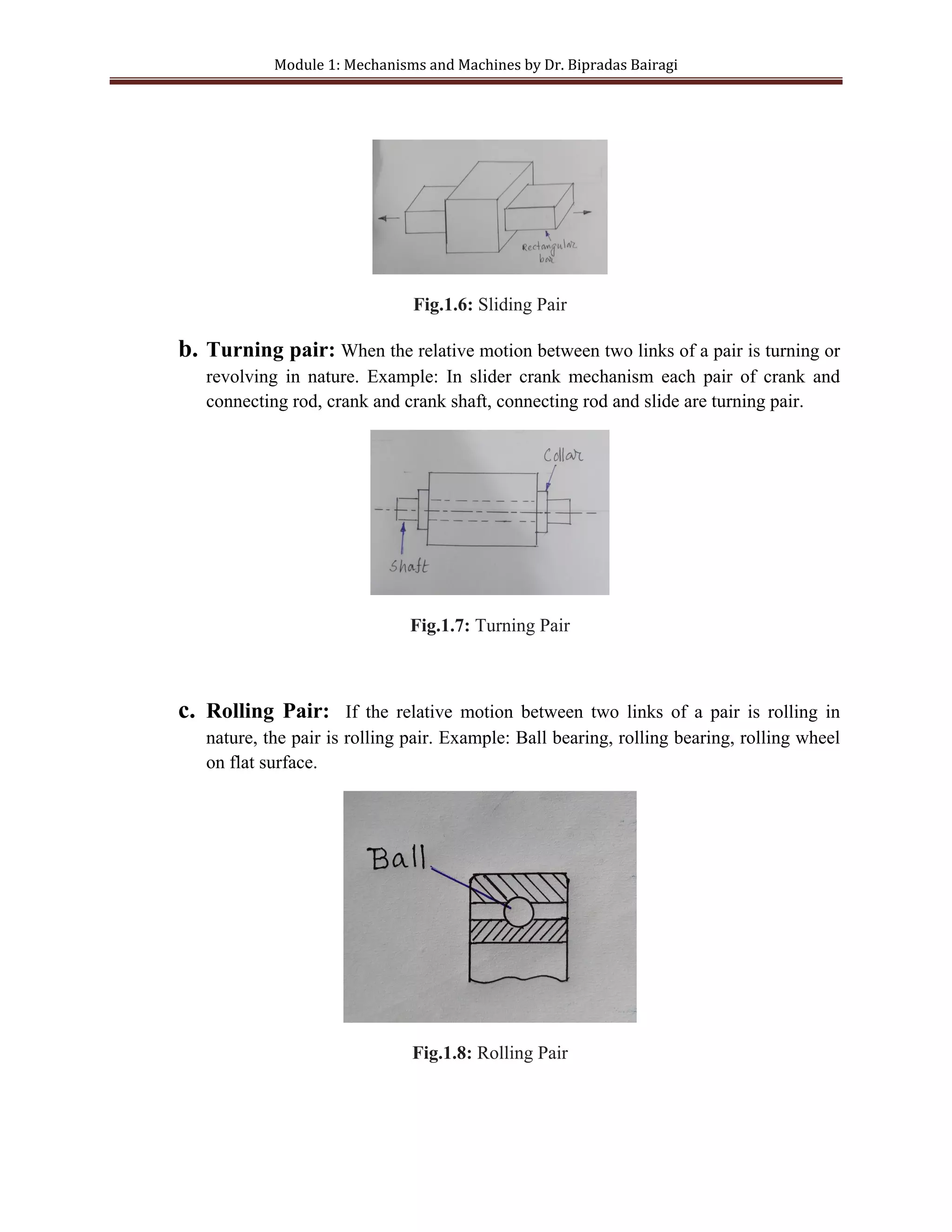
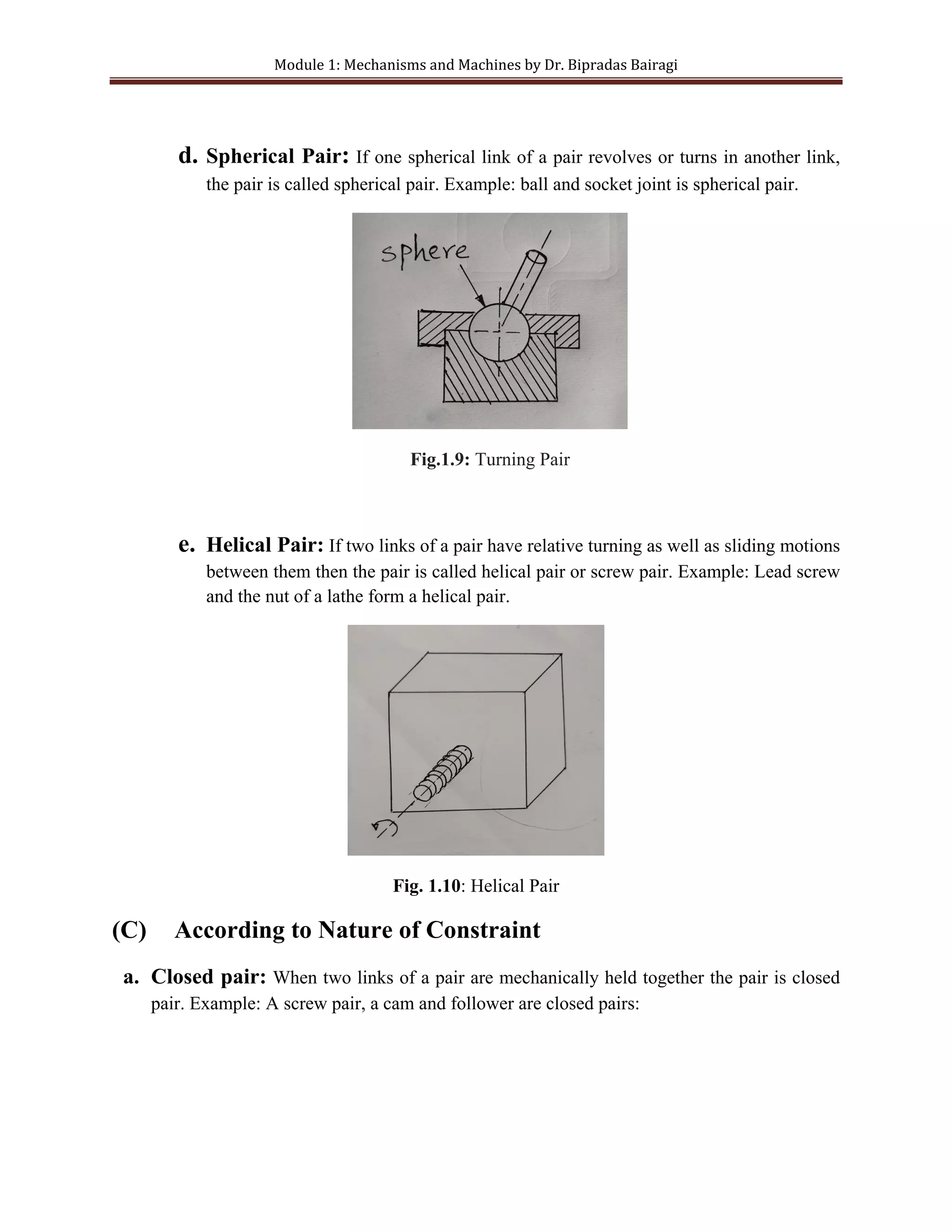
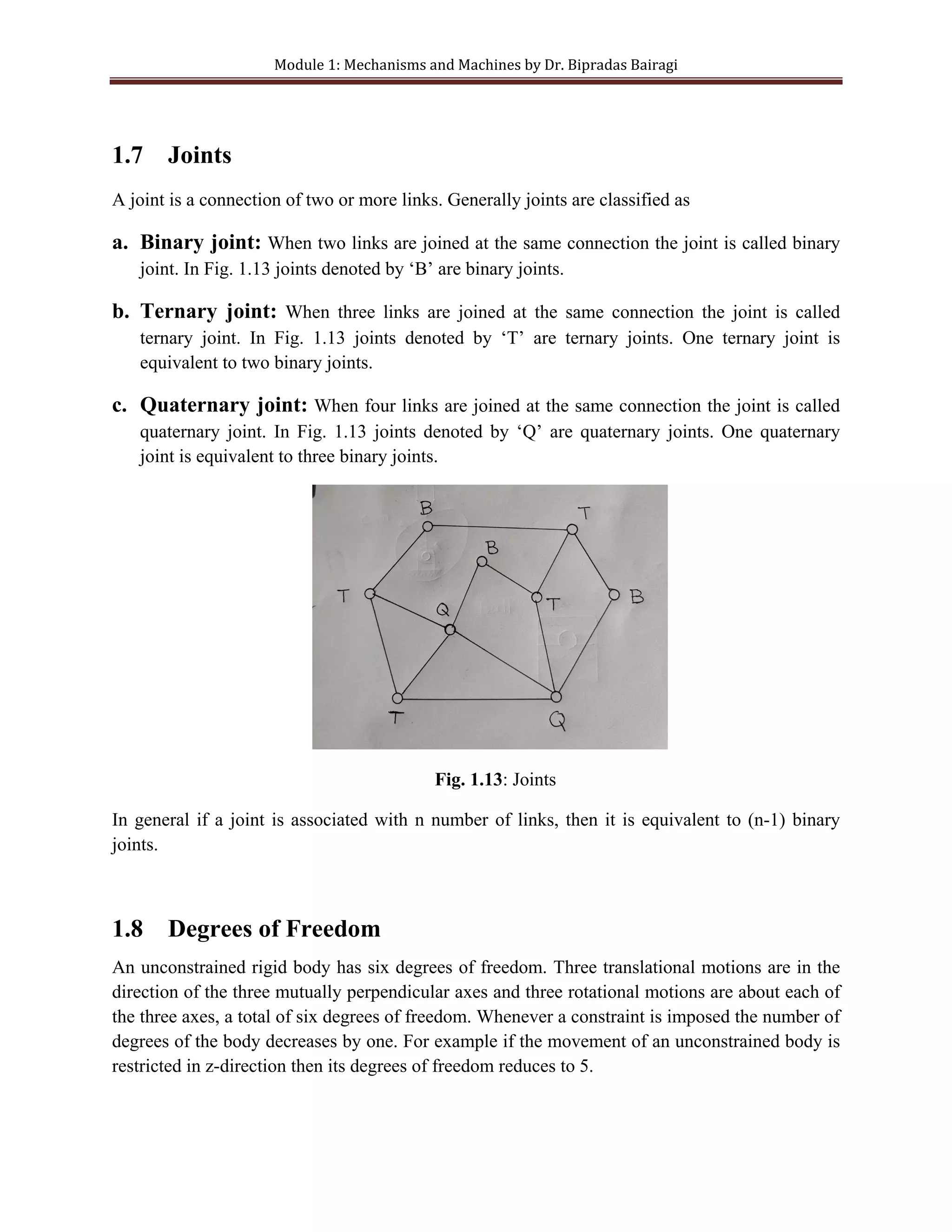
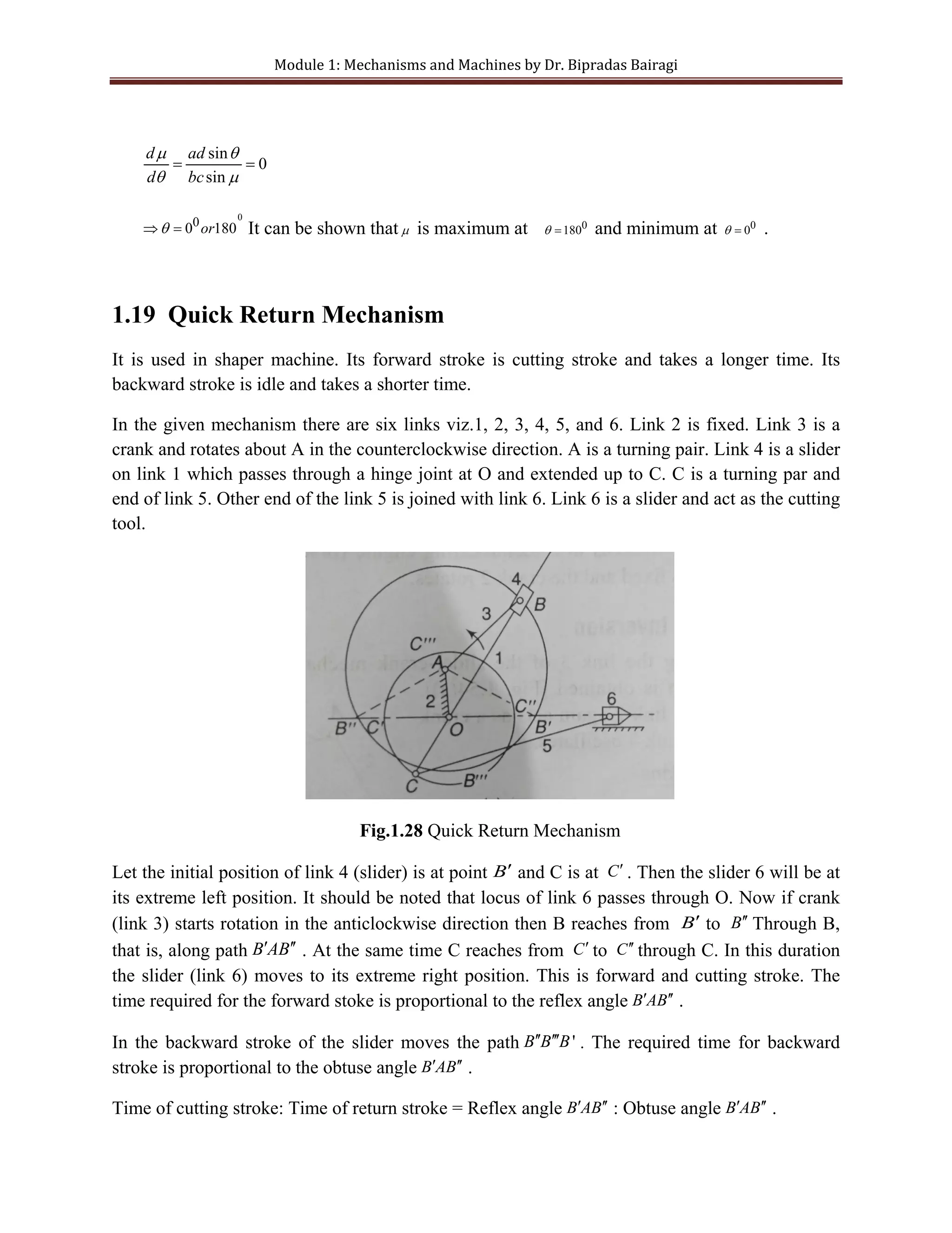
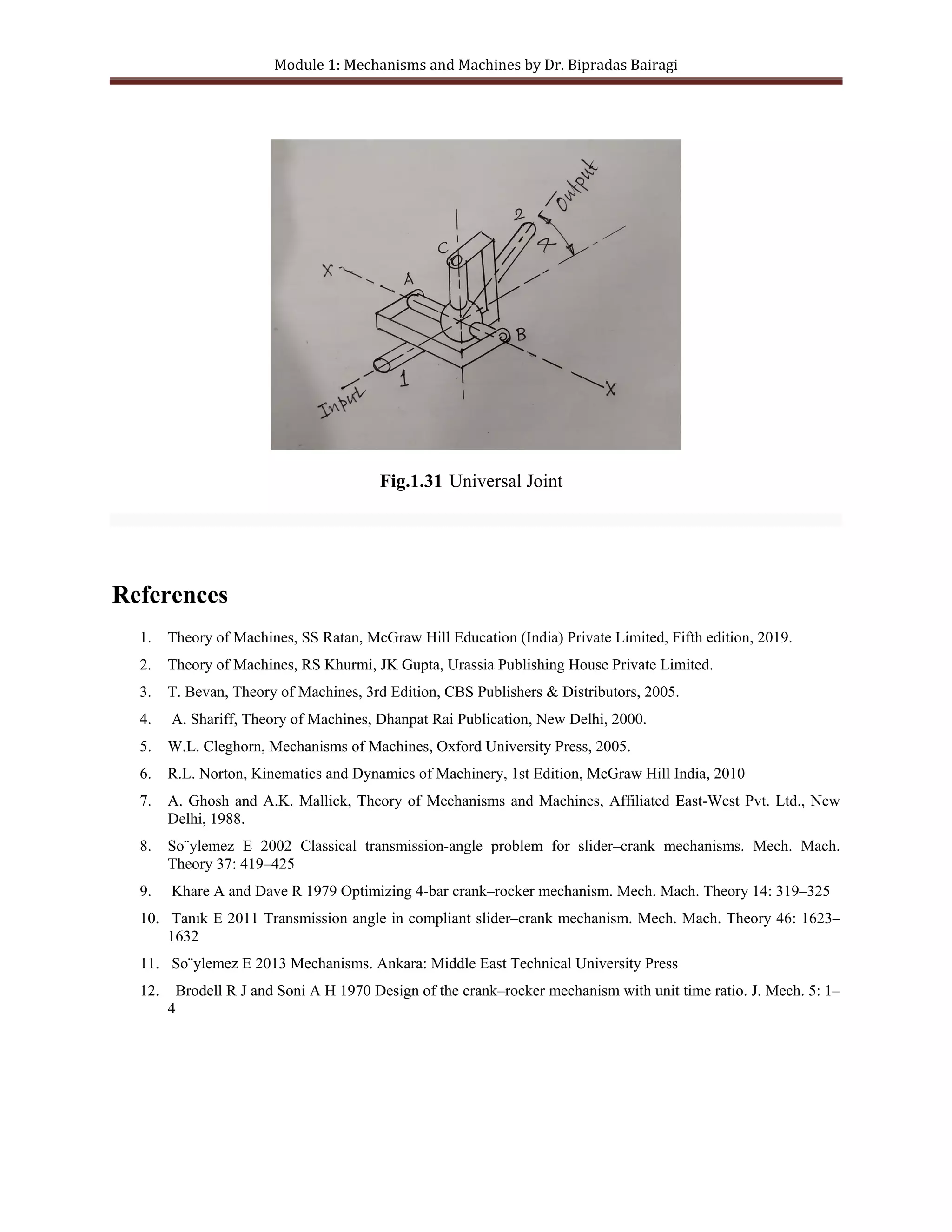
This document provides an overview of kinematics theory and concepts related to mechanisms and machines. It defines key terms like mechanisms, kinematic pairs, degrees of freedom, and mobility. It also describes common mechanisms like the slider-crank and four-bar mechanisms. Examples of constrained motions and different types of links, joints, and chains are explained.
A cam is a rotating machine element which gives reciprocating or oscillating motion to another element known as the follower.Though the cams may be classified in many ways, among them we can classify:
1. Radial or disc cam.
2. Cylindrical cam.
This PPT describes toothed wheels technically called as Gears. It consists of classification of gears that are commonly used in industries. Mostly when any mechanical components came to industrial scenario it deals with dynamic and static characteristics. Metallurgical restriction are also been involved in this .This PPT will definitely clears all the doubts and allow you to think more.
Kinematic link, Types of links, Kinematic pair, Types of constrained motions, Types of Kinematic pairs, Kinematic chain, Types of joints, Mechanism, Machine, Degree of freedom, Mobility of Mechanism, Inversion, Grashoff’s law, Four-Bar Chain and its Inversions, Slider crank Chain and its Inversions, Double slider crank Chain and its Conversions, Mechanisms with Higher pairs, Equivalent Linkages and its Cases - Sliding Pairs in Place of Turning Pairs, Spring in Place of Turning Pairs, Cam Pair in Place of Turning Pairs
Static force analysis, Unit-1 of Dynamics of machines of VTU Syllabus compiled by Hareesha N Gowda, Asst. Prof, Dayananda Sagar College of Engg, Blore. Please write to hareeshang@gmail.com for suggestions and criticisms.
Unit 1-introduction to Mechanisms, Kinematics of machines of VTU Syllabus prepared by Hareesha N Gowda, Asst. Prof, Dayananda Sagar College of Engg, Blore. Please write to hareeshang@gmail.com for suggestions and criticisms.
PRESENTATION ON WORM GEAR FOR DESIGN OF MACHINE ELEMENT 2 BY :
Ranjan Rajkumar, Ranjan Leishangthem and Daihrii Kholi
of mechanical engineering Department, NATIONAL INSTITUTE OF TECHNOLOGY MANIPUR
THEORY OF MACHINES FOR VTU, AMIE, DME STUDENTS..
The study of a mechanism involves its analysis as well as synthesis.
Analysis is the study of motions and forces concerning different parts
of an existing mechanism. Whereas Synthesis involves the design of its
different parts.
Mechanics: It is that branch of scientific analysis which deals with
motion, time and force.
Kinematics is the study of motion, without considering the forces
which produce that motion. Kinematics of machines deals with the
study of the relative motion of machine parts. It involves the study of
position, displacement, velocity and acceleration of machine parts.
Dynamics of machines involves the study of forces acting on the
machine parts and the motions resulting from these forces.
Plane motion: A body has plane motion, if all its points move in
planes which are parallel to some reference plane. A body with plane
motion will have only three degrees of freedom. i.e., linear along two
axes parallel to the reference plane and rotational/angular about the
axis perpendicular to the reference plane. (eg. linear along X and Z
and rotational about Y.)The reference plane is called plane of motion.
Plane motion can be of three types. 1) Translation 2) rotation and 3)
combination of translation and rotation.
Translation: A body has translation if it moves so that all straight
lines in the body move to parallel positions. Rectilinear translation is a
motion wherein all points of the body move in straight lie paths.
Eg. The slider in slider crank mechanism has rectilinear translation.
Vehicle kinematics and dynamics (vkd) short answer for gtuKamil Saiyed
imp short answers for GTU exams. its for automobile engineering students english medium. we know many of the book are not available and we are looking for imp's and shortcuts to pass the exam easily
NO1 Uk best vashikaran specialist in delhi vashikaran baba near me online vas...Amil Baba Dawood bangali
Contact with Dawood Bhai Just call on +92322-6382012 and we'll help you. We'll solve all your problems within 12 to 24 hours and with 101% guarantee and with astrology systematic. If you want to take any personal or professional advice then also you can call us on +92322-6382012 , ONLINE LOVE PROBLEM & Other all types of Daily Life Problem's.Then CALL or WHATSAPP us on +92322-6382012 and Get all these problems solutions here by Amil Baba DAWOOD BANGALI
#vashikaranspecialist #astrologer #palmistry #amliyaat #taweez #manpasandshadi #horoscope #spiritual #lovelife #lovespell #marriagespell#aamilbabainpakistan #amilbabainkarachi #powerfullblackmagicspell #kalajadumantarspecialist #realamilbaba #AmilbabainPakistan #astrologerincanada #astrologerindubai #lovespellsmaster #kalajaduspecialist #lovespellsthatwork #aamilbabainlahore#blackmagicformarriage #aamilbaba #kalajadu #kalailam #taweez #wazifaexpert #jadumantar #vashikaranspecialist #astrologer #palmistry #amliyaat #taweez #manpasandshadi #horoscope #spiritual #lovelife #lovespell #marriagespell#aamilbabainpakistan #amilbabainkarachi #powerfullblackmagicspell #kalajadumantarspecialist #realamilbaba #AmilbabainPakistan #astrologerincanada #astrologerindubai #lovespellsmaster #kalajaduspecialist #lovespellsthatwork #aamilbabainlahore #blackmagicforlove #blackmagicformarriage #aamilbaba #kalajadu #kalailam #taweez #wazifaexpert #jadumantar #vashikaranspecialist #astrologer #palmistry #amliyaat #taweez #manpasandshadi #horoscope #spiritual #lovelife #lovespell #marriagespell#aamilbabainpakistan #amilbabainkarachi #powerfullblackmagicspell #kalajadumantarspecialist #realamilbaba #AmilbabainPakistan #astrologerincanada #astrologerindubai #lovespellsmaster #kalajaduspecialist #lovespellsthatwork #aamilbabainlahore #Amilbabainuk #amilbabainspain #amilbabaindubai #Amilbabainnorway #amilbabainkrachi #amilbabainlahore #amilbabaingujranwalan #amilbabainislamabad
Cosmetic shop management system project report.pdfKamal Acharya
Buying new cosmetic products is difficult. It can even be scary for those who have sensitive skin and are prone to skin trouble. The information needed to alleviate this problem is on the back of each product, but it's thought to interpret those ingredient lists unless you have a background in chemistry.
Instead of buying and hoping for the best, we can use data science to help us predict which products may be good fits for us. It includes various function programs to do the above mentioned tasks.
Data file handling has been effectively used in the program.
The automated cosmetic shop management system should deal with the automation of general workflow and administration process of the shop. The main processes of the system focus on customer's request where the system is able to search the most appropriate products and deliver it to the customers. It should help the employees to quickly identify the list of cosmetic product that have reached the minimum quantity and also keep a track of expired date for each cosmetic product. It should help the employees to find the rack number in which the product is placed.It is also Faster and more efficient way.
Final project report on grocery store management system..pdfKamal Acharya
In today’s fast-changing business environment, it’s extremely important to be able to respond to client needs in the most effective and timely manner. If your customers wish to see your business online and have instant access to your products or services.
Online Grocery Store is an e-commerce website, which retails various grocery products. This project allows viewing various products available enables registered users to purchase desired products instantly using Paytm, UPI payment processor (Instant Pay) and also can place order by using Cash on Delivery (Pay Later) option. This project provides an easy access to Administrators and Managers to view orders placed using Pay Later and Instant Pay options.
In order to develop an e-commerce website, a number of Technologies must be studied and understood. These include multi-tiered architecture, server and client-side scripting techniques, implementation technologies, programming language (such as PHP, HTML, CSS, JavaScript) and MySQL relational databases. This is a project with the objective to develop a basic website where a consumer is provided with a shopping cart website and also to know about the technologies used to develop such a website.
This document will discuss each of the underlying technologies to create and implement an e- commerce website.
Student information management system project report ii.pdfKamal Acharya
Our project explains about the student management. This project mainly explains the various actions related to student details. This project shows some ease in adding, editing and deleting the student details. It also provides a less time consuming process for viewing, adding, editing and deleting the marks of the students.
CW RADAR, FMCW RADAR, FMCW ALTIMETER, AND THEIR PARAMETERSveerababupersonal22
It consists of cw radar and fmcw radar ,range measurement,if amplifier and fmcw altimeterThe CW radar operates using continuous wave transmission, while the FMCW radar employs frequency-modulated continuous wave technology. Range measurement is a crucial aspect of radar systems, providing information about the distance to a target. The IF amplifier plays a key role in signal processing, amplifying intermediate frequency signals for further analysis. The FMCW altimeter utilizes frequency-modulated continuous wave technology to accurately measure altitude above a reference point.
Using recycled concrete aggregates (RCA) for pavements is crucial to achieving sustainability. Implementing RCA for new pavement can minimize carbon footprint, conserve natural resources, reduce harmful emissions, and lower life cycle costs. Compared to natural aggregate (NA), RCA pavement has fewer comprehensive studies and sustainability assessments.
1. KINEMATICS: THEORY OF MACHINES
Mechanisms and Machines
MODULE 1
Dr. Bipradas Bairagi
Assistant Professor
Mechanical Engineering Department
Haldia Institute of Technology, Haldia, india
Topics Covered: Classification of mechanisms- Basic kinematic concepts and definitions-
Degree of freedom, mobility- Grashof’s law, Kinematic inversions of four bar chain and slider
crank chains. Limit positions- Mechanical advantage- Transmission angleDescription of some
common mechanisms- Quick return mechanism, straight line generators- Universal Joint- Rocker
mechanisms.
_____________________________________________________________________________
Kinematics: It is the study of motions of different parts of a mechanism without consideration
of forces that cause the motion.
Dynamics: It is the study of motion of different parts of a mechanism with consideration of
forces that cause the motion.
1.1 Mechanism
Mechanism: A mechanism is a combination of rigid bodies assembled together in such a way
that motion in one body gives the constrained and predetermined motion to others.
Function: The function of a mechanism is to transmit and modify a motion.
Analysis: Analysis is the study of motions and forces associated to different parts of a
mechanism that already exists.
Synthesis is the process of designing different part of a mechanism. The study of a mechanism
refers to the analysis and synthesis
2. Module 1: Mechanisms and Machines by Dr. Bipradas Bairagi
Examples of Mechanisms:
• Slider-Crank Mechanism: Reciprocating to rotary motion or vice versa
Figure 1.1: Slider-Crank Mechanism
• Four-bar Mechanism : Rotary to oscillatory
• Bell-Crank Mechanism: Reciprocating to reciprocating
• Cam: Rotary to reciprocating motion
• Pantograph: Parallel motion transfer
1.2 Machine
A machine is a mechanism or a combination of mechanisms that transmit and transform
mechanical energy into desired work.
A slider crank mechanism transforms reciprocating motion of the slider into rotary motion of the
crank. In automobile engine, different necessary parts like valves etc are combined with the
slider crank mechanism. Then the mechanism becomes a machine that transforms available
energy at piston into desired energy at crankshaft.
Slider-crank mechanism is also used in steam engine, reciprocating pump and compressors, these
are considered as machine.
1.3 Type of constrained Motions
Constraint motions are three types
a. Completely constrained motion
b. Incompletely constrained motion
c. Successfully constrained Motion
3. Module 1: Mechanisms and Machines by Dr. Bipradas Bairagi
1.3.1 Completely constrained motion
(a) Sliding (b) Rotary
Fig. 1.2: Completely Constrained Motion
If the motion between two elements of a pair is limited to definite direction irrespective of the
direction of the applied force it is completely constrained motion. In Fig. 1.2(a) a rectangular
bar slides in a rectangular hole. In Fig.1.2 (b) a circular shaft with collars at two ends rotates in a
circular hole. The rectangular bar and the shaft have completely constrained motions. Motion of
piston in engine cylinder is another example of completely constrained motion
1.3.2 Incompletely constrained motion
If the motion between the elements of a pair is more than one direction then the motion is called
incompletely constrained motion. The motion of a shaft in a circular hole is an example of
incompletely constrained motion, because the shaft can rotate or reciprocate at the same time.
Fig. 1.3: Incompletely Constrained Motion
4. Module 1: Mechanisms and Machines by Dr. Bipradas Bairagi
1.3.3. Successfully constrained Motion
When the motion between the elements of a pair is completely constrained not by itself but by
using some external means then the motion is called successfully constrained motion.
Fig. 1.4: Successfully Constrained Motion
A shaft in foot step bearing in Fig. 1.4 may have reciprocating and rotary motions. But its
reciprocating motion is restricted by applying an external load on shaft in axial direction. This is
an example of a successfully constrained motion. Motion of piston in IC engine cylinder may be
reciprocating and rotary. It’s rotary motion is restricted by using piston pin. This is a
successfully constrained motion.
1.4 Rigid body and Resistant Body
1.4.1 Rigid body: A body which does not show any distortion under force, or if the distance
between any two points remains the same under any amount of applied force, it is rigid body. In
practice nobody is perfectly rigid.
1.4.2 Resistant Body: A body which is not rigid but acts as rigid body during its
functioning under certain load is called resistant body. Examples: A chair that can bear 100kg
load without any distortion acts as a resistant body below under a load of 100kg.
5. Module 1: Mechanisms and Machines by Dr. Bipradas Bairagi
1.5 Link
A link is a part of a mechanism having some relative motion with respect to others. It is also
called kinematic link or element. A kinematic link may be made of a number of parts fastened
together rigidly so that the parts do not have any relative motion to each other. Link is classified
as binary, ternary and quaternary according to the number of involutes or turning pairs to the
ends.
(a) Binary Link (b) Ternary Link (c) Quaternary Link
Fig. 1.5: Links
1.6 Kinematic Pair
If two links of a mechanism are in contact with each other and they have definite relative motion
between them then the links are said to form a kinematic pair. Kinematic pair is classified in
different ways.
(A) According to Nature of Contact
a. Lower pair: In a lower pair there is area or surface contact between the links.
Example: shaft and bearing, nut and bolt, Universal joints, all pairs of sliding crank
mechanism,
b. Higher pair: There is point or line contact between the links. Examples: Ball
bearing, roller bearing, cam and follower, wheel rolling on surface, tooth gears.
(B) According To Nature of Motion
a. Sliding Pair: When the relative motion between two links of a pair is sliding in
nature, the pair is sliding pair. Example: A square bar in a square hole forms a
sliding pair.
6. Module 1: Mechanisms and Machines by Dr. Bipradas Bairagi
Fig.1.6: Sliding Pair
b. Turning pair: When the relative motion between two links of a pair is turning or
revolving in nature. Example: In slider crank mechanism each pair of crank and
connecting rod, crank and crank shaft, connecting rod and slide are turning pair.
Fig.1.7: Turning Pair
c. Rolling Pair: If the relative motion between two links of a pair is rolling in
nature, the pair is rolling pair. Example: Ball bearing, rolling bearing, rolling wheel
on flat surface.
Fig.1.8: Rolling Pair
7. Module 1: Mechanisms and Machines by Dr. Bipradas Bairagi
d. Spherical Pair: If one spherical link of a pair revolves or turns in another link,
the pair is called spherical pair. Example: ball and socket joint is spherical pair.
Fig.1.9: Turning Pair
e. Helical Pair: If two links of a pair have relative turning as well as sliding motions
between them then the pair is called helical pair or screw pair. Example: Lead screw
and the nut of a lathe form a helical pair.
Fig. 1.10: Helical Pair
(C) According to Nature of Constraint
a. Closed pair: When two links of a pair are mechanically held together the pair is closed
pair. Example: A screw pair, a cam and follower are closed pairs:
8. Module 1: Mechanisms and Machines by Dr. Bipradas Bairagi
Fig. 1.11: Closed Pair
b. Unclosed Pair: If the links of a pair are in contact to each other due to action of some
spring or gravitational force the pair is unclosed pair. Example: In cam and follower pair,
follower remains in contact of cam due to gravitational force, therefore it is unclosed pair.
Fig. 1.12: Unclosed Pair
9. Module 1: Mechanisms and Machines by Dr. Bipradas Bairagi
1.7 Joints
A joint is a connection of two or more links. Generally joints are classified as
a. Binary joint: When two links are joined at the same connection the joint is called binary
joint. In Fig. 1.13 joints denoted by ‘B’ are binary joints.
b. Ternary joint: When three links are joined at the same connection the joint is called
ternary joint. In Fig. 1.13 joints denoted by ‘T’ are ternary joints. One ternary joint is
equivalent to two binary joints.
c. Quaternary joint: When four links are joined at the same connection the joint is called
quaternary joint. In Fig. 1.13 joints denoted by ‘Q’ are quaternary joints. One quaternary
joint is equivalent to three binary joints.
Fig. 1.13: Joints
In general if a joint is associated with n number of links, then it is equivalent to (n-1) binary
joints.
1.8 Degrees of Freedom
An unconstrained rigid body has six degrees of freedom. Three translational motions are in the
direction of the three mutually perpendicular axes and three rotational motions are about each of
the three axes, a total of six degrees of freedom. Whenever a constraint is imposed the number of
degrees of the body decreases by one. For example if the movement of an unconstrained body is
restricted in z-direction then its degrees of freedom reduces to 5.
10. Module 1: Mechanisms and Machines by Dr. Bipradas Bairagi
1.9 Kinematic Chain
A Kinematic chain is an assembly of links in which definite relative motion between the links is
possible.
Non-Kinematic Chain: If motion in one chain produces indefinite motion to other links
then the chain is called non-kinematic chain.
Redundant kinematic chain: If there is no relative motion between the links of a chain it is
redundant kinematic chain.
1.10 Linkage and Structure
Linkage: A linkage is a kinematic chain with one link fixed at the ground.
Structure or Locked System: If one of the links of a redundant chain is fixed, then the
chain is called structure or locked system. The degree of freedom of a structure or locked system
is zero.
Super-Structure: A structure with negative degree of freedom is called super-structure.
1.11 Mobility of Mechanism
The mobility of a mechanism is its degrees of freedom. Degrees of freedom a mechanism is
defined as the number of inputs required to have a constrained motion of other links. The number
of degrees of freedom of a mechanism is measured in terms of the number of links, number of
pairs with type.
Let
N = Total number of links in a mechanism (including the frame)
P1 = Number of pairs having 1degree of freedom
P2 = Number of pairs having 2 degrees of freedom
P3 = Number of pairs having 3 degrees of freedom
P4 = Number of pairs having 4 degrees of freedom
P5 = Number of pairs having 5 degrees of freedom
F= Degrees of freedom of the mechanism
11. Module 1: Mechanisms and Machines by Dr. Bipradas Bairagi
Therefore,
N -1= Number of movable links (Since one link in every mechanism is fixed)
6(N -1) = degrees of freedom of (N -1) links
5P1= Reduction of degrees of freedom of P1 pairs with one degree of freedom
4P2 = Reduction of degrees of freedom of P2 pairs with two degree of freedom
3P3 = Reduction of degrees of freedom of P3 pairs with two degree of freedom
2P4 = Reduction of degrees of freedom of P4 pairs with two degree of freedom
P5 = Reduction of degrees of freedom of P5 pairs with two degree of freedom
Degrees of freedom of a mechanism in space can be expressed as
F = 6 (N-1) - 5P1 – 4P2 - 3P3 - 2P4 - P5
Degrees of freedom of a mechanism in a plane (two dimensions) can be expressed as
F = 3 (N-1) - 2P1 –P2
The above equation is called Grubler’s Criterion.
If a linkage has pairs with one degree of freedom only, the above equation reduces to
F = 3 (N-1) - 2P1
It is known as Kutzbach’s Criterion.
1.12 Kinematic Inversions of Four Bar Chain
A four-bar link consists of four rigid links connected as a quadrilateral by four pin joints. If one
link of the chain is fixed then it is called a mechanism or linkage. A link that makes complete
revolution is called crank, the link opposite to the crank is called coupler, and if the fourth link
oscillates it is called rocker, but if it makes complete revolutions then it is also called a second
crank.
12. Module 1: Mechanisms and Machines by Dr. Bipradas Bairagi
Fig. 1.14 Four bar Mechanism
Inversion of four bar mechanism is obtained by fixing different links one at a time.
Class-I Four Bar Mechanism
If the sum of lengths of the shortest and the longest bars is less than the sum of the lengths of the
other two bars then it is called a class-I four bar mechanism .Let, in a Class-I four bar mechanism
d is the shortest links, b is opposite to d, where a and c are adjacent to the link d, then
(a) If a or c is fixed, d can make complete revolution, b oscillates. That is if any links
adjacent to the shortest link is fixed, then the shortest link makes complete revolution,
the link opposite to shortest link oscillates. Then the mechanism is called crank-rocker,
crank- oscillating converter or crank-lever mechanism.
Fig. 1.15: Crank- Rocker Mechanism
(b) If b is fixed, then both a and c oscillate. In other words, if in class–I four bar mechanism,
the bar opposite to the shortest bar is fixed then both the adjacent bars will oscillate. This
13. Module 1: Mechanisms and Machines by Dr. Bipradas Bairagi
mechanism is called rocker-rocker, double-rocker, double-lever or oscillating-oscillating
mechanism.
Fig. 1.16: Double Rocker Mechanism
Grashof’s Law: It states that a four-bar mechanism has at least one crank if the sum of the
length of shortest link and the longest link is less than the sum of the length of the other two
Links.
Class II Four Bar Mechanism: If the sum of lengths of the shortest and the longest bars is
more than the sum of the lengths of the other two bars then the mechanism is called a class-II
four bar mechanism.
In this case, fixation of any link (inversion mechanism) will result double rocker mechanism.
The links adjacent to the fixed link oscillate.
1.13 Parallel-Crank Four Bar Linkage
If in a four-bar mechanism, the opposite links are equal in length and if any of the four links are
fixed the adjacent links will have a revolving motion, and these two adjacent links act as cranks.
Fig. 1.17: Parallel-Crank Four-Bar Mechanism
14. Module 1: Mechanisms and Machines by Dr. Bipradas Bairagi
1.14 Deltoid Linkage
In this case, each two equal links are adjacent; one of the shortest links is fixed, for each
revolution of the longest link the other shortest link will revolve twice. Here, AD=AB, and
BC=CD.
Fig. 1.18 Deltoid Mechanism
1.15 Kinematic Inversions of Slider Crank Chains.
A single slider crank chain is obtained by replacing one turning pair with a sliding pair of a four-
bar chain. A double slider crank chain can be obtained by replacing two turning pairs with two
sliding pairs of a four-bar chain. Different mechanisms obtained by fixing different links are
called inversion of the original mechanism. The inversion of the slider-crank mechanisms are as
follows:
(a)First Inversion: The first inversion of slider crank mechanism is obtained by fixing
link 1, making link 2 to revolve and making link 4 to slide. The slider crank mechanism
of first inversion is used in reciprocating engine and reciprocating compressor.
15. Module 1: Mechanisms and Machines by Dr. Bipradas Bairagi
Fig. 1.19: First Inversion of Slider-Crank Mechanism
(b) Second Inversion: Second inversion of slider-crank mechanisms can be obtained if
link 2 is fixed instead of link 1. The second inversion of slider crank mechanism is used
in Whitworth quick-return mechanism and rotary engine.
Fig. 1.20 Second Inversion of Slider-Crank Mechanism
(c) Third Inversion: The third inversion of slider crank mechanism is obtained by fixing
link 3. Link 2 revolves and link 4 oscillates. It is used in oscillating cylinder engine as
well as crank and slotted lever mechanism.
16. Module 1: Mechanisms and Machines by Dr. Bipradas Bairagi
Fig. 1.21 Third Inversion of Slider-Crank Mechanism
(d)Fourth Inversion: The fourth inversion of slider crank mechanism is obtained by
fixing link 4 (Fig. 1.22). Link 3 oscillates about the fixed pivot B on link 4. It is applied
in hand pump.
Fig. 1.22 Fourth Inversion of Slider-Crank Mechanism
1.16 Double Slider-Crank Chain
A four bar mechanism with two turning pair and two sliding pair such that the two turning pairs
are adjacent and the sliding pairs are also adjacent is called double sliding-pair mechanism.
Inversions of the mechanisms are as follows.
(a)First Inversion: It is obtained when link1 is fixed; two adjacent pairs connecting
links 2 with 3 and link 3 with 4 are turning pair. Remaining two adjacent pairs are
sliding pairs (Fig. 1.23). Example: Elliptical trammel.
17. Module 1: Mechanisms and Machines by Dr. Bipradas Bairagi
Fig.1.23 First Inversion of Double-Slider-Crank Chain
(b) Second Inversion: Second inversion is obtained when any one of the sliding
block of the first inversion is fixed. If link 4 is fixed then link 3 oscillates about A and
the link reciprocates horizontally (Fig. 1.24).
Fig.1.24 Second Inversion of Double-Slider-Crank Chain
(c) Third Inversion: Third inversion is obtained when link 3 of first inversion is
fixed and link 1 can freely move. Example of third inversion is Oldham’s coupling.
18. Module 1: Mechanisms and Machines by Dr. Bipradas Bairagi
Fig.1.25 Third Inversion of Double-Slider-Crank Chain
1.17 Mechanical advantage
Mechanical advantage of a mechanism is defined as the ratio of output force or output torque to
the input force to input torque. Let the input torque and corresponding angular speed in link 2 is
T2 and w2 respectively (Fig.1.26). The output torque and corresponding angular speed in link 4 is
T4 and w4 respectively. If inertia force and the frictional loss can be ignored then,
Fig .1.26 Mechanical Advantage
Input power = Output power
2 2 4 4
T w T w
=
19. Module 1: Mechanisms and Machines by Dr. Bipradas Bairagi
4 2
2 4
T w
MA
T w
= =
Mechanical advantage of a mechanism is given by the ratio of output torque to input torque=
reciprocal of the angular velocity ratio.
1.18 Transmission angle
In the four bar mechanism link AD fixed, link BC is coupler, AB is input link CD is output link.
The angle µ between input link and output link is called Transmission Angle. Torque from
input link BC to output link CD is transmitted through coupler BC. Transmission of torque is
maximum if
0
90
µ = and minimum if 0
0
µ = .
Fig. 1.27 Transmission Angle
From triangle ABD and BCD, using cosine formula
2 2 2
2 2 2
2 cos
2 cos
a d ad l
b c bc l
θ
µ
+ − =
+ − =
Equating the above equation we get,
2 2 2 2
2 cos 2 cos 0
a d b c ad bc
θ µ
+ − − − + =
Differentiating with respect to θ
2 sin 2 sin 0
d
ad bc
d
µ
θ µ
θ
− =
and equating
d
d
µ
θ to zero we get
20. Module 1: Mechanisms and Machines by Dr. Bipradas Bairagi
sin
0
sin
d ad
d bc
µ θ
θ µ
= =
0
0
0 180
or
θ
⇒ = It can be shown that µ is maximum at 0
180
θ = and minimum at 0
0
θ = .
1.19 Quick Return Mechanism
It is used in shaper machine. Its forward stroke is cutting stroke and takes a longer time. Its
backward stroke is idle and takes a shorter time.
In the given mechanism there are six links viz.1, 2, 3, 4, 5, and 6. Link 2 is fixed. Link 3 is a
crank and rotates about A in the counterclockwise direction. A is a turning pair. Link 4 is a slider
on link 1 which passes through a hinge joint at O and extended up to C. C is a turning par and
end of link 5. Other end of the link 5 is joined with link 6. Link 6 is a slider and act as the cutting
tool.
Fig.1.28 Quick Return Mechanism
Let the initial position of link 4 (slider) is at point B′ and C is at C′ . Then the slider 6 will be at
its extreme left position. It should be noted that locus of link 6 passes through O. Now if crank
(link 3) starts rotation in the anticlockwise direction then B reaches from B′ to B′′ Through B,
that is, along path B AB
′ ′′ . At the same time C reaches from C′ to C′′ through C. In this duration
the slider (link 6) moves to its extreme right position. This is forward and cutting stroke. The
time required for the forward stoke is proportional to the reflex angle B AB
′ ′′ .
In the backward stroke of the slider moves the path '
B B B
′′ ′′′ . The required time for backward
stroke is proportional to the obtuse angle B AB
′ ′′ .
Time of cutting stroke: Time of return stroke = Reflex angle B AB
′ ′′ : Obtuse angle B AB
′ ′′ .
21. Module 1: Mechanisms and Machines by Dr. Bipradas Bairagi
1.20 Straight Line Generator
Condition for Exact Straight Line Generation
Let the point B moves along a circle with center O and radius OA=OD. C is a point on the
extension of AB. The point C will moves along a straight line perpendicular to line AO if the
product of length of AB and AC is constant.
Fig.1.29 Condition for Exact Straight Line Generation
Proof. ABD
∆ and AEC
∆ are similar triangles
Therefore,
AD AB
AC AE
=
AB AC
AE
AD
×
=
Since AD is the diameter of the circular path therefore constants. Hence AE is constant if AB
x AC is constant.
Peaucellier Exact Straight Line Motion Mechanism
In this mechanism AB= AE. AB is fixed link. AE is input link and C moves along a circular
path about A, whereas BC=BD, and EC=ED=PC=PD. The point P moves along an exact
straight line perpendicular to extension of BA.
To prove that BE and EP lie on same straight line.
Triangles BCD, ECD and PCD are all isosceles triangle with common base CD. Therefore B,
E and P are on the perpendicular bisector of CD. Hence BE and EP lie on same straight line.
22. Module 1: Mechanisms and Machines by Dr. Bipradas Bairagi
Fig.1.30 Straight Line Generator
To prove the product of the length of BE and BP constant
From triangle BFC, BC2
= BF2
+ CF2
From triangle CFP, CP2
= FP2
+ CF2
BC2
– CP2
= BF2
– FP2
= (BF – FP) (BF + FP)
= BE x BP
Now length of BC and CP are fixed, therefore BE x BP is constant. Thus condition of exact
straight line motion is satisfied. Therefore P moves along an exact straight line.
1.21 Universal Joint
A universal joint or coupling (also known as Hook’s Joint) is used to connect rigid rods with
intersecting axis. It is usually used in shafts with misalignment to transmit rotary motion. It is
used in automobile to transmit power to rear axis. When this joint connects two shafts, driving
shaft rotates uniformly and driven shaft rotates at variable speed. Universal joint consists of a
pair of hinges joints at 90 degree orientation.
23. Module 1: Mechanisms and Machines by Dr. Bipradas Bairagi
Fig.1.31 Universal Joint
References
1. Theory of Machines, SS Ratan, McGraw Hill Education (India) Private Limited, Fifth edition, 2019.
2. Theory of Machines, RS Khurmi, JK Gupta, Urassia Publishing House Private Limited.
3. T. Bevan, Theory of Machines, 3rd Edition, CBS Publishers Distributors, 2005.
4. A. Shariff, Theory of Machines, Dhanpat Rai Publication, New Delhi, 2000.
5. W.L. Cleghorn, Mechanisms of Machines, Oxford University Press, 2005.
6. R.L. Norton, Kinematics and Dynamics of Machinery, 1st Edition, McGraw Hill India, 2010
7. A. Ghosh and A.K. Mallick, Theory of Mechanisms and Machines, Affiliated East-West Pvt. Ltd., New
Delhi, 1988.
8. So¨ylemez E 2002 Classical transmission-angle problem for slider–crank mechanisms. Mech. Mach.
Theory 37: 419–425
9. Khare A and Dave R 1979 Optimizing 4-bar crank–rocker mechanism. Mech. Mach. Theory 14: 319–325
10. Tanık E 2011 Transmission angle in compliant slider–crank mechanism. Mech. Mach. Theory 46: 1623–
1632
11. So¨ylemez E 2013 Mechanisms. Ankara: Middle East Technical University Press
12. Brodell R J and Soni A H 1970 Design of the crank–rocker mechanism with unit time ratio. J. Mech. 5: 1–
4