SlideShare a Scribd company logo
1 of 31
Download to read offline
1 | P a g e
Topic: 01
Aim: To study various types of Links, Pairs, Chain and Mechanism.
Introduction
A machine consists of a number of parts or bodies. In this chapter, we shall study the mechanisms of the
various parts or bodies from which the machine is assembled. This is done by making one of the parts as fixed,
and the relative motion of other parts is determined with respect to the fixed parts.
Kinematics Link or Element
Each part of a machine, which moves relative to some other parts, is known as Kinematic link or element. A
link may consist of several parts, which are rigidly fastened together, so that they do not move relative to one
another. A link or element needs not to be a rigid body, but it must be a resistant body. A body is said to be a
resistant body if it is capable of transmitting the required forces with negligible deformation. Thus a link should
have the following two characteristics:
1. It should have relative motion.
2. It must be a resistant body.
Types of Links
In order to transmit motion, the driver and the follower may be connected by the following three types of links:
1. Rigid link. A Rigid link is one, which does not undergo any deformation while transmitting motion.
Strictly speaking, rigid links do not exist. However, as the deformation of a connecting rod, crank etc.
of a reciprocating steam engine is not appreciable; they can be considered as rigid links.
2. Flexible link. A flexible link is one, which is partly deformed in a manner not to affect the transmission
of motion. For example, belt, ropes, chains and wires are flexible links and transmit tensile forces only.
3. Fluid link. A fluid link is one, which is formed by having a fluid in a receptacle, and the motion is
transmitted through the fluid by pressure or compression only, as in the case of hydraulic presses, jacks
and brakes.
(Rigid Link)
2 | P a g e
(Flexible Link)
(Fluid Link)
Structure
It is an assemblage of a number of resistant bodies (known as members) having no relative motion between
them and meant for carrying loads having straining action. A railway bridge, a roof, truss, machine frames etc.
are the example of a structure.
Kinematic Pair
The two links or elements of a machine, when in contact with each other, are said to form a pair. If the relative
motion between them is completely or successfully constrained (i.e. in a definite direction), the pair is known
as Kinematics pair.
Classification of Kinematic Pairs
The kinematics pairs may be classified according to the following consideration:
1. According to the type of relative motion between the elements. The kinematics pairs according to type of
relative motion between the elements may be classified as discuss below:
(a) Sliding pair. When the two elements of a pair are connected in such a way that one can only slide
relative to the other, the pair is known as sliding pair. The piston and cylinder, cross-head and guides of
a reciprocating steam engine, ram and its guides in shaper, tail stock on the lathe bed etc. are the
example of a sliding pair. A little consideration will show that a sliding pair has a completely
constrained motion.
(b) Turning pair. When the two elements of a pair are connected in such a way that one can only turn or
revolve about a fixed axis of another link, the pair is known as turning pair. A shaft with collars at both
ends fitted into a circular hole, the crankshaft in a journal bearing in an engine, lathe spindle supported
in head stock, cycle wheels turning over their axles etc. are the examples of a turning pair. A turning
pair also has a completely constrained motion.
(c) Rolling pair. When the two elements of a pair are connected in such a way that one rolls over another
fixed link, the pair is known as rolling pair. Ball and other bearings are examples of rolling pair.
(d) Screw pair. When the two elements of a pair are connected in such a way that one element can turn
about the other by screw threads, the pair is known as screw pair. The lead screw of a lathe with nut,
and bolt with a nut are examples of a screw pair.
(e) Spherical pair. When the two elements of a pair are connected in such a way that one element (with
spherical shape) turns or swivels about the other fixed element, the pair formed is called a spherical
pair. The ball and socket joint, attachment of a car mirror, pen stand etc., are the example of a spherical
pair.
3 | P a g e
(Sliding Pair) (Turning Pair)
(Rolling Pair) (Screw Pair)
(Spherical Pair)
2. According to the types of contact between the elements. The kinematics pairs according to the type of
contact between the elements may be classified as discussed below:
(a) Lower pair. When the two elements of a pair have a surface contact when relative motion takes place
and the surface of one-element slides over the surface of the other, the pair formed is known as lower
pair.
(b) Higher pair. When the two element of a pair have a line or point contact when relative motion takes
place and the motion between the two elements is partly turning and partly sliding, then the pair is
known as higher pair. A pair of friction discs, toothed gearing, belt and rope drives; ball and roller
bearings and cam and follower are the examples of higher pair.
3. According to the type of closure. The kinematics pairs according to the types of closure between the
elements may be classified as discussed below:
(a) Self closed pair. When the two elements of a pair are connected together mechanically in such a way
that only required kind of relative motion occurs, it is then known as self-closed pair. The lower pairs
are self-closed pair.
4 | P a g e
(b) Force-closed pair. When the two elements of a pair are not connected mechanically but are kept in
contact by the action of external forces, the pair is said to be a force-closed pair. The cam and follower
is an example of force closed pair, as it is kept in contact by the forces exerted by spring and gravity.
(Self closed pair) (Force-closed pair)
Kinematic Chain
When the kinematics pairs are coupled in such a way that the last links is joined to the first link to transmit
definite motion (i.e. completely or successfully constrained motion),it is called a kinematics chain. In other
words, a kinematics chain may be defined as a combination of kinematics pairs, joined in such a way that each
link forms a part of two pairs and the relative motion between the links or elements is completely or
successfully constrained. For example, the crankshaft of an engine forms a kinematics pair with the bearing
which are fixed in a pair, the connecting rod with the crank forms a second kinematics pair, the piston with the
connecting rod forms a third pair and the piston with the cylinder forms a fourth pair. The total combination of
these links is a kinematics chain.
If each link is assumed to form two pairs with two adjacent links, then the relation between the number of pairs
(p) forming a kinematic chain and the number of links (l) may be expressed in the form of an equation:
ℓ = 2p – 4
Since in a kinematic chain each link forms a part of two pairs, therefore there will be as many links as the
number of pairs.
Another relation between the number of links (l) and the number of joints (j) which constitute a kinematic chain
is given by the expression:
Mechanism
When one of the links of a kinematics chain is fixed, the chain is known as mechanism. It may be used for
transmitting or transforming motion e.g. engine indicators, typewriter etc.
A mechanism with four links is known as simple mechanism and the mechanism with more than four links as
compound mechanism. When a mechanism is required to transmit power or to do some particular type of work,
it then becomes a machine. In such cases, the various links or elements have to be designed to withstand the
forces (both static and kinetic) safely.
A little consideration will show that a mechanism may be regarded as a machine in which each part is reduced
to the simplest form to transmit the required motion.
3
2
2
j  

5 | P a g e
Topic : 02
To study inversion of four Bar Mechanism, Single Slider Crank Chain
Mechanism and Double Slider Crank Chain Mechanism.
Inversion of Mechanism
When one of the links is fixed in a kinematic chain, it is called a mechanism. So we can obtain as many
mechanisms as the number of links in a kinematic chain by fixing, in turn, different links in a kinematic chain.
This method of obtaining different mechanisms by fixing different links in a kinematics chain is known as
inversion of the mechanism.
Types of Kinematics Chains
The most important kinematics chains are those, which consist of four lower pairs, each pair being a sliding
pair or a turning pair. The following three kinematic chains with four lower pairs are used widely:
1. Four bar chain or quadric cycle chain,
2. Single slider crank chain, and
3. Double slider crank chain.
Four Bar Chain or Quadric Cycle Chains
The simplest and the basic kinematic chain is a four bar chain or quadric cycle chain. It consists of four links;
each of them forms a turning pair A, B, C and D. The four links may be of different lengths. As per Grashof‟s
law for a four bar mechanism, “the sum of shortest and longest link lengths should not be greater than sum
of remaining two links lengths if there is to be continuous relative motion between two links.”
Inversions of Four Bar Chain
1. Beam Engine. (Crank and lever mechanism).
A part of the mechanism of a beam engine (also of four links) wherein the crank rotates about fixed center A
and lever oscillates about a fixed center D. The end E of the lever CDE is connected to a piston rod, which
reciprocates due to the rotation of the crank. In other words, the purpose of this mechanism is to convert rotary
motion into reciprocating motion.
6 | P a g e
2. Coupling rod of a locomotive (Double crank mechanism).
The mechanism of a coupling rod of a locomotive (also known as double crank mechanism) consists of four
links. In this mechanism, links AD and BC (having equal length) act as cranks and are connected to the
respective wheels. The link CD acts as a coupling rod and the link AB is fixed in order to maintain a constant
center-to-center distance between them. This mechanism is meant for transmitting rotary motion from wheel to
the other wheel.
3. Watt’s indicator mechanism (Double lever mechanism).
A Watt‟s indicator mechanism (also known as Watt‟s straight line mechanism or double lever mechanism)
consists of four links. The four links are: fixed link at A, link AC, link CE and link BFD. It may be noted that
BF and FD forms one links because these two parts have no relative motion between them. The links CE and
BFD act as levers. The displacement of the link BFD is directly proportional to the pressure of gas or steam
which acts on the indicator plunger. On any small displacement of the mechanism, the tracing point E at the
end of the link CE traces out approximately a straight line.
Single Slider Crank Chain Mechanism
A single slider crank chain is a modification of the basic four bar chain. It consists of one sliding pair and three
turning pairs. It is usually, found in reciprocating steam engine mechanism, IC engines etc. It converts rotary
motion into reciprocating motion and vice versa. As the crank rotates, the crosshead reciprocates in the guides
and thus the piston reciprocates in the cylinder.
7 | P a g e
Inversion of Single Slider Crank Chain
1. Pendulum pump or Bull engine.
In this mechanism, the inversion is obtained by fixing the cylinder. In this case, when the crank rotates, the
connecting rod oscillates about a pin pivoted to the fixed link at A and piston attached to piston rod
reciprocates. The duplex pump which is used to supply of feed water to boilers has two pistons attached to link
1.
2. Oscillating Cylinder Engine.
In this mechanism, the connecting rod is fixed. When the crank rotates, the piston attached to piston rod
reciprocates and the cylinder oscillates about a pin pivoted to the fixed link.
3. Rotary internal combustion engines or Gnome engine.
Sometimes back, rotary internal combustion engines were used in aviation. But now-a-days gas turbines are
used in its place. It consists of seven cylinders in one plane and all revolves about fixed center D, while the
crank is fixed. In this mechanism, when the connecting rod rotates, the piston reciprocates inside the cylinders.
[Bull Engine]
8 | P a g e
[Oscillating Cylinder Engine]
[Gnome engine]
4. Crank and slotted lever quick return motion mechanism.
It is mostly used in shaping, slotting and planning machines. In this mechanism, the link AC (link3) forming
the turning pair is fixed. It corresponds to the connecting rod of a reciprocating steam engine. The driving crank
CB revolves with uniform angular speed about the fixed center C. A sliding block attached to the crank pin at B
slides along the slotted bar AP to the ram which carries the tool and reciprocates along the line of stroke R1R2
.The line of stroke of the ram (i.e.R1R2) is perpendicular to AC produced.
Time of cutting stroke
Time of return stroke



360
OR
360



 
 
9 | P a g e
5. Whitworth quick return motion mechanism.
It is used in shaping and slotting machines. In this mechanism, the link CD (link 2) forming turning pair is
fixed. It corresponds to crank in reciprocating steam engine. The driver crank CA (link3) rotates at a uniform
angular speed. The slider (link4) A slides along slotted bar PA (link 1) and PA oscillates about pivoted point D.
The connecting rod PR, carries ram at R with which cutting tool is fixed. The motion of the tool is constrained
along the line RD produced, i.e. along a line passing through D and perpendicular to CD.
Double Slider Crank Chain
A kinematic chain which consists of two turning pairs and two sliding pairs is known as double slider chain.
Inversion of Double Slider Crank Chain
1. Elliptical trammel:
It is an instrument used for drawing ellipse. This inversion is obtained by fixing the slotted plate which has two
straight grooves cut in it, at right angles to each other. The link 1 and link 3, are known as sliders and form
sliding pairs with slotted plate. The link AB (link 2) is a bar, which forms turning pair with links 1 and 3. When
Time of cutting stroke
Time of return stroke



360
OR
360



 
 
10 | P a g e
the links 1and 3 slide along their respective grooves, any point on the link 2 such as P traces out an ellipse with
AP and BP are the semi-major axis and semi-minor axis of the ellipse respectively.
2. Scotch yoke mechanism.
It is used for converting rotary motion into a reciprocating motion. The inversion is obtained by the fixing
either the link1 or link3. Link 1 is fixed. In this mechanism, when the link2 (which corresponds to crank)
rotates about B as center, the link 4 (which corresponds to a frame) reciprocates. The fixed link 1 guides the
frame.
3. Oldham’s coupling.
An Oldham‟s coupling is used for connecting two parallel shafts whose axes are at a small distance apart. The
shafts are coupled in such a way that if one shaft rotates, the other shaft also rotates at the same speed. The
inversion is obtained by the fixing the link 2. The shafts to be connected have two flanges (link 1 and link 3)
rigidly fastened at their ends by forging. The link 1 and link3 form turning pairs with link 2. These flanges have
diametrical slots cut in their inner faces. The intermediate piece (link4), which is a circular disc, has two
tongues (i.e. diametrical projections) T1 and T2 on each face at right angles to each other. The tongues on the
link 4 closely fit into the slots in the two flanges (link 1 and link3). The link 4 can slide or reciprocate in the
slots in the flanges.
11 | P a g e
Topic: 03
To study various kinds of belts, rope and chain drives.
Belt Drives
The belts or ropes are used to transmit power from one shaft to another by means of pulleys, which rotate at the
same speed or at different speeds. The amount of power transmitted depends upon the following factors:
1. The velocity of belt.
2. The tension under which the belt is placed on the pulleys.
3. The arc of contact between the belt and the smaller pulley.
4. The conditions under which the belt is used.
Selection of a Belt Drive
Following are the various important factors upon which the selection of a belt depends:
1. Speed of the driving and driven shaft.
2. Speed reduction ratio,
3. Power to be transmitted,
4. Centre distance between the shafts,
5. Positive drive requirements,
6. Shafts layout,
7. Space available, and
8. Service conditions.
Types of Belt Drives
The belt drives are usually classified into the following three groups:
1. Light drives. These are used to transmit small powers at belt speeds up to about 10m/s, as in agricultural
machines and small machine tools.
2. Medium drives. These are used to transmit medium power at belt speeds over 10m/s but up to 22m/s, as
machine tools.
3. Heavy drives. These are used to transmit large powers at belt speeds above 22 m/s, as in compressors and
generators.
Types of Belts
Though there are many types of belts used these days, yet the following are important from the subject point of
view:
1. Flat belt: - The flat belt is mostly used in the factories and workshops, where a moderate amount of power is
to be transmitted, from one pulley to another, when the two pulleys are not more than 8 meters apart.
2. V-Belt: - The V-belt is mostly used in the factories and workshop, where a moderate amount of power is to
be transmitted, from one pulley to another, when the two pulleys are very near to each other.
3. Circular belt or rope: - The circular belt or rope, is mostly used in the factories and workshops, where a
great amount of power is to be transmitted, from one pulley to another, when the two pulleys are more than 8
meters apart.
12 | P a g e
Materials used for belts
The material used for belts and ropes must be strong, flexible, and durable. It must have a high coefficient of
friction. The belts, according to the material used, are classified as follows:
1. Leather belts. The most important materials for the belt is leather. The best leather belts are made from 1.2
meters to 1.5 meters long strips cut from either side of the back bone of the top grade steer hides. The hair side
of the lather is smoother and harder than the flesh side, but the flesh side is stronger. The fibers on the hair side
are perpendicular to the surface, while those on the flesh side are interwoven and parallel to the surface.
Therefore for these reasons, the hair side of a belt should be in contact with the pulley surface. This gives a
more intimate contact between the belt and the pulley and places the greatest tensile strength of the belt section
on the outside, where the tension is maximum as the belt over the pulley.
2. Cotton or a fabric belts. Most of the belts are made by folding canvass or cotton duck to three or more
layers (depending upon the thickness desired) and stitching together. These belts are woven also into a strip of
the desired width and thickness. They are impregnated with some filler like linseed oil in order to make the
belts waterproof and to prevent injury to the fibers. The cotton belts are cheaper and suitable in warm climates,
in damp atmospheres and in exposed positions. Since the cotton belts require little attention, therefore these
belts are mostly used in farm machinery, belt conveyor etc.
3. Rubber belt. The rubber belts are made of layers of fabric impregnated with rubber composition and have a
thin layer of rubber on the faces. These belts are very flexible but are quickly destroyed if allowed to come into
contact with heat, oil or grease. One of the principle advantages of these belts is that they may be easily made
endless. These belts are found suitable for sawmills; pare mills where they are exposed to moisture.
Types of Flat Belt Drives
The power from one pulley to another may be transmitted by any of the following types of belt drives.
1. Open belt drive. The open belt drive is used with shafts arranged parallel and rotating in the same direction.
In this case, the driver A pulls the belt from one side (i.e. lower side RQ) and delivers it to the other side (i.e.
upper side LM). Thus the tension in the lower side belt will be more than that in the upper side belt. The lower
side belt (because of more tension) is known as tight side whereas the upper side belt (because of less tension)
is known as slack side.
2. Crossed or twist belt drive. The crossed or twist belt drive is used with shafts arranged parallel and rotating
in the opposite directions. In this case, the driver pulls the belts from one side (i.e. RQ) and delivers it to the
other side (i.e. LM). Thus the tension in the belt RQ will be more that that in the belt LM. The belt RQ (because
of more tension) is known as tight side, where as belt LM (because of less tension) is known as slack side.
13 | P a g e
3. Quarter turn belt drive. The quarters turn belt drive also known as right angle belt drive is used with shafts
arranged at an angle and rotating in one definite direction. In order to prevent the belt from leaving the pulley,
the width of the face of the face of the pulley should be greater or equal to 1.4 b, where b is the width of belt. In
case the pulleys cannot be arranged, when the reversible motion is desired, then a quarter turn belt drive with
guide pulley may be used.
4. Belt drive with idle pulleys. A belt drive with an idler pulley, used with shafts arranged parallel and when
an open belt drive cannot be used due to small angle of contact on the smaller pulley. This type of drive is
provided to obtain high velocity ratio and when the required belt tension cannot be obtained by the other
means. When it is desired to transmit motion from one shaft to several shaft, all arranged in parallel, a belt
drive with many idler pulleys, may be employed.
5. Compound belt drive. A compound belt drive, is used when power is transmitted from one shafts to another
through a number of pulleys.
Rope Drives
The rope drives are widely used where a large amount of power is to be transmitted, from one pulley to
another, over a considerable distance. It may be noted that the use of flat belts is limited for the transmission of
moderate power from one pulley to another when the two pulleys are not more than 8 metres apart. If large
amounts of power are to be transmitted by the flat belt, then it would result in excessive belt cross-section. It
may be noted that frictional grip in case of rope drives is more than that in V-drive. One of the main advantage
of rope drives is that a number of separate drives may be taken from the one driving pulley. For example, in
many spinning mills, the line shaft on each floor is driven by ropes passing directly from the main engine
pulley on the ground floor.
The rope drives use the following two types of ropes :
1. Fibre ropes, and 2. Wire ropes.
The fibre ropes operate successfully when the pulleys are about 60 metres apart, while the wire ropes are used
when the pulleys are upto 150 metres apart.
Fibre Ropes
The ropes for transmitting power are usually made from fibrous materials such as hemp, manila and cotton.
Since the hemp and manila fibres are rough, therefore the ropes made from these fibres are not very flexible
and possesses poor mechanical properties. The hemp ropes have less strength as compared to manila ropes.
When the hemp and manila ropes are bent over the sheave (or pulley), there is some sliding of fibres, causing
the rope to wear and chafe internally. In order to minimise this defect, the rope fibres are lubricated with a tar,
tallow or graphite. The lubrication also makes the rope moisture proof. The hemp ropes are suitable only for
hand operated hoisting machinery and as tie ropes for lifting tackle, hooks etc.
14 | P a g e
The cotton ropes are very soft and smooth. The lubrication of cotton ropes is not necessary. But if it is done, it
reduces the external wear between the rope and the grooves of its sheaves. It may be noted that manila ropes
are more durable and stronger than cotton ropes. The cotton ropes are costlier than manila ropes
Advantages of Fibre Rope Drives
The fibre rope drives have the following advantages :
1. They give smooth, steady and quiet service.
2. They are little affected by out door conditions.
3. The shafts may be out of strict alignment.
4. The power may be taken off in any direction and in fractional parts of the whole amount.
5. They give high mechanical efficiency.
Sheave for Fibre Ropes
The fiber ropes are usually circular in cross-section as shown in Fig. (a). The sheave for the fiber ropes is
shown in Fig. (b). the groove angle of the pulley for rope drives is usually 45°. The grooves in the pulleys are
made narrow at the bottom and the rope is pinched between the edges of the V-groove to increase the holding
power of the rope on the pulley.
Wire Ropes
When a large amount of power is to be transmitted over long distances from one pulley to another (i.e. when
the pulleys are up to 150 meters apart), then wire ropes are used.
The wire ropes are widely used in elevators, mine hoists, cranes, conveyors, hauling devices and suspension
bridges. The wire ropes run on grooved pulleys but they rest on the bottom of the grooves and are not wedged
between the sides of the grooves.
The wire ropes have the following advantage over cotton ropes.
1. These are lighter in weight,
2. These offer silent operation,
3. These can withstand shock loads,
4. These are more reliable,
5. They do not fail suddenly,
6. These are more durable,
7. The efficiency is high, and
8. The cost is low.
Ratio of Driving Tensions for Rope Drive
The ratio of driving tensions for the rope drive may be obtained in the similar way as V-belts
Chain Drives
We have seen in belt and rope drives that slipping may occur. In order to avoid slipping, steel chains are used.
The chains are made up of rigid links which are hinged together in order to provide the necessary flexibility for
15 | P a g e
warping around the driving and driven wheels. The wheels have projecting teeth and fit into the corresponding
recesses, in the links of the chain as shown in Fig. The wheels and the chain are thus constrained to move
together without slipping and ensures perfect velocity ratio. The toothed wheels are known as sprocket wheels
or simply sprockets.
These wheels resemble to spur gears. The chains are mostly used to transmit motion and power from one shaft
to another, when the distance between the centers of the shafts is short such as in bicycles, motor cycles,
agricultural machinery, road rollers, etc.
Advantages and Disadvantages of Chain Drive over Belt or Rope Drive
Following are the advantages and disadvantages of chain drive over belt or rope drive:
Advantages
1. As no slip takes place during chain drive, hence perfect velocity ratio is obtained.
2. Since the chains are made of metal, therefore they occupy less space in width than a belt or rope drive.
3. The chain drives may be used when the distance between the shafts is less.
4. The chain drive gives high transmission efficiency (up to 98 per cent).
5. The chain drive gives less load on the shafts.
6. The chain drive has the ability of transmitting motion to several shafts by one chain only.
Disadvantages
1. The production cost of chains is relatively high.
2. The chain drive needs accurate mounting and careful maintenance.
3. The chain drive has velocity fluctuations especially when unduly stretched.
Terms Used in Chain Drive
The following terms are frequently used in chain drive.
1. Pitch of the chain: It is the distance between the hinge centre of a link and the corresponding hinge centre of
the adjacent link as shown in Fig. It is usually denoted by p.
2. Pitch circle diameter of the chain sprocket. It is the diameter of the circle on which the hinge centers of the
chain lie, when the chain is wrapped round a sprocket as shown in Fig. The points A, B, C, and D are the hinge
centers of the chain and the circle drawn through these centers is Called pitch circle and its diameter (d) is
known as pitch circle diameter.
16 | P a g e
Classification of Chains
The chains, on the basis of their use, are classified into the following three groups:
1. Hoisting and hauling (or crane) chains,
2. Conveyor (or tractive) chains, and
3. Power transmitting (or driving) chains.
17 | P a g e
Topic: 04
To study various types of gears and gear trains.
Gears are used to transmit motion from one shaft to another shaft or between a shaft and a slide. These are
accomplished by successively engaging teeth. In order to prevent the slip between the surfaces, teeth can be made on the
surface which can mesh with each-other. The disc which has teeth is known as gears and gears wheels.
CLASSIFICATION OF THE GEARS:
According to the relative position of their axes gears can be classified as:-
A. Parallel shaft gears.
B. Intersecting shaft gears
C Non-parallel & Non- intersecting shaft gears (skew shaft)
(A) PARALLEL SHAFT:
i. SPUR GEAR: it has a straight teeth parallel to the axes and thus, are not subjected to axial thrust due to teeth
load.
Fig
ii. SPUR RACK AND PINION: is a special case of a spur gear where it is made of infinite diameter so that the
pitch surface is a plane. This combination converts rotary motion into translator motion, or vice-versa.
iii. HELICAL GEARS OR HELICAL SPUR GEAR: In this gear teeth are curved, each being helical in shape.
Two mating gears have the same helix angle, but have teeth of opposite hands.
Disadvantages of having end thrust as there is a force component along the gear axis.
iv. DOUBLE HELICAL OR HERRINGBONE GEARS: This gear is equivalent to a pair of helical gears secured
together, one having a right-hand helix and other a left-hand helix. Axial thrust which occurs in case of single-
helical gears is eliminated in double-helical gears.
If the left and right inclination of a double helical gear meets at a common apex and there is no groove in
between, the gear is known as herringbone gear.
(B) INTERSECTING SHAFT:
The motion between the two shafts is equivalent to the rolling of two cones, assuming no slipping. The gears, in
general, are known as bevel gears.
When the teeth formed on the cones are straight, the gears are known as straight bevel .If the gear of the same
size and connecting two shaft at right angle to each other are known as metre gears.
When the teeth formed on the cones are inclined, they are known as spiral or helical bevel. In spiral gears with
curved teeth but with zero degree spiral angle are known as zero bevel gears .
18 | P a g e
(C) NON-PARALLEL & NON- INTERSECTING SHAFT GEARS (SKEW SHAFT)
In case of parallel and intersecting shaft, a uniform motion is possible by pure rolling contact. But in case of skew (non-
parallel, non-intersecting) shafts, this is not possible.
i. Cross helical gears: By a suitable choice of helix angle for the mating gears two shafts can set at any angle
Application:
- Used for light loads only.
- Used to drive fed mechanisms on machine tools.
- Small I.C. engines for camshafts & oil pumps.
ii.Worm Gears:It is a spiral helical gears, used where large speed reduction are to be
transmitted in worm gears, large gear (wheel), usually has a hollow or concave shape
such that a portion of the pitch diameter of the gear is enveloped on it. The smaller of
the two wheels is called the worm, which also has a large spiral angle.
GEAR TRAINS:
Definition: Two or more gears are made to mesh with each other to transmit power from one
shaft to another. A gear train may consist of spur, bevelor spiral gears.
Types of Gear Trains:
Following are the different type of gear trains, depending upon the arrangement of wheels:
(1) Simple gear train
(2) Compound gear train
(3) Reverted gear train
(4) Epicyclic gear trains.
In the first three types of gear trains ,the axes of the shafts over
Which the gears are mounted are fixed relative to each other, but in case of epicyclic gear trains, The axes of the shaft on
which the gears are mounted may move related to a fixed axis.
Simple gear train:
Where there is only one gear on each shaft, it is known as simple gear train. When the distance between the two
shafts is small, the two gears 1 and 2 Are made to mesh with each other to transmit motion from one shaft to other, as
shown in fig. Since the gear 1 drive the gear 2, therefore gear 1 is called the driver and the gear 2 is called the driven or
follower. It may be noted that the motion of driven gear is opposite to the motion of driving gear,
19 | P a g e
1
(a) (b)
Let, N1= Speed of gear 1(or driver) in R.P.M.
N2= Speed of gear 2(or driven or follower)in R.P.M
T1= Number of teeth on gear 1,and
T2= Number of teeth on gear 2.
Since the speed ratio of gear train is the ratio of the speed of the driver to the speed of the driven or follower and ratio of
speeds of any pair of gears in mesh is the inverse of their number of teeth, therefore
Speed Ratio =
2
1
2
1
T
T
N
N

It may be noted that ratio of the speed of the driven or follower to the speed of the driver is known as train value of the
gear train. Mathematically
4
Follower
Driver
1 2 3
(c)
20 | P a g e
Train value =
2
1
1
2
T
T
N
N

From above, we see that the train value is the reciprocal of speed ratio.
Compound Gear Train:-
When there are more than one gear on a shaft, It is called a compound train of gear.
We have seen in simple gear train, that the idle gears, in a simple train gears do not affect the speed ratio of the
system. But these gears are useful in bridging over the space the driver and the driven.
But whenever the distance between the driver and the driven or follower has to be bridged over by intermediate
gears and at the same time a great (or much less) speed ratio is required, than the advantage of intermediate gears is
intensified by providing compound gears on intermediate shafts. In this case, each intermediate shaft has two gears
rigidly fixed to it so that they may or follower attached to the next shafts .
In a compound train of gears, The gear 1 is driving gear mounted on shaft A; gears 2 and 3 are compound gears
which are mounted on shaft B. The gears 4 and 5 are also compound gears which are mounted on shaft C and the gear 6 is
the driven gear mounted on shaft D.
Let N1 = Speed of driving gear 1,
T1 = Number of teeth on driving gear 1,
N2, N3………, N6 = Speed of respective gears in R.P.M.and
T2, T3………, T6 = Number of teeth on gears.
Since gear 1 is in mesh gear 2, therefore its speed ratio is
1
2
2
1
T
T
N
N
 …….. (i)
Similarly, for gears 3 and 4, speed ratio is
21 | P a g e
3
4
4
3
N
N
N
N
 …….. (ii)
and for gears 5 and 6, speed ratio is
5
6
6
5
N
N
N
N
 …….. (iii)
The speed ratio of compound gear train is obtained by multiplying the equation (i), (iii) and (iii),
5
3
1
6
4
2
6
1
*
5
6
1
4
1
2
6
5
4
3
2
1
xT
xT
T
xT
xT
T
x
N
N
or
T
T
x
T
T
x
T
T
N
N
x
N
N
x
N
N


i.e. Speed ratio =
follower
or
driven
last
the
of
Speed
driver
first
the
of
Speed
=
drivers
the
on
teeth
of
number
the
of
oduct
drivens
the
on
teeth
of
number
the
of
oduct
Pr
Pr
and Train value =
driver
first
the
of
Speed
follower
or
driven
last
the
of
Speed
=
drives
the
on
teeth
of
number
the
of
oduct
drivers
the
on
teeth
of
number
the
of
oduct
Pr
Pr
The advantage of a compound train over a simple gear train is that a much larger speed reduction from first shaft
to the last can be obtained with small gears.
Reverted Gear Train:-
When the axis of the first gear (i.e. first
driver) and the last gear (i.e. last driven or follower)
are co-axial, then the gear train is known as reverted
gear train
We see that gear 1 (i.e. first driver) drivers the
gear 2 (i.e. frist or follower) in the opposite direction.
Since the gears 2 and 3 are mounted on the same shaft,
therefore they from a compound gear and the gear 3
will rotate in the same direction as that of gear 2. The
gear 3 (which is now the second driver) drives the
gear 4 (i.e. the last driven or follower) in the same
direction as that of gear 1. Thus we see that in a
22 | P a g e
reverted gear train, the motion of the gear and the last gear is like.
Let T1 = Number of teeth on gear 1.
r1 = Pitch circle radius of gear 1, and
N1 = Speed of gear 1 in R.P.M.
Similarly,
T2, T3, T4 = number of teeth on respective gears,
r2, r3, r4 = Pitch circle radii of respective gears, and
N2, N3, N4 = Speed of respective gears in R.P.M. Since the distance between the centers of the
shafts of gears 1 and 2 as well as gears 3 and 4 is same, therefore
r1 + r2 = r3 + r4 …….. (i)
Also, the circular pitch or module of all gears is assumed be same, therefore number or teeth on each gear is
directly proportional to its circumference or radius.
 T1 + T2 = T3 + T4 …….. (ii)
and Speed ratio =
drivers
on
teeth
of
number
of
product
drivens
on
teeth
of
number
of
oduct
Pr
or
3
1
4
2
4
1
xT
T
xT
T
N
N
 …….. (iii)
From equation (i), (ii) and (iii), we can determine the number of teeth on each gear for the given centre distance,
speed ratio and module only when the number of teeth on one gear is chosen arbitrarily.
The reverted gear trains are used in automotive transitions, lathe back gears, industrial speed reducers, and is
clock (where the minute and hour hand shafts are co-axial).
Epicyclical Gear Train:-
We have already discussed that in an epicyclical gear train, the axes of the shafts, over which the gears are
mounted, may move relative to a fixed axis. A simple epicyclical gear trains, Where a gear A and the arm C have a
common axis at O1 about which they can rotate. The gear B meshes with gear A and has its axis on the arm at 02, about
which the gear B can rotate. If the arm is fixed, the gear train is simple and gear A can drive gear B or vice of gear A
(i.e.01), then the gear B is forced to rotate upon and around gear A. Such a motion is called epicyclic and the gears
members move upon and around another member are known as epicyclic gear trains (epi. Means upon and cyclic means
around). The epicyclic gear trains may be simple or compound.
23 | P a g e
The epicyclic gear trains are useful for transmitting high velocity ratios with gears of moderate size in a
comparatively lesser space. The epicyclic gear trains are used in the back gear of lathe, differential gears of the
automobiles, hoists, and pulley blocks, wrist watches etc.
Velocity Ratio of Epicyclic Gear Train:-
The following two methods may be used finding out the velocity ratio of an epicyclic gear train.
1. Tabular method and 2. Algebraic method.
1. Tabular method: - Consider details, as follows:
Let TA = Number of teeth on gear A, and
TB = Number of teeth on gear B.
First of all, let us suppose that the arm is fixed. Therefore the axes of both the gears are also fixed relative to each
other. When the gear A makes one revolution anticlockwise, the gear B will make *
TA / TB revolutions clockwise.
Assuming the anticlockwise rotation as positive and clockwise as negative, we may say that when gear A makes + 1
revolution, then the gear B will make (-TA / TB) revolutions. This statement of relative motion is entered in the first row
of the table (see Table).
Secondly, if the gear A makes + x revolutions, then the gear B will make –X x TA / TB revolutions. This
statement is entered in the second row of the table. In other words, multiply the each motion (entered in the first row) by
x.
Thirdly, each element of an epicyclic train + revolutions and entered in the third row. Finally, the motion of each
element of the gear train is added up and entered in the fourth row.
Step
No.
Conditions of motion Revolutions of elements
Arm C Gear A Gear B
1.
Arm fixed-gear A rotates through + 1
revolution i.e. 1 rev. anticlockwise 0 +1
B
A
T
T

2.
Arm fixed-gear A rotates through + x
revolutions 0 + x
B
A
T
T
x

3. Add + y revolutions to all elements + y + y + y
4.
Total motion
+ y x + y
B
A
T
T
x
y 
A little consideration will show that when two conditions about the motion of rotations of any
two elements are known, then the unknown speed to the third element may be obtained by substituting the given data in
the third column of the fourth row.
2. Algebraic method:- In this method, the motion of each element of the epicyclic train relative to the arm is set down in
the from of equations. The number of equations depends upon the number of elements in the gear train. But the two
conditions are, usually, aupplied in any epicyclic train viz. some element is fixed and the other has specified motion.
These two conditions are sufficient to solve all the equations; and hence to determine the motion of any element in the
epicyclic train.
Let the arm C be fixed in an epicyclic gear train . Therefore speed of the gear A relative to the arm C
= NA – Nc
and, the speed of the gear B relative to the arm C,
NB - NC
Since the gears A and B are meshing directly, therefore they will revolve in opposite directions.
24 | P a g e

C
A
C
B
N
N
N
N


Since the arm C is fixed, therefore its speed, Nc = 0.

B
A
A
B
T
T
N
N


If the gear A is fixed, Then NA = 0.

B
A
C
B
B
A
C
C
B
T
T
N
N
or
T
T
N
O
N
N





1
The tabular method and hence mostly used in solving problems on epicyclic gear train.
DIFFERENTIAL GEAR OF AN AUTOMOBILE:-
As long as the automobile is running on a straight path, the rear wheels are driven directly by the engine and
speed of both the wheels is same. But when the automobile is taking a turn, the outer wheel will run faster than
the inner wheel because at the time the outer rear wheel has to cover more distance then the inner rear wheel.
This is achieved by epicyclical gear train with bevel gear as shown in Fig
Its function is
i) To transmit motion from the engine shaft to the rear driving wheels, and
ii) To rotate the rear wheels at different speeds while the automobile is taking a turn.
The differential gear used in the gear drive of an automobile is shown in Fig.
25 | P a g e
The bevel gear A (known as pinion) is keyed to the propeller shaft driven from the engine shaft through universal
coupling. This gear A drives the gear B (known as crown gear) which rotates freely on the axle P. Two equal gears C and
D are mounted on two separate parts P and Q of the rear axles respectively. These gears, in turn, mesh with equal pinions
E and F which can rotate freely on the spindle provided on the arm attached to gear B.
Table
Step
No.
Conditions of motion Revolutions of elements
Gear
B
Gear C Gear E Gear D
1.
Gear B fixed-Gear C rotated
through + 1 revolution (i.e. 1
revolution anticlockwise)
0 + 1
E
C
T
T

)
(
1
D
C
D
E
E
C
T
T
T
T
x
T
T





2. Gear B fixed-Gear C rotated
through + x revolutions
0 + x
E
C
T
T
x
 -x
3. Add +y revolutions to all
elements
+ y + y + y + y
4.
Total motion + y x + y
E
C
T
T
x
y  y-x
When the automobile runs on a straight path, the gears C and D must rotate together. These gears are rotated
through the spindle on the gear B. The gears E and F do not rotate on the spindle. But when the automobile is taking a
turn, the inner rear wheel should have lesser speed than the outer rear wheel and due to relative speed of the inner and
outer gears D and C, the gears E and F start rotating about the spindle axis and at the same time revolve about the axle
axis.
Due to this epicyclical effect, the speed of the inner rear wheel decreases by a certain amount and the speed of the
outer rear wheel increases, by the same amount. This may be well understood by drawing the table of motions as follows:
From the table, we see that when the gear B, which derives motion from the engine shaft, rotate at y revolutions,
then the speed of inner gear D (or the rear axle Q) is less than y by x revolutions and the speed of the outer gear C (or the
rear axle P) is greater than y by x revolutions. In other worlds, the two parts of the rear axle and thus the two wheels
rotate at two different speeds. We also see from the table that the speed of gear B is the mean of speed of the gears C and
D.
26 | P a g e
TOPIC: 05
To study various types of Cam and Follower arrangement.
TERMINOLOGY USED IN CAM:-
Fig. shows a radial cam with reciprocating roller follower. The following terms are important in order to draw the
cam profile which is shown in fig.
(1) Base Circle: It is the smallest circle that can be drawn to then cam profile.
(2) Trace Point: It is a reference point on the follower and is used to generate the pitch curve. In case of knife edge
follower, the knife edge represents the trace point pitch curve corresponds to the cam profile. In a roller follower, the
centre of the roller represents the trace point.
(3) Pressure angle: It is the angle between the direction of the follower motion and a normal to the pitch curve. This
angle is very important in designing a cam profile. If the pressure angle is too large, a reciprocating follower wills
aim in its bearings.
(4) Pitch point: It is a point of the pitch curve of the cam through the pitch points.
(5) Pitch circle: It is a circle drawn from the centre of the cam thought he pitch points.
(6) Pitch curve: It is the curve generated by the trace point as the follower moves relative to the cam. For a knife edge
follower, the pitch curve and the cam profile are same where as for a roller follower; they are separated by the radius
of the roller.
(7) Prime circle: It is the smallest circle that can be drawn from the center of the cam and tangent in the pitch curve. For
a knife edge and a face follower, the circle and the base circle are identical. For a roller, the prime circle is large than
the base circle by the radius of the roller.
(8) Lift or stroke: It is the maximum of the travel follower from its lowest position to the topmost position.
CLASSIFICATION OF CAM:
Cams are classified as follows:-
A. According to shape of the cam.
B. According to the movement of follower
(1)Rise- return- rise (R-R-R):
In this type is alternate rise and return of the follower with no periods of dwells. The follower has a linear or an angular
displacement its use is limited.
27 | P a g e
(2) Dwell- rise- return- dwell (D-R-R-D):
the cam includes rise and return of the follower after a dwell. This type is frequently used than R-R-R type.
(3) Dwell- rise- dwell- return- dwell (D-R-D-R-D):
This type of cam is most widely used. As the name implies it has dwelling which is follower by rise and dwell and
subsequently by return and dwell. In case the return of the follower is by a fall, the motion may be known as
Dwell-Rise-Dwell.
C. According to manner of constraint of the follower.
CLASSIFICATION OF THE FOLLOWER:
(A) ACCORDING TO SHAPE:- The follower is classified as,
(1) Knife edge follower
(2) Roller follower
(3) Flat faced or mushroom follower
(4) Spherical follower.
(1) Knife- edge follower:
When the end of a follower which is in contact with cam has a sharp knife-edge, it called a knife edge follower The
sliding motion takes place between the contacting surfaces i.e. the knife-edge and the cam surface. This cam is not of
much use as excessive wear occurs at the contacting surface.
(2) Roller follower:
When the end of the follower in contact with the cam is a roller the follower is termed as roller follower.Here notice
to be made that at the contact surface the rolling motion is taking place; hence rate of wear is reduced. In both the
knife edge & roller follower side thrust exists between the follower and the guide. Roller follower is extremely used
where more space is available such as in stationary gas engines .engines & Oil engines & also in Aircraft engines.
(3) Flat faced or mushroom follower:
When the contacting end of the follower is a perfectly flat face, it is called a flat-faced follower .Side thrust between
the follower & the guide is much .reduced in case of flat-faced follower. Relative motion between the contacting
28 | P a g e
surfaces is mostly of sliding nature but wear may be reduced by offsetting the axis of the follower. They are generally
used where space is limited such as in cams used in valve mechanism of automobile engines.
(4) Spherical faced follower:
When the shape of a surface which is in contact with the cam is spherical, the follower is known as Spherical faced
follower .The flat end of the follower is machined to a spherical shape in order to minimize high surface stresses
produced during operation.
(B) ACCORDING TO THE MOTION OF THE FOLLOWER:-
The follower are classified as,
(1) Reciprocating translating follower
(2) Oscillating or rotating follower.
(1)Reciprocating or translating follower:
When the follower reciprocating in guide as the cam rotates uniformly it is known as reciprocating or translating
follower
(2) Oscillating or rotating follower: When the uniform rotary motion of the cam is converted into predetermined
oscillatory motion of the follower. It is called oscillating or rotary follower
(C) ACCORDING TO LOCATION OF LINE OF MOVEMENT:-
(1) Redial follower: If the line movement of the follower passes through the centre of rotation of the cam, the follower is
known as a radial follower.
(2) Offset follower: If the line of movement of the roller follower is offset from the center of rotation of the cam, the
follower is known as an offset follower
TYPES OF MOTION OF THE FOLLOWER:
(1) Simple harmonic motion.
(2) Constant acceleration and deceleration.
(3) Constant velocity.
(4) Cyclonical motion.
(1) SIMPLE HARMONIC MOTION:
If the cam rotates with moderate speeds, this type of motion can be recommended.
Methodology for constructing the cam profile:-
(a) Draw a semi circle (harmonic semi circle) with rise or fall as the diameter.
(b) Divided this semi circle into “n” (even number) equal division.
(c) Divided the cam displacement interval into „n‟ equal division.
(d) Project the intercepts of the harmonic semicircle to the corresponding division of the cam displacement interval.
(e) Joints the points with a smooth curve to obtain to the required harmonic curve.
(2) CONSTANT ACCELERATION AND DECELERATION:
There is first half of the follower motion whereas it is deceleration during the later half. The magnitude of the
acceleration and the deceleration is the same and constant in the two halves.
(3) CONSTANT VELOCITY:
Constant velocity of the follower implies that the displacement of the follower is proportional to the cam displacement
and slop of the displacement curve is constant.
29 | P a g e
(4) CYCLONICAL MOTION: A cycloid a locus a point on circle on a straight line.
(a) Divide the cam displacement interval into n equal parts (even parts).
(b) Draw the diagonal of the diagram and extend it below.
(c) Draw a circle with the center anywhere on the lower portion of the diagonal such that it‟s circumference is
equal to the follower displacement, i.e.2πr = h.
(d) Divided the circle into n equal arcs and number them.
(e) Project the circle points to its vertical diameter and then in a direction parallel to the diagonal of the diagram to the
corresponding co-ordinates. Joining the points with a curve gives required cyclonical.
To plot follower displacement Vs cam rotation graph for various cam follower arrangement and construct cam profile.
01 Draw the profile of a cam operating a roller follower of 30 mm diameter from the following data:
(i) It lifts the follower through 50 mm during 90o
rotation with S.H.M.
(ii) The follower remains at rest for next 300
of cam rotation.
(iii) The follower is then descent to its original position during 600
of cam rotation with uniform acceleration
and retardation. (iv) It remains at rest for the rest of cam rotation.
Least radius of cam is 50 mm. If it rotates at 300 rpm,
find maximum velocity and acceleration during ascent and descent.
02 Construct cam profile for a knife edge follower.
Minimum radius of cam = 30mm, Stroke of follower = 24mm,
Angle of rise = 900
, Dwell after rise = 600
, Angle of return = 1200
, Dwell after return for rest of the period.
Follower to move outwards with uniform velocity and return back with simple harmonic motion. The follower
is offset to right by 15mm.
The cam is to rotate in anticlockwise direction
03 A cam operates a flat faced follower which moves with cycloidal motion during ascent and descent.
The further specifications are:
Min radius of cam=30 mm Angle of ascent =1200
Angle of dwell=600
Lift of follower = 40 mm
Angle of decent=900
speed of cam =300rpm Draw cam profile.
Find max velocity and acceleration during ascent and decent
04 Draw a cam profile to drive an oscillating roller follower to the specifications given below.
(1)Follower to move outwards through an angular displacement of 200
during the first 1200
rotation of the cam;
(2) Follower to return to its initial position during next 120o
rotation of the cam.
(3)Follower to dwell during the next 120o
of cam rotation.
The distance between pivot centre and roller centre=120mm;distance between Pivot centre and cam axis
=130mm;minimum radius of cam=40mm;radius of roller=10mm Inward and outward strokes take place with
simple harmonic motion.
30 | P a g e
Tutorial - Gear and Gear trains
Theory Questions
1 Explain Gear Tooth terminology.
2 Enlist different types of gear train. Explain compound gear train with neat sketch.
Also derive the equation of the velocity ratio for compound gear train
3 Explain with a neat sketch the “Differential Gear Box”
4 Explain what is meant by the term “Interference” as related to toothed gears having profile?
Discuss various methods used to avoid interference.
5 Explain epicyclic gear train with the help of neat sketch. Write its merits and demerits as compared to
reverted and compound gear trains
6 Explain with the neat sketch the “sun and planet wheel”.
7 Derive an expression for the length of the path of contact for two involutes profile gear in mesh.
8 Evaluate – “The common normal at the point of contact between a pair of teeth must always pass through
the pitch point”- law of gearing.
Examples
1 Two mating involute spur gear of 20 degree pressure angle have a gear ratio of 2. The number of teeth on
the pinion is 20 and its speed is 250 rpm. Module pitch of the teeth is 12 mm.
Find: (1) The addendum for pinion (2) The addendum for gear wheel &
(3) The length of the arc of contact. Assume pinion to be the driver
2 A pair 20o
involute gears has module of 5 mm. the pinion has 20 teeth and gear has 60 teeth. Addendum on
the pinion and gear wheel in terms of module is 1. Find the followings. (i) Number of pairs in contact
(ii) Angle turned through by the pinion and gear wheel for one pair in contact.
3 Determine the minimum no of teeth required on pinion and wheel to avoid interference when gear ratio is 3
and when number of teeth on pinion and wheel is equal(take pressure angle= 20 and addendum of wheel is
1 module.)
4 Two 20° involute spur gear mesh externally and give a velocity ratio of 3. The module is 3 mm and the
addendum is equal to 1.1 modules. If the pinion rotates at 120 rpm,
determine: minimum number of teeth on each wheel to avoid interference (ii) Contact Ratio
5 In a reverted epicyclic gear train, the arm A carries two gears B and C and a compound gear D-E. The gear
B meshes with gear E and the gear C meshes with gear D. The number of teeth an gears B, C, and D are 75,
30 and 90 respectively. Find the speed and direction of gear C when gear B is fixed and the arm A makes
100 R.P.M. clockwise.
6 Fig. shows an epicyclic gear train.Pinion A has 15 teeth and is rigidly fixed in motor shaft. The wheel B
has 20 teeth and gears with A, and also with annular fixed wheel D. Pinion C has 15 teeth and is integral
with B(C, B being a compound gear wheel). Gear C meshes with annular wheel E, which is keyed to the
machine shaft. The arm rotates about the same shaft on which A is fixed and carries the compound wheel B,
C. If the motor runs at 1000 rpm,
find the speed of the machine shaft. Find the torque exerted on the machine shaft if motor develops a
torque of 100 Nm.
31 | P a g e
7 An epicyclic gear train of Sun and Planet type has the fixed outer annular A, Sun Wheel S rotating at a
speed of 720 revolutions per minute in clockwise direction and the Arm E carrying three planet wheels P
needed to be driven. If diametral pitch is same for all mating gears and Sun Wheel S and Planet wheels P
have 15 and 45 teeth respectively,
Determine 1. No. of teeth on Annular A 2. Speed and direction of rotation of planets.
8 An epicyclic gear train as shown in fig has a sun wheel S of 30 teeth and two planet wheels P of 50 teeth.
The planet wheel mesh with the internal teeth of a fixed annular A. The driving shaft carrying the sun
wheel transmits 4 KW at 300 rpm. The driven shaft is connected to an arm which carries the planet wheel.
Determine the speed of the driven shaft

More Related Content

What's hot

Module 4 numerical problems on cams - cycloidal motion
Module 4 numerical problems on cams - cycloidal motionModule 4 numerical problems on cams - cycloidal motion
Module 4 numerical problems on cams - cycloidal motiontaruian
 
Kinemetic chains, Pairs, Joints, Four bar Mechanisms (KOM)
Kinemetic chains, Pairs, Joints, Four bar Mechanisms (KOM)Kinemetic chains, Pairs, Joints, Four bar Mechanisms (KOM)
Kinemetic chains, Pairs, Joints, Four bar Mechanisms (KOM)University of Windsor
 
Kinematic Synthesis
Kinematic SynthesisKinematic Synthesis
Kinematic SynthesisYatin Singh
 
009 relative acceleration
009 relative acceleration009 relative acceleration
009 relative accelerationphysics101
 
KOM - Unit 3 -kinematics of cam mechanisms
KOM - Unit  3 -kinematics of cam mechanismsKOM - Unit  3 -kinematics of cam mechanisms
KOM - Unit 3 -kinematics of cam mechanismskarthi keyan
 
Theory of machines notes
Theory of machines notesTheory of machines notes
Theory of machines notesSoumith V
 
Quick return mechanism11
Quick return mechanism11Quick return mechanism11
Quick return mechanism11Saif al-din ali
 
A presentation On Epicycle Gear Train
A presentation On Epicycle Gear TrainA presentation On Epicycle Gear Train
A presentation On Epicycle Gear TrainManthan Thakkar
 

What's hot (20)

Theory of machines
Theory of machinesTheory of machines
Theory of machines
 
Tom[unit 1]
Tom[unit 1]Tom[unit 1]
Tom[unit 1]
 
Module 4 numerical problems on cams - cycloidal motion
Module 4 numerical problems on cams - cycloidal motionModule 4 numerical problems on cams - cycloidal motion
Module 4 numerical problems on cams - cycloidal motion
 
Kinemetic chains, Pairs, Joints, Four bar Mechanisms (KOM)
Kinemetic chains, Pairs, Joints, Four bar Mechanisms (KOM)Kinemetic chains, Pairs, Joints, Four bar Mechanisms (KOM)
Kinemetic chains, Pairs, Joints, Four bar Mechanisms (KOM)
 
Kinematic Synthesis
Kinematic SynthesisKinematic Synthesis
Kinematic Synthesis
 
Mechanisms
MechanismsMechanisms
Mechanisms
 
Flywheel Presentation
Flywheel PresentationFlywheel Presentation
Flywheel Presentation
 
009 relative acceleration
009 relative acceleration009 relative acceleration
009 relative acceleration
 
KOM - Unit 3 -kinematics of cam mechanisms
KOM - Unit  3 -kinematics of cam mechanismsKOM - Unit  3 -kinematics of cam mechanisms
KOM - Unit 3 -kinematics of cam mechanisms
 
Theory of machines notes
Theory of machines notesTheory of machines notes
Theory of machines notes
 
Quick return mechanism11
Quick return mechanism11Quick return mechanism11
Quick return mechanism11
 
Introduction to Mechanisms
Introduction to MechanismsIntroduction to Mechanisms
Introduction to Mechanisms
 
Design and Drawing of CAM profiles
Design and Drawing of CAM profilesDesign and Drawing of CAM profiles
Design and Drawing of CAM profiles
 
5. wire rope and sample problem
5. wire rope and sample problem5. wire rope and sample problem
5. wire rope and sample problem
 
Theory of machines
Theory of machinesTheory of machines
Theory of machines
 
Mechanisms
MechanismsMechanisms
Mechanisms
 
kinematic synthesis
kinematic synthesiskinematic synthesis
kinematic synthesis
 
Simple mechanism
Simple mechanismSimple mechanism
Simple mechanism
 
Spur gears
Spur gearsSpur gears
Spur gears
 
A presentation On Epicycle Gear Train
A presentation On Epicycle Gear TrainA presentation On Epicycle Gear Train
A presentation On Epicycle Gear Train
 

Similar to Kinematics of Machine study material

Similar to Kinematics of Machine study material (20)

ME 223-THEORY OF MACHINER.pptx
ME 223-THEORY OF MACHINER.pptxME 223-THEORY OF MACHINER.pptx
ME 223-THEORY OF MACHINER.pptx
 
Basics of mechanisms
Basics of mechanismsBasics of mechanisms
Basics of mechanisms
 
Fundamentals and types of mechanisms
Fundamentals and types of mechanismsFundamentals and types of mechanisms
Fundamentals and types of mechanisms
 
Kinematics of machines
Kinematics of machines Kinematics of machines
Kinematics of machines
 
TOM Study materials -Unit 1-5 .pdf
TOM Study materials -Unit 1-5 .pdfTOM Study materials -Unit 1-5 .pdf
TOM Study materials -Unit 1-5 .pdf
 
MODULE-1 INTRODUCTION.pptx
MODULE-1 INTRODUCTION.pptxMODULE-1 INTRODUCTION.pptx
MODULE-1 INTRODUCTION.pptx
 
Notes.docx
Notes.docxNotes.docx
Notes.docx
 
Notes.docx
Notes.docxNotes.docx
Notes.docx
 
Material and mechanical 5082_Lecture_1.pdf
Material and mechanical 5082_Lecture_1.pdfMaterial and mechanical 5082_Lecture_1.pdf
Material and mechanical 5082_Lecture_1.pdf
 
2nd unit
2nd unit2nd unit
2nd unit
 
Kinematics of Machinery
Kinematics of MachineryKinematics of Machinery
Kinematics of Machinery
 
KInematics of mc links pairs.pptx
KInematics of mc links pairs.pptxKInematics of mc links pairs.pptx
KInematics of mc links pairs.pptx
 
module1introductiontokinematics-181227112050.pptx
module1introductiontokinematics-181227112050.pptxmodule1introductiontokinematics-181227112050.pptx
module1introductiontokinematics-181227112050.pptx
 
Met 305 tutorial-0_simple_mechanisms
Met 305 tutorial-0_simple_mechanismsMet 305 tutorial-0_simple_mechanisms
Met 305 tutorial-0_simple_mechanisms
 
Unit -1 Mechanisms
Unit -1 MechanismsUnit -1 Mechanisms
Unit -1 Mechanisms
 
theory of machine
theory of machinetheory of machine
theory of machine
 
Planer Mechanism
Planer MechanismPlaner Mechanism
Planer Mechanism
 
kom unit-1.pdf
kom unit-1.pdfkom unit-1.pdf
kom unit-1.pdf
 
Introduction to Machine.pptx
Introduction to Machine.pptxIntroduction to Machine.pptx
Introduction to Machine.pptx
 
module1introductiontokinematics-181227112050.pdf
module1introductiontokinematics-181227112050.pdfmodule1introductiontokinematics-181227112050.pdf
module1introductiontokinematics-181227112050.pdf
 

More from R A Shah

Buoyancy and flotation _ forces on immersed body
Buoyancy and flotation _ forces on immersed bodyBuoyancy and flotation _ forces on immersed body
Buoyancy and flotation _ forces on immersed bodyR A Shah
 
Plain scale and Diagonal Scale Engineering Graphics
Plain scale and Diagonal Scale Engineering GraphicsPlain scale and Diagonal Scale Engineering Graphics
Plain scale and Diagonal Scale Engineering GraphicsR A Shah
 
Dimensional analysis Similarity laws Model laws
Dimensional analysis Similarity laws Model laws Dimensional analysis Similarity laws Model laws
Dimensional analysis Similarity laws Model laws R A Shah
 
Engineering Graphics Laboratory manual
Engineering Graphics Laboratory manualEngineering Graphics Laboratory manual
Engineering Graphics Laboratory manualR A Shah
 
Diagonal scale
Diagonal scaleDiagonal scale
Diagonal scaleR A Shah
 
Synthesis of Mechanism
Synthesis of MechanismSynthesis of Mechanism
Synthesis of MechanismR A Shah
 
Transportation Method Operation Research
Transportation Method Operation ResearchTransportation Method Operation Research
Transportation Method Operation ResearchR A Shah
 
Game Theory Operation Research
Game Theory Operation ResearchGame Theory Operation Research
Game Theory Operation ResearchR A Shah
 
Construct Parabola Hyperbola Engineering Graphics
Construct Parabola Hyperbola Engineering GraphicsConstruct Parabola Hyperbola Engineering Graphics
Construct Parabola Hyperbola Engineering GraphicsR A Shah
 
Construct Ellipse Engineering Graphics
Construct Ellipse Engineering GraphicsConstruct Ellipse Engineering Graphics
Construct Ellipse Engineering GraphicsR A Shah
 
Dimensioning System Engineering Graphics
Dimensioning System Engineering GraphicsDimensioning System Engineering Graphics
Dimensioning System Engineering GraphicsR A Shah
 
Plain scale Engineering Graphics
Plain scale Engineering GraphicsPlain scale Engineering Graphics
Plain scale Engineering GraphicsR A Shah
 
Inversion of mechanism
Inversion of mechanismInversion of mechanism
Inversion of mechanismR A Shah
 
Replacement theory
Replacement theoryReplacement theory
Replacement theoryR A Shah
 
Inventory control
Inventory controlInventory control
Inventory controlR A Shah
 
Assignment method
Assignment methodAssignment method
Assignment methodR A Shah
 
Cam and follower
Cam and followerCam and follower
Cam and followerR A Shah
 

More from R A Shah (18)

Buoyancy and flotation _ forces on immersed body
Buoyancy and flotation _ forces on immersed bodyBuoyancy and flotation _ forces on immersed body
Buoyancy and flotation _ forces on immersed body
 
Plain scale and Diagonal Scale Engineering Graphics
Plain scale and Diagonal Scale Engineering GraphicsPlain scale and Diagonal Scale Engineering Graphics
Plain scale and Diagonal Scale Engineering Graphics
 
Dimensional analysis Similarity laws Model laws
Dimensional analysis Similarity laws Model laws Dimensional analysis Similarity laws Model laws
Dimensional analysis Similarity laws Model laws
 
Engineering Graphics Laboratory manual
Engineering Graphics Laboratory manualEngineering Graphics Laboratory manual
Engineering Graphics Laboratory manual
 
Governor
GovernorGovernor
Governor
 
Diagonal scale
Diagonal scaleDiagonal scale
Diagonal scale
 
Synthesis of Mechanism
Synthesis of MechanismSynthesis of Mechanism
Synthesis of Mechanism
 
Transportation Method Operation Research
Transportation Method Operation ResearchTransportation Method Operation Research
Transportation Method Operation Research
 
Game Theory Operation Research
Game Theory Operation ResearchGame Theory Operation Research
Game Theory Operation Research
 
Construct Parabola Hyperbola Engineering Graphics
Construct Parabola Hyperbola Engineering GraphicsConstruct Parabola Hyperbola Engineering Graphics
Construct Parabola Hyperbola Engineering Graphics
 
Construct Ellipse Engineering Graphics
Construct Ellipse Engineering GraphicsConstruct Ellipse Engineering Graphics
Construct Ellipse Engineering Graphics
 
Dimensioning System Engineering Graphics
Dimensioning System Engineering GraphicsDimensioning System Engineering Graphics
Dimensioning System Engineering Graphics
 
Plain scale Engineering Graphics
Plain scale Engineering GraphicsPlain scale Engineering Graphics
Plain scale Engineering Graphics
 
Inversion of mechanism
Inversion of mechanismInversion of mechanism
Inversion of mechanism
 
Replacement theory
Replacement theoryReplacement theory
Replacement theory
 
Inventory control
Inventory controlInventory control
Inventory control
 
Assignment method
Assignment methodAssignment method
Assignment method
 
Cam and follower
Cam and followerCam and follower
Cam and follower
 

Recently uploaded

APPLICATIONS-AC/DC DRIVES-OPERATING CHARACTERISTICS
APPLICATIONS-AC/DC DRIVES-OPERATING CHARACTERISTICSAPPLICATIONS-AC/DC DRIVES-OPERATING CHARACTERISTICS
APPLICATIONS-AC/DC DRIVES-OPERATING CHARACTERISTICSKurinjimalarL3
 
(ANVI) Koregaon Park Call Girls Just Call 7001035870 [ Cash on Delivery ] Pun...
(ANVI) Koregaon Park Call Girls Just Call 7001035870 [ Cash on Delivery ] Pun...(ANVI) Koregaon Park Call Girls Just Call 7001035870 [ Cash on Delivery ] Pun...
(ANVI) Koregaon Park Call Girls Just Call 7001035870 [ Cash on Delivery ] Pun...ranjana rawat
 
Call Girls in Nagpur Suman Call 7001035870 Meet With Nagpur Escorts
Call Girls in Nagpur Suman Call 7001035870 Meet With Nagpur EscortsCall Girls in Nagpur Suman Call 7001035870 Meet With Nagpur Escorts
Call Girls in Nagpur Suman Call 7001035870 Meet With Nagpur EscortsCall Girls in Nagpur High Profile
 
IVE Industry Focused Event - Defence Sector 2024
IVE Industry Focused Event - Defence Sector 2024IVE Industry Focused Event - Defence Sector 2024
IVE Industry Focused Event - Defence Sector 2024Mark Billinghurst
 
College Call Girls Nashik Nehal 7001305949 Independent Escort Service Nashik
College Call Girls Nashik Nehal 7001305949 Independent Escort Service NashikCollege Call Girls Nashik Nehal 7001305949 Independent Escort Service Nashik
College Call Girls Nashik Nehal 7001305949 Independent Escort Service NashikCall Girls in Nagpur High Profile
 
MANUFACTURING PROCESS-II UNIT-2 LATHE MACHINE
MANUFACTURING PROCESS-II UNIT-2 LATHE MACHINEMANUFACTURING PROCESS-II UNIT-2 LATHE MACHINE
MANUFACTURING PROCESS-II UNIT-2 LATHE MACHINESIVASHANKAR N
 
IMPLICATIONS OF THE ABOVE HOLISTIC UNDERSTANDING OF HARMONY ON PROFESSIONAL E...
IMPLICATIONS OF THE ABOVE HOLISTIC UNDERSTANDING OF HARMONY ON PROFESSIONAL E...IMPLICATIONS OF THE ABOVE HOLISTIC UNDERSTANDING OF HARMONY ON PROFESSIONAL E...
IMPLICATIONS OF THE ABOVE HOLISTIC UNDERSTANDING OF HARMONY ON PROFESSIONAL E...RajaP95
 
Introduction to Multiple Access Protocol.pptx
Introduction to Multiple Access Protocol.pptxIntroduction to Multiple Access Protocol.pptx
Introduction to Multiple Access Protocol.pptxupamatechverse
 
Introduction to IEEE STANDARDS and its different types.pptx
Introduction to IEEE STANDARDS and its different types.pptxIntroduction to IEEE STANDARDS and its different types.pptx
Introduction to IEEE STANDARDS and its different types.pptxupamatechverse
 
What are the advantages and disadvantages of membrane structures.pptx
What are the advantages and disadvantages of membrane structures.pptxWhat are the advantages and disadvantages of membrane structures.pptx
What are the advantages and disadvantages of membrane structures.pptxwendy cai
 
GDSC ASEB Gen AI study jams presentation
GDSC ASEB Gen AI study jams presentationGDSC ASEB Gen AI study jams presentation
GDSC ASEB Gen AI study jams presentationGDSCAESB
 
VIP Call Girls Service Hitech City Hyderabad Call +91-8250192130
VIP Call Girls Service Hitech City Hyderabad Call +91-8250192130VIP Call Girls Service Hitech City Hyderabad Call +91-8250192130
VIP Call Girls Service Hitech City Hyderabad Call +91-8250192130Suhani Kapoor
 
247267395-1-Symmetric-and-distributed-shared-memory-architectures-ppt (1).ppt
247267395-1-Symmetric-and-distributed-shared-memory-architectures-ppt (1).ppt247267395-1-Symmetric-and-distributed-shared-memory-architectures-ppt (1).ppt
247267395-1-Symmetric-and-distributed-shared-memory-architectures-ppt (1).pptssuser5c9d4b1
 
MANUFACTURING PROCESS-II UNIT-5 NC MACHINE TOOLS
MANUFACTURING PROCESS-II UNIT-5 NC MACHINE TOOLSMANUFACTURING PROCESS-II UNIT-5 NC MACHINE TOOLS
MANUFACTURING PROCESS-II UNIT-5 NC MACHINE TOOLSSIVASHANKAR N
 
(ANJALI) Dange Chowk Call Girls Just Call 7001035870 [ Cash on Delivery ] Pun...
(ANJALI) Dange Chowk Call Girls Just Call 7001035870 [ Cash on Delivery ] Pun...(ANJALI) Dange Chowk Call Girls Just Call 7001035870 [ Cash on Delivery ] Pun...
(ANJALI) Dange Chowk Call Girls Just Call 7001035870 [ Cash on Delivery ] Pun...ranjana rawat
 
Architect Hassan Khalil Portfolio for 2024
Architect Hassan Khalil Portfolio for 2024Architect Hassan Khalil Portfolio for 2024
Architect Hassan Khalil Portfolio for 2024hassan khalil
 
Internship report on mechanical engineering
Internship report on mechanical engineeringInternship report on mechanical engineering
Internship report on mechanical engineeringmalavadedarshan25
 
Call Girls Service Nagpur Tanvi Call 7001035870 Meet With Nagpur Escorts
Call Girls Service Nagpur Tanvi Call 7001035870 Meet With Nagpur EscortsCall Girls Service Nagpur Tanvi Call 7001035870 Meet With Nagpur Escorts
Call Girls Service Nagpur Tanvi Call 7001035870 Meet With Nagpur EscortsCall Girls in Nagpur High Profile
 
Introduction and different types of Ethernet.pptx
Introduction and different types of Ethernet.pptxIntroduction and different types of Ethernet.pptx
Introduction and different types of Ethernet.pptxupamatechverse
 

Recently uploaded (20)

APPLICATIONS-AC/DC DRIVES-OPERATING CHARACTERISTICS
APPLICATIONS-AC/DC DRIVES-OPERATING CHARACTERISTICSAPPLICATIONS-AC/DC DRIVES-OPERATING CHARACTERISTICS
APPLICATIONS-AC/DC DRIVES-OPERATING CHARACTERISTICS
 
(ANVI) Koregaon Park Call Girls Just Call 7001035870 [ Cash on Delivery ] Pun...
(ANVI) Koregaon Park Call Girls Just Call 7001035870 [ Cash on Delivery ] Pun...(ANVI) Koregaon Park Call Girls Just Call 7001035870 [ Cash on Delivery ] Pun...
(ANVI) Koregaon Park Call Girls Just Call 7001035870 [ Cash on Delivery ] Pun...
 
Call Girls in Nagpur Suman Call 7001035870 Meet With Nagpur Escorts
Call Girls in Nagpur Suman Call 7001035870 Meet With Nagpur EscortsCall Girls in Nagpur Suman Call 7001035870 Meet With Nagpur Escorts
Call Girls in Nagpur Suman Call 7001035870 Meet With Nagpur Escorts
 
IVE Industry Focused Event - Defence Sector 2024
IVE Industry Focused Event - Defence Sector 2024IVE Industry Focused Event - Defence Sector 2024
IVE Industry Focused Event - Defence Sector 2024
 
College Call Girls Nashik Nehal 7001305949 Independent Escort Service Nashik
College Call Girls Nashik Nehal 7001305949 Independent Escort Service NashikCollege Call Girls Nashik Nehal 7001305949 Independent Escort Service Nashik
College Call Girls Nashik Nehal 7001305949 Independent Escort Service Nashik
 
MANUFACTURING PROCESS-II UNIT-2 LATHE MACHINE
MANUFACTURING PROCESS-II UNIT-2 LATHE MACHINEMANUFACTURING PROCESS-II UNIT-2 LATHE MACHINE
MANUFACTURING PROCESS-II UNIT-2 LATHE MACHINE
 
IMPLICATIONS OF THE ABOVE HOLISTIC UNDERSTANDING OF HARMONY ON PROFESSIONAL E...
IMPLICATIONS OF THE ABOVE HOLISTIC UNDERSTANDING OF HARMONY ON PROFESSIONAL E...IMPLICATIONS OF THE ABOVE HOLISTIC UNDERSTANDING OF HARMONY ON PROFESSIONAL E...
IMPLICATIONS OF THE ABOVE HOLISTIC UNDERSTANDING OF HARMONY ON PROFESSIONAL E...
 
Introduction to Multiple Access Protocol.pptx
Introduction to Multiple Access Protocol.pptxIntroduction to Multiple Access Protocol.pptx
Introduction to Multiple Access Protocol.pptx
 
Introduction to IEEE STANDARDS and its different types.pptx
Introduction to IEEE STANDARDS and its different types.pptxIntroduction to IEEE STANDARDS and its different types.pptx
Introduction to IEEE STANDARDS and its different types.pptx
 
What are the advantages and disadvantages of membrane structures.pptx
What are the advantages and disadvantages of membrane structures.pptxWhat are the advantages and disadvantages of membrane structures.pptx
What are the advantages and disadvantages of membrane structures.pptx
 
GDSC ASEB Gen AI study jams presentation
GDSC ASEB Gen AI study jams presentationGDSC ASEB Gen AI study jams presentation
GDSC ASEB Gen AI study jams presentation
 
9953056974 Call Girls In South Ex, Escorts (Delhi) NCR.pdf
9953056974 Call Girls In South Ex, Escorts (Delhi) NCR.pdf9953056974 Call Girls In South Ex, Escorts (Delhi) NCR.pdf
9953056974 Call Girls In South Ex, Escorts (Delhi) NCR.pdf
 
VIP Call Girls Service Hitech City Hyderabad Call +91-8250192130
VIP Call Girls Service Hitech City Hyderabad Call +91-8250192130VIP Call Girls Service Hitech City Hyderabad Call +91-8250192130
VIP Call Girls Service Hitech City Hyderabad Call +91-8250192130
 
247267395-1-Symmetric-and-distributed-shared-memory-architectures-ppt (1).ppt
247267395-1-Symmetric-and-distributed-shared-memory-architectures-ppt (1).ppt247267395-1-Symmetric-and-distributed-shared-memory-architectures-ppt (1).ppt
247267395-1-Symmetric-and-distributed-shared-memory-architectures-ppt (1).ppt
 
MANUFACTURING PROCESS-II UNIT-5 NC MACHINE TOOLS
MANUFACTURING PROCESS-II UNIT-5 NC MACHINE TOOLSMANUFACTURING PROCESS-II UNIT-5 NC MACHINE TOOLS
MANUFACTURING PROCESS-II UNIT-5 NC MACHINE TOOLS
 
(ANJALI) Dange Chowk Call Girls Just Call 7001035870 [ Cash on Delivery ] Pun...
(ANJALI) Dange Chowk Call Girls Just Call 7001035870 [ Cash on Delivery ] Pun...(ANJALI) Dange Chowk Call Girls Just Call 7001035870 [ Cash on Delivery ] Pun...
(ANJALI) Dange Chowk Call Girls Just Call 7001035870 [ Cash on Delivery ] Pun...
 
Architect Hassan Khalil Portfolio for 2024
Architect Hassan Khalil Portfolio for 2024Architect Hassan Khalil Portfolio for 2024
Architect Hassan Khalil Portfolio for 2024
 
Internship report on mechanical engineering
Internship report on mechanical engineeringInternship report on mechanical engineering
Internship report on mechanical engineering
 
Call Girls Service Nagpur Tanvi Call 7001035870 Meet With Nagpur Escorts
Call Girls Service Nagpur Tanvi Call 7001035870 Meet With Nagpur EscortsCall Girls Service Nagpur Tanvi Call 7001035870 Meet With Nagpur Escorts
Call Girls Service Nagpur Tanvi Call 7001035870 Meet With Nagpur Escorts
 
Introduction and different types of Ethernet.pptx
Introduction and different types of Ethernet.pptxIntroduction and different types of Ethernet.pptx
Introduction and different types of Ethernet.pptx
 

Kinematics of Machine study material

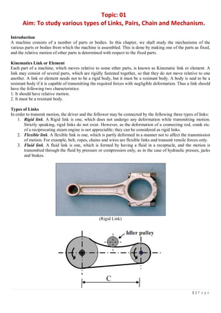
  • 1. 1 | P a g e Topic: 01 Aim: To study various types of Links, Pairs, Chain and Mechanism. Introduction A machine consists of a number of parts or bodies. In this chapter, we shall study the mechanisms of the various parts or bodies from which the machine is assembled. This is done by making one of the parts as fixed, and the relative motion of other parts is determined with respect to the fixed parts. Kinematics Link or Element Each part of a machine, which moves relative to some other parts, is known as Kinematic link or element. A link may consist of several parts, which are rigidly fastened together, so that they do not move relative to one another. A link or element needs not to be a rigid body, but it must be a resistant body. A body is said to be a resistant body if it is capable of transmitting the required forces with negligible deformation. Thus a link should have the following two characteristics: 1. It should have relative motion. 2. It must be a resistant body. Types of Links In order to transmit motion, the driver and the follower may be connected by the following three types of links: 1. Rigid link. A Rigid link is one, which does not undergo any deformation while transmitting motion. Strictly speaking, rigid links do not exist. However, as the deformation of a connecting rod, crank etc. of a reciprocating steam engine is not appreciable; they can be considered as rigid links. 2. Flexible link. A flexible link is one, which is partly deformed in a manner not to affect the transmission of motion. For example, belt, ropes, chains and wires are flexible links and transmit tensile forces only. 3. Fluid link. A fluid link is one, which is formed by having a fluid in a receptacle, and the motion is transmitted through the fluid by pressure or compression only, as in the case of hydraulic presses, jacks and brakes. (Rigid Link)
  • 2. 2 | P a g e (Flexible Link) (Fluid Link) Structure It is an assemblage of a number of resistant bodies (known as members) having no relative motion between them and meant for carrying loads having straining action. A railway bridge, a roof, truss, machine frames etc. are the example of a structure. Kinematic Pair The two links or elements of a machine, when in contact with each other, are said to form a pair. If the relative motion between them is completely or successfully constrained (i.e. in a definite direction), the pair is known as Kinematics pair. Classification of Kinematic Pairs The kinematics pairs may be classified according to the following consideration: 1. According to the type of relative motion between the elements. The kinematics pairs according to type of relative motion between the elements may be classified as discuss below: (a) Sliding pair. When the two elements of a pair are connected in such a way that one can only slide relative to the other, the pair is known as sliding pair. The piston and cylinder, cross-head and guides of a reciprocating steam engine, ram and its guides in shaper, tail stock on the lathe bed etc. are the example of a sliding pair. A little consideration will show that a sliding pair has a completely constrained motion. (b) Turning pair. When the two elements of a pair are connected in such a way that one can only turn or revolve about a fixed axis of another link, the pair is known as turning pair. A shaft with collars at both ends fitted into a circular hole, the crankshaft in a journal bearing in an engine, lathe spindle supported in head stock, cycle wheels turning over their axles etc. are the examples of a turning pair. A turning pair also has a completely constrained motion. (c) Rolling pair. When the two elements of a pair are connected in such a way that one rolls over another fixed link, the pair is known as rolling pair. Ball and other bearings are examples of rolling pair. (d) Screw pair. When the two elements of a pair are connected in such a way that one element can turn about the other by screw threads, the pair is known as screw pair. The lead screw of a lathe with nut, and bolt with a nut are examples of a screw pair. (e) Spherical pair. When the two elements of a pair are connected in such a way that one element (with spherical shape) turns or swivels about the other fixed element, the pair formed is called a spherical pair. The ball and socket joint, attachment of a car mirror, pen stand etc., are the example of a spherical pair.
  • 3. 3 | P a g e (Sliding Pair) (Turning Pair) (Rolling Pair) (Screw Pair) (Spherical Pair) 2. According to the types of contact between the elements. The kinematics pairs according to the type of contact between the elements may be classified as discussed below: (a) Lower pair. When the two elements of a pair have a surface contact when relative motion takes place and the surface of one-element slides over the surface of the other, the pair formed is known as lower pair. (b) Higher pair. When the two element of a pair have a line or point contact when relative motion takes place and the motion between the two elements is partly turning and partly sliding, then the pair is known as higher pair. A pair of friction discs, toothed gearing, belt and rope drives; ball and roller bearings and cam and follower are the examples of higher pair. 3. According to the type of closure. The kinematics pairs according to the types of closure between the elements may be classified as discussed below: (a) Self closed pair. When the two elements of a pair are connected together mechanically in such a way that only required kind of relative motion occurs, it is then known as self-closed pair. The lower pairs are self-closed pair.
  • 4. 4 | P a g e (b) Force-closed pair. When the two elements of a pair are not connected mechanically but are kept in contact by the action of external forces, the pair is said to be a force-closed pair. The cam and follower is an example of force closed pair, as it is kept in contact by the forces exerted by spring and gravity. (Self closed pair) (Force-closed pair) Kinematic Chain When the kinematics pairs are coupled in such a way that the last links is joined to the first link to transmit definite motion (i.e. completely or successfully constrained motion),it is called a kinematics chain. In other words, a kinematics chain may be defined as a combination of kinematics pairs, joined in such a way that each link forms a part of two pairs and the relative motion between the links or elements is completely or successfully constrained. For example, the crankshaft of an engine forms a kinematics pair with the bearing which are fixed in a pair, the connecting rod with the crank forms a second kinematics pair, the piston with the connecting rod forms a third pair and the piston with the cylinder forms a fourth pair. The total combination of these links is a kinematics chain. If each link is assumed to form two pairs with two adjacent links, then the relation between the number of pairs (p) forming a kinematic chain and the number of links (l) may be expressed in the form of an equation: ℓ = 2p – 4 Since in a kinematic chain each link forms a part of two pairs, therefore there will be as many links as the number of pairs. Another relation between the number of links (l) and the number of joints (j) which constitute a kinematic chain is given by the expression: Mechanism When one of the links of a kinematics chain is fixed, the chain is known as mechanism. It may be used for transmitting or transforming motion e.g. engine indicators, typewriter etc. A mechanism with four links is known as simple mechanism and the mechanism with more than four links as compound mechanism. When a mechanism is required to transmit power or to do some particular type of work, it then becomes a machine. In such cases, the various links or elements have to be designed to withstand the forces (both static and kinetic) safely. A little consideration will show that a mechanism may be regarded as a machine in which each part is reduced to the simplest form to transmit the required motion. 3 2 2 j   
  • 5. 5 | P a g e Topic : 02 To study inversion of four Bar Mechanism, Single Slider Crank Chain Mechanism and Double Slider Crank Chain Mechanism. Inversion of Mechanism When one of the links is fixed in a kinematic chain, it is called a mechanism. So we can obtain as many mechanisms as the number of links in a kinematic chain by fixing, in turn, different links in a kinematic chain. This method of obtaining different mechanisms by fixing different links in a kinematics chain is known as inversion of the mechanism. Types of Kinematics Chains The most important kinematics chains are those, which consist of four lower pairs, each pair being a sliding pair or a turning pair. The following three kinematic chains with four lower pairs are used widely: 1. Four bar chain or quadric cycle chain, 2. Single slider crank chain, and 3. Double slider crank chain. Four Bar Chain or Quadric Cycle Chains The simplest and the basic kinematic chain is a four bar chain or quadric cycle chain. It consists of four links; each of them forms a turning pair A, B, C and D. The four links may be of different lengths. As per Grashof‟s law for a four bar mechanism, “the sum of shortest and longest link lengths should not be greater than sum of remaining two links lengths if there is to be continuous relative motion between two links.” Inversions of Four Bar Chain 1. Beam Engine. (Crank and lever mechanism). A part of the mechanism of a beam engine (also of four links) wherein the crank rotates about fixed center A and lever oscillates about a fixed center D. The end E of the lever CDE is connected to a piston rod, which reciprocates due to the rotation of the crank. In other words, the purpose of this mechanism is to convert rotary motion into reciprocating motion.
  • 6. 6 | P a g e 2. Coupling rod of a locomotive (Double crank mechanism). The mechanism of a coupling rod of a locomotive (also known as double crank mechanism) consists of four links. In this mechanism, links AD and BC (having equal length) act as cranks and are connected to the respective wheels. The link CD acts as a coupling rod and the link AB is fixed in order to maintain a constant center-to-center distance between them. This mechanism is meant for transmitting rotary motion from wheel to the other wheel. 3. Watt’s indicator mechanism (Double lever mechanism). A Watt‟s indicator mechanism (also known as Watt‟s straight line mechanism or double lever mechanism) consists of four links. The four links are: fixed link at A, link AC, link CE and link BFD. It may be noted that BF and FD forms one links because these two parts have no relative motion between them. The links CE and BFD act as levers. The displacement of the link BFD is directly proportional to the pressure of gas or steam which acts on the indicator plunger. On any small displacement of the mechanism, the tracing point E at the end of the link CE traces out approximately a straight line. Single Slider Crank Chain Mechanism A single slider crank chain is a modification of the basic four bar chain. It consists of one sliding pair and three turning pairs. It is usually, found in reciprocating steam engine mechanism, IC engines etc. It converts rotary motion into reciprocating motion and vice versa. As the crank rotates, the crosshead reciprocates in the guides and thus the piston reciprocates in the cylinder.
  • 7. 7 | P a g e Inversion of Single Slider Crank Chain 1. Pendulum pump or Bull engine. In this mechanism, the inversion is obtained by fixing the cylinder. In this case, when the crank rotates, the connecting rod oscillates about a pin pivoted to the fixed link at A and piston attached to piston rod reciprocates. The duplex pump which is used to supply of feed water to boilers has two pistons attached to link 1. 2. Oscillating Cylinder Engine. In this mechanism, the connecting rod is fixed. When the crank rotates, the piston attached to piston rod reciprocates and the cylinder oscillates about a pin pivoted to the fixed link. 3. Rotary internal combustion engines or Gnome engine. Sometimes back, rotary internal combustion engines were used in aviation. But now-a-days gas turbines are used in its place. It consists of seven cylinders in one plane and all revolves about fixed center D, while the crank is fixed. In this mechanism, when the connecting rod rotates, the piston reciprocates inside the cylinders. [Bull Engine]
  • 8. 8 | P a g e [Oscillating Cylinder Engine] [Gnome engine] 4. Crank and slotted lever quick return motion mechanism. It is mostly used in shaping, slotting and planning machines. In this mechanism, the link AC (link3) forming the turning pair is fixed. It corresponds to the connecting rod of a reciprocating steam engine. The driving crank CB revolves with uniform angular speed about the fixed center C. A sliding block attached to the crank pin at B slides along the slotted bar AP to the ram which carries the tool and reciprocates along the line of stroke R1R2 .The line of stroke of the ram (i.e.R1R2) is perpendicular to AC produced. Time of cutting stroke Time of return stroke    360 OR 360       
  • 9. 9 | P a g e 5. Whitworth quick return motion mechanism. It is used in shaping and slotting machines. In this mechanism, the link CD (link 2) forming turning pair is fixed. It corresponds to crank in reciprocating steam engine. The driver crank CA (link3) rotates at a uniform angular speed. The slider (link4) A slides along slotted bar PA (link 1) and PA oscillates about pivoted point D. The connecting rod PR, carries ram at R with which cutting tool is fixed. The motion of the tool is constrained along the line RD produced, i.e. along a line passing through D and perpendicular to CD. Double Slider Crank Chain A kinematic chain which consists of two turning pairs and two sliding pairs is known as double slider chain. Inversion of Double Slider Crank Chain 1. Elliptical trammel: It is an instrument used for drawing ellipse. This inversion is obtained by fixing the slotted plate which has two straight grooves cut in it, at right angles to each other. The link 1 and link 3, are known as sliders and form sliding pairs with slotted plate. The link AB (link 2) is a bar, which forms turning pair with links 1 and 3. When Time of cutting stroke Time of return stroke    360 OR 360       
  • 10. 10 | P a g e the links 1and 3 slide along their respective grooves, any point on the link 2 such as P traces out an ellipse with AP and BP are the semi-major axis and semi-minor axis of the ellipse respectively. 2. Scotch yoke mechanism. It is used for converting rotary motion into a reciprocating motion. The inversion is obtained by the fixing either the link1 or link3. Link 1 is fixed. In this mechanism, when the link2 (which corresponds to crank) rotates about B as center, the link 4 (which corresponds to a frame) reciprocates. The fixed link 1 guides the frame. 3. Oldham’s coupling. An Oldham‟s coupling is used for connecting two parallel shafts whose axes are at a small distance apart. The shafts are coupled in such a way that if one shaft rotates, the other shaft also rotates at the same speed. The inversion is obtained by the fixing the link 2. The shafts to be connected have two flanges (link 1 and link 3) rigidly fastened at their ends by forging. The link 1 and link3 form turning pairs with link 2. These flanges have diametrical slots cut in their inner faces. The intermediate piece (link4), which is a circular disc, has two tongues (i.e. diametrical projections) T1 and T2 on each face at right angles to each other. The tongues on the link 4 closely fit into the slots in the two flanges (link 1 and link3). The link 4 can slide or reciprocate in the slots in the flanges.
  • 11. 11 | P a g e Topic: 03 To study various kinds of belts, rope and chain drives. Belt Drives The belts or ropes are used to transmit power from one shaft to another by means of pulleys, which rotate at the same speed or at different speeds. The amount of power transmitted depends upon the following factors: 1. The velocity of belt. 2. The tension under which the belt is placed on the pulleys. 3. The arc of contact between the belt and the smaller pulley. 4. The conditions under which the belt is used. Selection of a Belt Drive Following are the various important factors upon which the selection of a belt depends: 1. Speed of the driving and driven shaft. 2. Speed reduction ratio, 3. Power to be transmitted, 4. Centre distance between the shafts, 5. Positive drive requirements, 6. Shafts layout, 7. Space available, and 8. Service conditions. Types of Belt Drives The belt drives are usually classified into the following three groups: 1. Light drives. These are used to transmit small powers at belt speeds up to about 10m/s, as in agricultural machines and small machine tools. 2. Medium drives. These are used to transmit medium power at belt speeds over 10m/s but up to 22m/s, as machine tools. 3. Heavy drives. These are used to transmit large powers at belt speeds above 22 m/s, as in compressors and generators. Types of Belts Though there are many types of belts used these days, yet the following are important from the subject point of view: 1. Flat belt: - The flat belt is mostly used in the factories and workshops, where a moderate amount of power is to be transmitted, from one pulley to another, when the two pulleys are not more than 8 meters apart. 2. V-Belt: - The V-belt is mostly used in the factories and workshop, where a moderate amount of power is to be transmitted, from one pulley to another, when the two pulleys are very near to each other. 3. Circular belt or rope: - The circular belt or rope, is mostly used in the factories and workshops, where a great amount of power is to be transmitted, from one pulley to another, when the two pulleys are more than 8 meters apart.
  • 12. 12 | P a g e Materials used for belts The material used for belts and ropes must be strong, flexible, and durable. It must have a high coefficient of friction. The belts, according to the material used, are classified as follows: 1. Leather belts. The most important materials for the belt is leather. The best leather belts are made from 1.2 meters to 1.5 meters long strips cut from either side of the back bone of the top grade steer hides. The hair side of the lather is smoother and harder than the flesh side, but the flesh side is stronger. The fibers on the hair side are perpendicular to the surface, while those on the flesh side are interwoven and parallel to the surface. Therefore for these reasons, the hair side of a belt should be in contact with the pulley surface. This gives a more intimate contact between the belt and the pulley and places the greatest tensile strength of the belt section on the outside, where the tension is maximum as the belt over the pulley. 2. Cotton or a fabric belts. Most of the belts are made by folding canvass or cotton duck to three or more layers (depending upon the thickness desired) and stitching together. These belts are woven also into a strip of the desired width and thickness. They are impregnated with some filler like linseed oil in order to make the belts waterproof and to prevent injury to the fibers. The cotton belts are cheaper and suitable in warm climates, in damp atmospheres and in exposed positions. Since the cotton belts require little attention, therefore these belts are mostly used in farm machinery, belt conveyor etc. 3. Rubber belt. The rubber belts are made of layers of fabric impregnated with rubber composition and have a thin layer of rubber on the faces. These belts are very flexible but are quickly destroyed if allowed to come into contact with heat, oil or grease. One of the principle advantages of these belts is that they may be easily made endless. These belts are found suitable for sawmills; pare mills where they are exposed to moisture. Types of Flat Belt Drives The power from one pulley to another may be transmitted by any of the following types of belt drives. 1. Open belt drive. The open belt drive is used with shafts arranged parallel and rotating in the same direction. In this case, the driver A pulls the belt from one side (i.e. lower side RQ) and delivers it to the other side (i.e. upper side LM). Thus the tension in the lower side belt will be more than that in the upper side belt. The lower side belt (because of more tension) is known as tight side whereas the upper side belt (because of less tension) is known as slack side. 2. Crossed or twist belt drive. The crossed or twist belt drive is used with shafts arranged parallel and rotating in the opposite directions. In this case, the driver pulls the belts from one side (i.e. RQ) and delivers it to the other side (i.e. LM). Thus the tension in the belt RQ will be more that that in the belt LM. The belt RQ (because of more tension) is known as tight side, where as belt LM (because of less tension) is known as slack side.
  • 13. 13 | P a g e 3. Quarter turn belt drive. The quarters turn belt drive also known as right angle belt drive is used with shafts arranged at an angle and rotating in one definite direction. In order to prevent the belt from leaving the pulley, the width of the face of the face of the pulley should be greater or equal to 1.4 b, where b is the width of belt. In case the pulleys cannot be arranged, when the reversible motion is desired, then a quarter turn belt drive with guide pulley may be used. 4. Belt drive with idle pulleys. A belt drive with an idler pulley, used with shafts arranged parallel and when an open belt drive cannot be used due to small angle of contact on the smaller pulley. This type of drive is provided to obtain high velocity ratio and when the required belt tension cannot be obtained by the other means. When it is desired to transmit motion from one shaft to several shaft, all arranged in parallel, a belt drive with many idler pulleys, may be employed. 5. Compound belt drive. A compound belt drive, is used when power is transmitted from one shafts to another through a number of pulleys. Rope Drives The rope drives are widely used where a large amount of power is to be transmitted, from one pulley to another, over a considerable distance. It may be noted that the use of flat belts is limited for the transmission of moderate power from one pulley to another when the two pulleys are not more than 8 metres apart. If large amounts of power are to be transmitted by the flat belt, then it would result in excessive belt cross-section. It may be noted that frictional grip in case of rope drives is more than that in V-drive. One of the main advantage of rope drives is that a number of separate drives may be taken from the one driving pulley. For example, in many spinning mills, the line shaft on each floor is driven by ropes passing directly from the main engine pulley on the ground floor. The rope drives use the following two types of ropes : 1. Fibre ropes, and 2. Wire ropes. The fibre ropes operate successfully when the pulleys are about 60 metres apart, while the wire ropes are used when the pulleys are upto 150 metres apart. Fibre Ropes The ropes for transmitting power are usually made from fibrous materials such as hemp, manila and cotton. Since the hemp and manila fibres are rough, therefore the ropes made from these fibres are not very flexible and possesses poor mechanical properties. The hemp ropes have less strength as compared to manila ropes. When the hemp and manila ropes are bent over the sheave (or pulley), there is some sliding of fibres, causing the rope to wear and chafe internally. In order to minimise this defect, the rope fibres are lubricated with a tar, tallow or graphite. The lubrication also makes the rope moisture proof. The hemp ropes are suitable only for hand operated hoisting machinery and as tie ropes for lifting tackle, hooks etc.
  • 14. 14 | P a g e The cotton ropes are very soft and smooth. The lubrication of cotton ropes is not necessary. But if it is done, it reduces the external wear between the rope and the grooves of its sheaves. It may be noted that manila ropes are more durable and stronger than cotton ropes. The cotton ropes are costlier than manila ropes Advantages of Fibre Rope Drives The fibre rope drives have the following advantages : 1. They give smooth, steady and quiet service. 2. They are little affected by out door conditions. 3. The shafts may be out of strict alignment. 4. The power may be taken off in any direction and in fractional parts of the whole amount. 5. They give high mechanical efficiency. Sheave for Fibre Ropes The fiber ropes are usually circular in cross-section as shown in Fig. (a). The sheave for the fiber ropes is shown in Fig. (b). the groove angle of the pulley for rope drives is usually 45°. The grooves in the pulleys are made narrow at the bottom and the rope is pinched between the edges of the V-groove to increase the holding power of the rope on the pulley. Wire Ropes When a large amount of power is to be transmitted over long distances from one pulley to another (i.e. when the pulleys are up to 150 meters apart), then wire ropes are used. The wire ropes are widely used in elevators, mine hoists, cranes, conveyors, hauling devices and suspension bridges. The wire ropes run on grooved pulleys but they rest on the bottom of the grooves and are not wedged between the sides of the grooves. The wire ropes have the following advantage over cotton ropes. 1. These are lighter in weight, 2. These offer silent operation, 3. These can withstand shock loads, 4. These are more reliable, 5. They do not fail suddenly, 6. These are more durable, 7. The efficiency is high, and 8. The cost is low. Ratio of Driving Tensions for Rope Drive The ratio of driving tensions for the rope drive may be obtained in the similar way as V-belts Chain Drives We have seen in belt and rope drives that slipping may occur. In order to avoid slipping, steel chains are used. The chains are made up of rigid links which are hinged together in order to provide the necessary flexibility for
  • 15. 15 | P a g e warping around the driving and driven wheels. The wheels have projecting teeth and fit into the corresponding recesses, in the links of the chain as shown in Fig. The wheels and the chain are thus constrained to move together without slipping and ensures perfect velocity ratio. The toothed wheels are known as sprocket wheels or simply sprockets. These wheels resemble to spur gears. The chains are mostly used to transmit motion and power from one shaft to another, when the distance between the centers of the shafts is short such as in bicycles, motor cycles, agricultural machinery, road rollers, etc. Advantages and Disadvantages of Chain Drive over Belt or Rope Drive Following are the advantages and disadvantages of chain drive over belt or rope drive: Advantages 1. As no slip takes place during chain drive, hence perfect velocity ratio is obtained. 2. Since the chains are made of metal, therefore they occupy less space in width than a belt or rope drive. 3. The chain drives may be used when the distance between the shafts is less. 4. The chain drive gives high transmission efficiency (up to 98 per cent). 5. The chain drive gives less load on the shafts. 6. The chain drive has the ability of transmitting motion to several shafts by one chain only. Disadvantages 1. The production cost of chains is relatively high. 2. The chain drive needs accurate mounting and careful maintenance. 3. The chain drive has velocity fluctuations especially when unduly stretched. Terms Used in Chain Drive The following terms are frequently used in chain drive. 1. Pitch of the chain: It is the distance between the hinge centre of a link and the corresponding hinge centre of the adjacent link as shown in Fig. It is usually denoted by p. 2. Pitch circle diameter of the chain sprocket. It is the diameter of the circle on which the hinge centers of the chain lie, when the chain is wrapped round a sprocket as shown in Fig. The points A, B, C, and D are the hinge centers of the chain and the circle drawn through these centers is Called pitch circle and its diameter (d) is known as pitch circle diameter.
  • 16. 16 | P a g e Classification of Chains The chains, on the basis of their use, are classified into the following three groups: 1. Hoisting and hauling (or crane) chains, 2. Conveyor (or tractive) chains, and 3. Power transmitting (or driving) chains.
  • 17. 17 | P a g e Topic: 04 To study various types of gears and gear trains. Gears are used to transmit motion from one shaft to another shaft or between a shaft and a slide. These are accomplished by successively engaging teeth. In order to prevent the slip between the surfaces, teeth can be made on the surface which can mesh with each-other. The disc which has teeth is known as gears and gears wheels. CLASSIFICATION OF THE GEARS: According to the relative position of their axes gears can be classified as:- A. Parallel shaft gears. B. Intersecting shaft gears C Non-parallel & Non- intersecting shaft gears (skew shaft) (A) PARALLEL SHAFT: i. SPUR GEAR: it has a straight teeth parallel to the axes and thus, are not subjected to axial thrust due to teeth load. Fig ii. SPUR RACK AND PINION: is a special case of a spur gear where it is made of infinite diameter so that the pitch surface is a plane. This combination converts rotary motion into translator motion, or vice-versa. iii. HELICAL GEARS OR HELICAL SPUR GEAR: In this gear teeth are curved, each being helical in shape. Two mating gears have the same helix angle, but have teeth of opposite hands. Disadvantages of having end thrust as there is a force component along the gear axis. iv. DOUBLE HELICAL OR HERRINGBONE GEARS: This gear is equivalent to a pair of helical gears secured together, one having a right-hand helix and other a left-hand helix. Axial thrust which occurs in case of single- helical gears is eliminated in double-helical gears. If the left and right inclination of a double helical gear meets at a common apex and there is no groove in between, the gear is known as herringbone gear. (B) INTERSECTING SHAFT: The motion between the two shafts is equivalent to the rolling of two cones, assuming no slipping. The gears, in general, are known as bevel gears. When the teeth formed on the cones are straight, the gears are known as straight bevel .If the gear of the same size and connecting two shaft at right angle to each other are known as metre gears. When the teeth formed on the cones are inclined, they are known as spiral or helical bevel. In spiral gears with curved teeth but with zero degree spiral angle are known as zero bevel gears .
  • 18. 18 | P a g e (C) NON-PARALLEL & NON- INTERSECTING SHAFT GEARS (SKEW SHAFT) In case of parallel and intersecting shaft, a uniform motion is possible by pure rolling contact. But in case of skew (non- parallel, non-intersecting) shafts, this is not possible. i. Cross helical gears: By a suitable choice of helix angle for the mating gears two shafts can set at any angle Application: - Used for light loads only. - Used to drive fed mechanisms on machine tools. - Small I.C. engines for camshafts & oil pumps. ii.Worm Gears:It is a spiral helical gears, used where large speed reduction are to be transmitted in worm gears, large gear (wheel), usually has a hollow or concave shape such that a portion of the pitch diameter of the gear is enveloped on it. The smaller of the two wheels is called the worm, which also has a large spiral angle. GEAR TRAINS: Definition: Two or more gears are made to mesh with each other to transmit power from one shaft to another. A gear train may consist of spur, bevelor spiral gears. Types of Gear Trains: Following are the different type of gear trains, depending upon the arrangement of wheels: (1) Simple gear train (2) Compound gear train (3) Reverted gear train (4) Epicyclic gear trains. In the first three types of gear trains ,the axes of the shafts over Which the gears are mounted are fixed relative to each other, but in case of epicyclic gear trains, The axes of the shaft on which the gears are mounted may move related to a fixed axis. Simple gear train: Where there is only one gear on each shaft, it is known as simple gear train. When the distance between the two shafts is small, the two gears 1 and 2 Are made to mesh with each other to transmit motion from one shaft to other, as shown in fig. Since the gear 1 drive the gear 2, therefore gear 1 is called the driver and the gear 2 is called the driven or follower. It may be noted that the motion of driven gear is opposite to the motion of driving gear,
  • 19. 19 | P a g e 1 (a) (b) Let, N1= Speed of gear 1(or driver) in R.P.M. N2= Speed of gear 2(or driven or follower)in R.P.M T1= Number of teeth on gear 1,and T2= Number of teeth on gear 2. Since the speed ratio of gear train is the ratio of the speed of the driver to the speed of the driven or follower and ratio of speeds of any pair of gears in mesh is the inverse of their number of teeth, therefore Speed Ratio = 2 1 2 1 T T N N  It may be noted that ratio of the speed of the driven or follower to the speed of the driver is known as train value of the gear train. Mathematically 4 Follower Driver 1 2 3 (c)
  • 20. 20 | P a g e Train value = 2 1 1 2 T T N N  From above, we see that the train value is the reciprocal of speed ratio. Compound Gear Train:- When there are more than one gear on a shaft, It is called a compound train of gear. We have seen in simple gear train, that the idle gears, in a simple train gears do not affect the speed ratio of the system. But these gears are useful in bridging over the space the driver and the driven. But whenever the distance between the driver and the driven or follower has to be bridged over by intermediate gears and at the same time a great (or much less) speed ratio is required, than the advantage of intermediate gears is intensified by providing compound gears on intermediate shafts. In this case, each intermediate shaft has two gears rigidly fixed to it so that they may or follower attached to the next shafts . In a compound train of gears, The gear 1 is driving gear mounted on shaft A; gears 2 and 3 are compound gears which are mounted on shaft B. The gears 4 and 5 are also compound gears which are mounted on shaft C and the gear 6 is the driven gear mounted on shaft D. Let N1 = Speed of driving gear 1, T1 = Number of teeth on driving gear 1, N2, N3………, N6 = Speed of respective gears in R.P.M.and T2, T3………, T6 = Number of teeth on gears. Since gear 1 is in mesh gear 2, therefore its speed ratio is 1 2 2 1 T T N N  …….. (i) Similarly, for gears 3 and 4, speed ratio is
  • 21. 21 | P a g e 3 4 4 3 N N N N  …….. (ii) and for gears 5 and 6, speed ratio is 5 6 6 5 N N N N  …….. (iii) The speed ratio of compound gear train is obtained by multiplying the equation (i), (iii) and (iii), 5 3 1 6 4 2 6 1 * 5 6 1 4 1 2 6 5 4 3 2 1 xT xT T xT xT T x N N or T T x T T x T T N N x N N x N N   i.e. Speed ratio = follower or driven last the of Speed driver first the of Speed = drivers the on teeth of number the of oduct drivens the on teeth of number the of oduct Pr Pr and Train value = driver first the of Speed follower or driven last the of Speed = drives the on teeth of number the of oduct drivers the on teeth of number the of oduct Pr Pr The advantage of a compound train over a simple gear train is that a much larger speed reduction from first shaft to the last can be obtained with small gears. Reverted Gear Train:- When the axis of the first gear (i.e. first driver) and the last gear (i.e. last driven or follower) are co-axial, then the gear train is known as reverted gear train We see that gear 1 (i.e. first driver) drivers the gear 2 (i.e. frist or follower) in the opposite direction. Since the gears 2 and 3 are mounted on the same shaft, therefore they from a compound gear and the gear 3 will rotate in the same direction as that of gear 2. The gear 3 (which is now the second driver) drives the gear 4 (i.e. the last driven or follower) in the same direction as that of gear 1. Thus we see that in a
  • 22. 22 | P a g e reverted gear train, the motion of the gear and the last gear is like. Let T1 = Number of teeth on gear 1. r1 = Pitch circle radius of gear 1, and N1 = Speed of gear 1 in R.P.M. Similarly, T2, T3, T4 = number of teeth on respective gears, r2, r3, r4 = Pitch circle radii of respective gears, and N2, N3, N4 = Speed of respective gears in R.P.M. Since the distance between the centers of the shafts of gears 1 and 2 as well as gears 3 and 4 is same, therefore r1 + r2 = r3 + r4 …….. (i) Also, the circular pitch or module of all gears is assumed be same, therefore number or teeth on each gear is directly proportional to its circumference or radius.  T1 + T2 = T3 + T4 …….. (ii) and Speed ratio = drivers on teeth of number of product drivens on teeth of number of oduct Pr or 3 1 4 2 4 1 xT T xT T N N  …….. (iii) From equation (i), (ii) and (iii), we can determine the number of teeth on each gear for the given centre distance, speed ratio and module only when the number of teeth on one gear is chosen arbitrarily. The reverted gear trains are used in automotive transitions, lathe back gears, industrial speed reducers, and is clock (where the minute and hour hand shafts are co-axial). Epicyclical Gear Train:- We have already discussed that in an epicyclical gear train, the axes of the shafts, over which the gears are mounted, may move relative to a fixed axis. A simple epicyclical gear trains, Where a gear A and the arm C have a common axis at O1 about which they can rotate. The gear B meshes with gear A and has its axis on the arm at 02, about which the gear B can rotate. If the arm is fixed, the gear train is simple and gear A can drive gear B or vice of gear A (i.e.01), then the gear B is forced to rotate upon and around gear A. Such a motion is called epicyclic and the gears members move upon and around another member are known as epicyclic gear trains (epi. Means upon and cyclic means around). The epicyclic gear trains may be simple or compound.
  • 23. 23 | P a g e The epicyclic gear trains are useful for transmitting high velocity ratios with gears of moderate size in a comparatively lesser space. The epicyclic gear trains are used in the back gear of lathe, differential gears of the automobiles, hoists, and pulley blocks, wrist watches etc. Velocity Ratio of Epicyclic Gear Train:- The following two methods may be used finding out the velocity ratio of an epicyclic gear train. 1. Tabular method and 2. Algebraic method. 1. Tabular method: - Consider details, as follows: Let TA = Number of teeth on gear A, and TB = Number of teeth on gear B. First of all, let us suppose that the arm is fixed. Therefore the axes of both the gears are also fixed relative to each other. When the gear A makes one revolution anticlockwise, the gear B will make * TA / TB revolutions clockwise. Assuming the anticlockwise rotation as positive and clockwise as negative, we may say that when gear A makes + 1 revolution, then the gear B will make (-TA / TB) revolutions. This statement of relative motion is entered in the first row of the table (see Table). Secondly, if the gear A makes + x revolutions, then the gear B will make –X x TA / TB revolutions. This statement is entered in the second row of the table. In other words, multiply the each motion (entered in the first row) by x. Thirdly, each element of an epicyclic train + revolutions and entered in the third row. Finally, the motion of each element of the gear train is added up and entered in the fourth row. Step No. Conditions of motion Revolutions of elements Arm C Gear A Gear B 1. Arm fixed-gear A rotates through + 1 revolution i.e. 1 rev. anticlockwise 0 +1 B A T T  2. Arm fixed-gear A rotates through + x revolutions 0 + x B A T T x  3. Add + y revolutions to all elements + y + y + y 4. Total motion + y x + y B A T T x y  A little consideration will show that when two conditions about the motion of rotations of any two elements are known, then the unknown speed to the third element may be obtained by substituting the given data in the third column of the fourth row. 2. Algebraic method:- In this method, the motion of each element of the epicyclic train relative to the arm is set down in the from of equations. The number of equations depends upon the number of elements in the gear train. But the two conditions are, usually, aupplied in any epicyclic train viz. some element is fixed and the other has specified motion. These two conditions are sufficient to solve all the equations; and hence to determine the motion of any element in the epicyclic train. Let the arm C be fixed in an epicyclic gear train . Therefore speed of the gear A relative to the arm C = NA – Nc and, the speed of the gear B relative to the arm C, NB - NC Since the gears A and B are meshing directly, therefore they will revolve in opposite directions.
  • 24. 24 | P a g e  C A C B N N N N   Since the arm C is fixed, therefore its speed, Nc = 0.  B A A B T T N N   If the gear A is fixed, Then NA = 0.  B A C B B A C C B T T N N or T T N O N N      1 The tabular method and hence mostly used in solving problems on epicyclic gear train. DIFFERENTIAL GEAR OF AN AUTOMOBILE:- As long as the automobile is running on a straight path, the rear wheels are driven directly by the engine and speed of both the wheels is same. But when the automobile is taking a turn, the outer wheel will run faster than the inner wheel because at the time the outer rear wheel has to cover more distance then the inner rear wheel. This is achieved by epicyclical gear train with bevel gear as shown in Fig Its function is i) To transmit motion from the engine shaft to the rear driving wheels, and ii) To rotate the rear wheels at different speeds while the automobile is taking a turn. The differential gear used in the gear drive of an automobile is shown in Fig.
  • 25. 25 | P a g e The bevel gear A (known as pinion) is keyed to the propeller shaft driven from the engine shaft through universal coupling. This gear A drives the gear B (known as crown gear) which rotates freely on the axle P. Two equal gears C and D are mounted on two separate parts P and Q of the rear axles respectively. These gears, in turn, mesh with equal pinions E and F which can rotate freely on the spindle provided on the arm attached to gear B. Table Step No. Conditions of motion Revolutions of elements Gear B Gear C Gear E Gear D 1. Gear B fixed-Gear C rotated through + 1 revolution (i.e. 1 revolution anticlockwise) 0 + 1 E C T T  ) ( 1 D C D E E C T T T T x T T      2. Gear B fixed-Gear C rotated through + x revolutions 0 + x E C T T x  -x 3. Add +y revolutions to all elements + y + y + y + y 4. Total motion + y x + y E C T T x y  y-x When the automobile runs on a straight path, the gears C and D must rotate together. These gears are rotated through the spindle on the gear B. The gears E and F do not rotate on the spindle. But when the automobile is taking a turn, the inner rear wheel should have lesser speed than the outer rear wheel and due to relative speed of the inner and outer gears D and C, the gears E and F start rotating about the spindle axis and at the same time revolve about the axle axis. Due to this epicyclical effect, the speed of the inner rear wheel decreases by a certain amount and the speed of the outer rear wheel increases, by the same amount. This may be well understood by drawing the table of motions as follows: From the table, we see that when the gear B, which derives motion from the engine shaft, rotate at y revolutions, then the speed of inner gear D (or the rear axle Q) is less than y by x revolutions and the speed of the outer gear C (or the rear axle P) is greater than y by x revolutions. In other worlds, the two parts of the rear axle and thus the two wheels rotate at two different speeds. We also see from the table that the speed of gear B is the mean of speed of the gears C and D.
  • 26. 26 | P a g e TOPIC: 05 To study various types of Cam and Follower arrangement. TERMINOLOGY USED IN CAM:- Fig. shows a radial cam with reciprocating roller follower. The following terms are important in order to draw the cam profile which is shown in fig. (1) Base Circle: It is the smallest circle that can be drawn to then cam profile. (2) Trace Point: It is a reference point on the follower and is used to generate the pitch curve. In case of knife edge follower, the knife edge represents the trace point pitch curve corresponds to the cam profile. In a roller follower, the centre of the roller represents the trace point. (3) Pressure angle: It is the angle between the direction of the follower motion and a normal to the pitch curve. This angle is very important in designing a cam profile. If the pressure angle is too large, a reciprocating follower wills aim in its bearings. (4) Pitch point: It is a point of the pitch curve of the cam through the pitch points. (5) Pitch circle: It is a circle drawn from the centre of the cam thought he pitch points. (6) Pitch curve: It is the curve generated by the trace point as the follower moves relative to the cam. For a knife edge follower, the pitch curve and the cam profile are same where as for a roller follower; they are separated by the radius of the roller. (7) Prime circle: It is the smallest circle that can be drawn from the center of the cam and tangent in the pitch curve. For a knife edge and a face follower, the circle and the base circle are identical. For a roller, the prime circle is large than the base circle by the radius of the roller. (8) Lift or stroke: It is the maximum of the travel follower from its lowest position to the topmost position. CLASSIFICATION OF CAM: Cams are classified as follows:- A. According to shape of the cam. B. According to the movement of follower (1)Rise- return- rise (R-R-R): In this type is alternate rise and return of the follower with no periods of dwells. The follower has a linear or an angular displacement its use is limited.
  • 27. 27 | P a g e (2) Dwell- rise- return- dwell (D-R-R-D): the cam includes rise and return of the follower after a dwell. This type is frequently used than R-R-R type. (3) Dwell- rise- dwell- return- dwell (D-R-D-R-D): This type of cam is most widely used. As the name implies it has dwelling which is follower by rise and dwell and subsequently by return and dwell. In case the return of the follower is by a fall, the motion may be known as Dwell-Rise-Dwell. C. According to manner of constraint of the follower. CLASSIFICATION OF THE FOLLOWER: (A) ACCORDING TO SHAPE:- The follower is classified as, (1) Knife edge follower (2) Roller follower (3) Flat faced or mushroom follower (4) Spherical follower. (1) Knife- edge follower: When the end of a follower which is in contact with cam has a sharp knife-edge, it called a knife edge follower The sliding motion takes place between the contacting surfaces i.e. the knife-edge and the cam surface. This cam is not of much use as excessive wear occurs at the contacting surface. (2) Roller follower: When the end of the follower in contact with the cam is a roller the follower is termed as roller follower.Here notice to be made that at the contact surface the rolling motion is taking place; hence rate of wear is reduced. In both the knife edge & roller follower side thrust exists between the follower and the guide. Roller follower is extremely used where more space is available such as in stationary gas engines .engines & Oil engines & also in Aircraft engines. (3) Flat faced or mushroom follower: When the contacting end of the follower is a perfectly flat face, it is called a flat-faced follower .Side thrust between the follower & the guide is much .reduced in case of flat-faced follower. Relative motion between the contacting
  • 28. 28 | P a g e surfaces is mostly of sliding nature but wear may be reduced by offsetting the axis of the follower. They are generally used where space is limited such as in cams used in valve mechanism of automobile engines. (4) Spherical faced follower: When the shape of a surface which is in contact with the cam is spherical, the follower is known as Spherical faced follower .The flat end of the follower is machined to a spherical shape in order to minimize high surface stresses produced during operation. (B) ACCORDING TO THE MOTION OF THE FOLLOWER:- The follower are classified as, (1) Reciprocating translating follower (2) Oscillating or rotating follower. (1)Reciprocating or translating follower: When the follower reciprocating in guide as the cam rotates uniformly it is known as reciprocating or translating follower (2) Oscillating or rotating follower: When the uniform rotary motion of the cam is converted into predetermined oscillatory motion of the follower. It is called oscillating or rotary follower (C) ACCORDING TO LOCATION OF LINE OF MOVEMENT:- (1) Redial follower: If the line movement of the follower passes through the centre of rotation of the cam, the follower is known as a radial follower. (2) Offset follower: If the line of movement of the roller follower is offset from the center of rotation of the cam, the follower is known as an offset follower TYPES OF MOTION OF THE FOLLOWER: (1) Simple harmonic motion. (2) Constant acceleration and deceleration. (3) Constant velocity. (4) Cyclonical motion. (1) SIMPLE HARMONIC MOTION: If the cam rotates with moderate speeds, this type of motion can be recommended. Methodology for constructing the cam profile:- (a) Draw a semi circle (harmonic semi circle) with rise or fall as the diameter. (b) Divided this semi circle into “n” (even number) equal division. (c) Divided the cam displacement interval into „n‟ equal division. (d) Project the intercepts of the harmonic semicircle to the corresponding division of the cam displacement interval. (e) Joints the points with a smooth curve to obtain to the required harmonic curve. (2) CONSTANT ACCELERATION AND DECELERATION: There is first half of the follower motion whereas it is deceleration during the later half. The magnitude of the acceleration and the deceleration is the same and constant in the two halves. (3) CONSTANT VELOCITY: Constant velocity of the follower implies that the displacement of the follower is proportional to the cam displacement and slop of the displacement curve is constant.
  • 29. 29 | P a g e (4) CYCLONICAL MOTION: A cycloid a locus a point on circle on a straight line. (a) Divide the cam displacement interval into n equal parts (even parts). (b) Draw the diagonal of the diagram and extend it below. (c) Draw a circle with the center anywhere on the lower portion of the diagonal such that it‟s circumference is equal to the follower displacement, i.e.2πr = h. (d) Divided the circle into n equal arcs and number them. (e) Project the circle points to its vertical diameter and then in a direction parallel to the diagonal of the diagram to the corresponding co-ordinates. Joining the points with a curve gives required cyclonical. To plot follower displacement Vs cam rotation graph for various cam follower arrangement and construct cam profile. 01 Draw the profile of a cam operating a roller follower of 30 mm diameter from the following data: (i) It lifts the follower through 50 mm during 90o rotation with S.H.M. (ii) The follower remains at rest for next 300 of cam rotation. (iii) The follower is then descent to its original position during 600 of cam rotation with uniform acceleration and retardation. (iv) It remains at rest for the rest of cam rotation. Least radius of cam is 50 mm. If it rotates at 300 rpm, find maximum velocity and acceleration during ascent and descent. 02 Construct cam profile for a knife edge follower. Minimum radius of cam = 30mm, Stroke of follower = 24mm, Angle of rise = 900 , Dwell after rise = 600 , Angle of return = 1200 , Dwell after return for rest of the period. Follower to move outwards with uniform velocity and return back with simple harmonic motion. The follower is offset to right by 15mm. The cam is to rotate in anticlockwise direction 03 A cam operates a flat faced follower which moves with cycloidal motion during ascent and descent. The further specifications are: Min radius of cam=30 mm Angle of ascent =1200 Angle of dwell=600 Lift of follower = 40 mm Angle of decent=900 speed of cam =300rpm Draw cam profile. Find max velocity and acceleration during ascent and decent 04 Draw a cam profile to drive an oscillating roller follower to the specifications given below. (1)Follower to move outwards through an angular displacement of 200 during the first 1200 rotation of the cam; (2) Follower to return to its initial position during next 120o rotation of the cam. (3)Follower to dwell during the next 120o of cam rotation. The distance between pivot centre and roller centre=120mm;distance between Pivot centre and cam axis =130mm;minimum radius of cam=40mm;radius of roller=10mm Inward and outward strokes take place with simple harmonic motion.
  • 30. 30 | P a g e Tutorial - Gear and Gear trains Theory Questions 1 Explain Gear Tooth terminology. 2 Enlist different types of gear train. Explain compound gear train with neat sketch. Also derive the equation of the velocity ratio for compound gear train 3 Explain with a neat sketch the “Differential Gear Box” 4 Explain what is meant by the term “Interference” as related to toothed gears having profile? Discuss various methods used to avoid interference. 5 Explain epicyclic gear train with the help of neat sketch. Write its merits and demerits as compared to reverted and compound gear trains 6 Explain with the neat sketch the “sun and planet wheel”. 7 Derive an expression for the length of the path of contact for two involutes profile gear in mesh. 8 Evaluate – “The common normal at the point of contact between a pair of teeth must always pass through the pitch point”- law of gearing. Examples 1 Two mating involute spur gear of 20 degree pressure angle have a gear ratio of 2. The number of teeth on the pinion is 20 and its speed is 250 rpm. Module pitch of the teeth is 12 mm. Find: (1) The addendum for pinion (2) The addendum for gear wheel & (3) The length of the arc of contact. Assume pinion to be the driver 2 A pair 20o involute gears has module of 5 mm. the pinion has 20 teeth and gear has 60 teeth. Addendum on the pinion and gear wheel in terms of module is 1. Find the followings. (i) Number of pairs in contact (ii) Angle turned through by the pinion and gear wheel for one pair in contact. 3 Determine the minimum no of teeth required on pinion and wheel to avoid interference when gear ratio is 3 and when number of teeth on pinion and wheel is equal(take pressure angle= 20 and addendum of wheel is 1 module.) 4 Two 20° involute spur gear mesh externally and give a velocity ratio of 3. The module is 3 mm and the addendum is equal to 1.1 modules. If the pinion rotates at 120 rpm, determine: minimum number of teeth on each wheel to avoid interference (ii) Contact Ratio 5 In a reverted epicyclic gear train, the arm A carries two gears B and C and a compound gear D-E. The gear B meshes with gear E and the gear C meshes with gear D. The number of teeth an gears B, C, and D are 75, 30 and 90 respectively. Find the speed and direction of gear C when gear B is fixed and the arm A makes 100 R.P.M. clockwise. 6 Fig. shows an epicyclic gear train.Pinion A has 15 teeth and is rigidly fixed in motor shaft. The wheel B has 20 teeth and gears with A, and also with annular fixed wheel D. Pinion C has 15 teeth and is integral with B(C, B being a compound gear wheel). Gear C meshes with annular wheel E, which is keyed to the machine shaft. The arm rotates about the same shaft on which A is fixed and carries the compound wheel B, C. If the motor runs at 1000 rpm, find the speed of the machine shaft. Find the torque exerted on the machine shaft if motor develops a torque of 100 Nm.
  • 31. 31 | P a g e 7 An epicyclic gear train of Sun and Planet type has the fixed outer annular A, Sun Wheel S rotating at a speed of 720 revolutions per minute in clockwise direction and the Arm E carrying three planet wheels P needed to be driven. If diametral pitch is same for all mating gears and Sun Wheel S and Planet wheels P have 15 and 45 teeth respectively, Determine 1. No. of teeth on Annular A 2. Speed and direction of rotation of planets. 8 An epicyclic gear train as shown in fig has a sun wheel S of 30 teeth and two planet wheels P of 50 teeth. The planet wheel mesh with the internal teeth of a fixed annular A. The driving shaft carrying the sun wheel transmits 4 KW at 300 rpm. The driven shaft is connected to an arm which carries the planet wheel. Determine the speed of the driven shaft