Downloaded 1,147 times


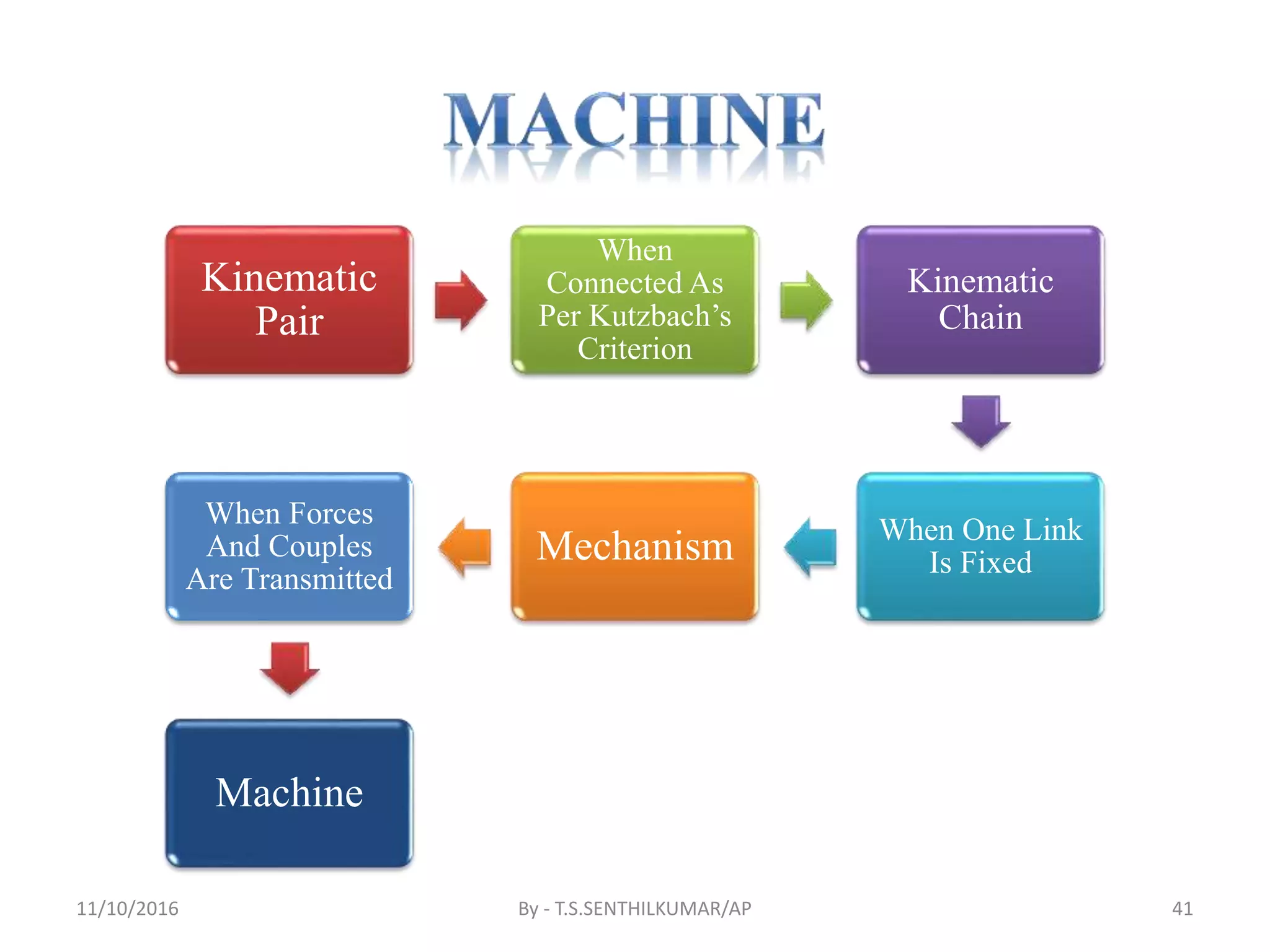


The document provides an overview of mechanics, which is divided into statics and dynamics, and delves into kinematics and kinetics. It explains mechanisms and machines, outlining their components, definitions, and types of links and pairs that facilitate motion. Additionally, it discusses kinematic chains, degrees of freedom, and the criteria for analyzing and classifying mechanisms.