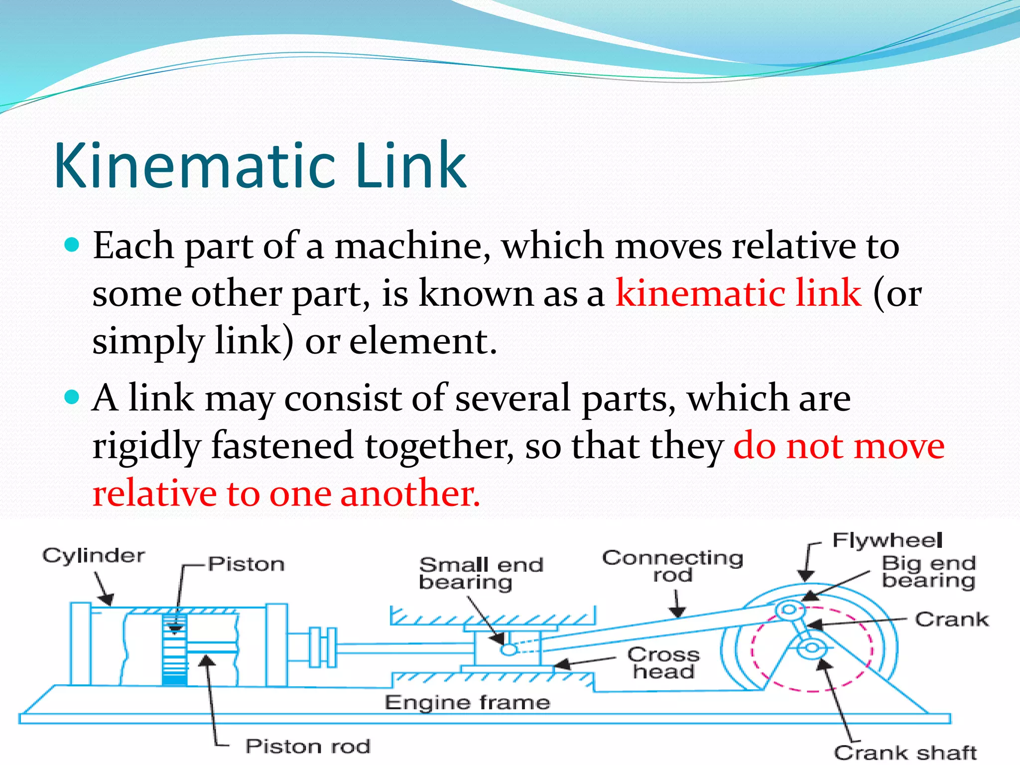
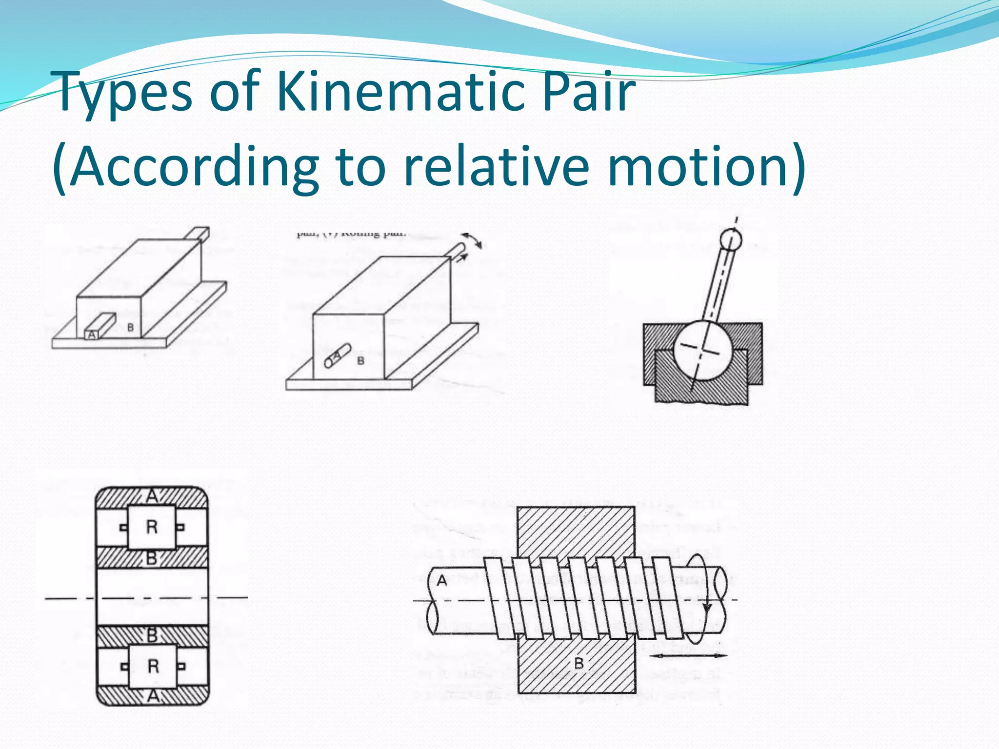
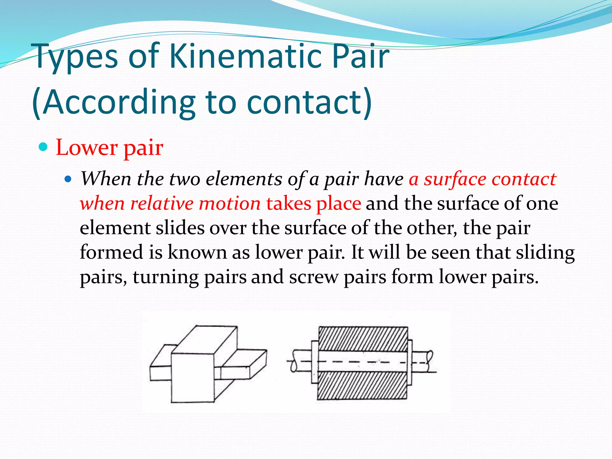
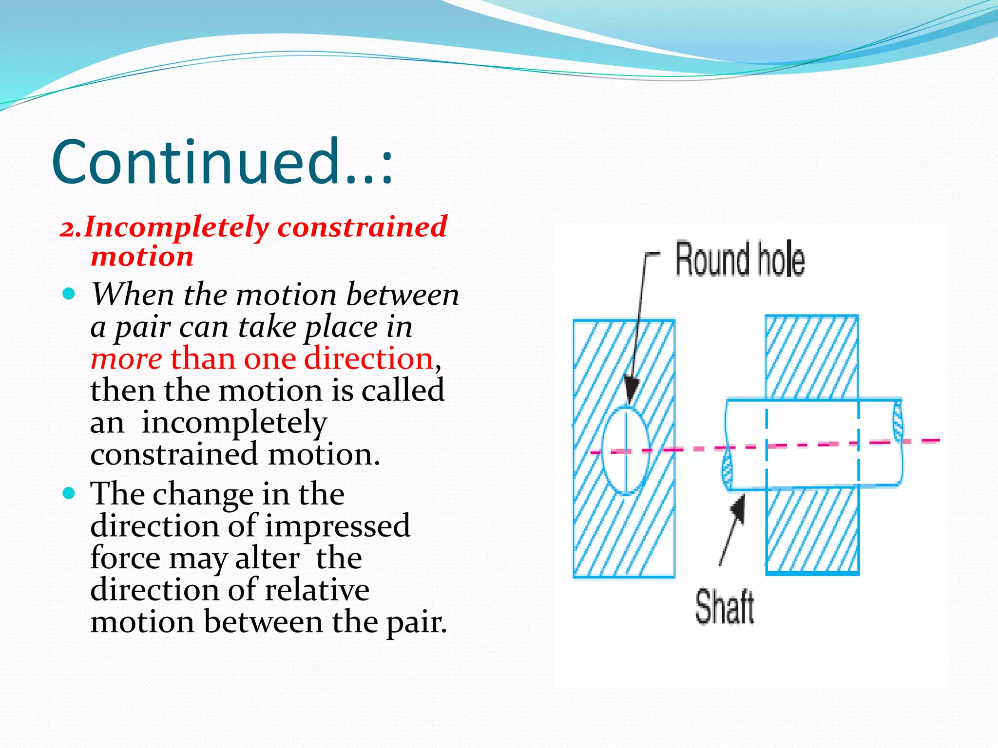
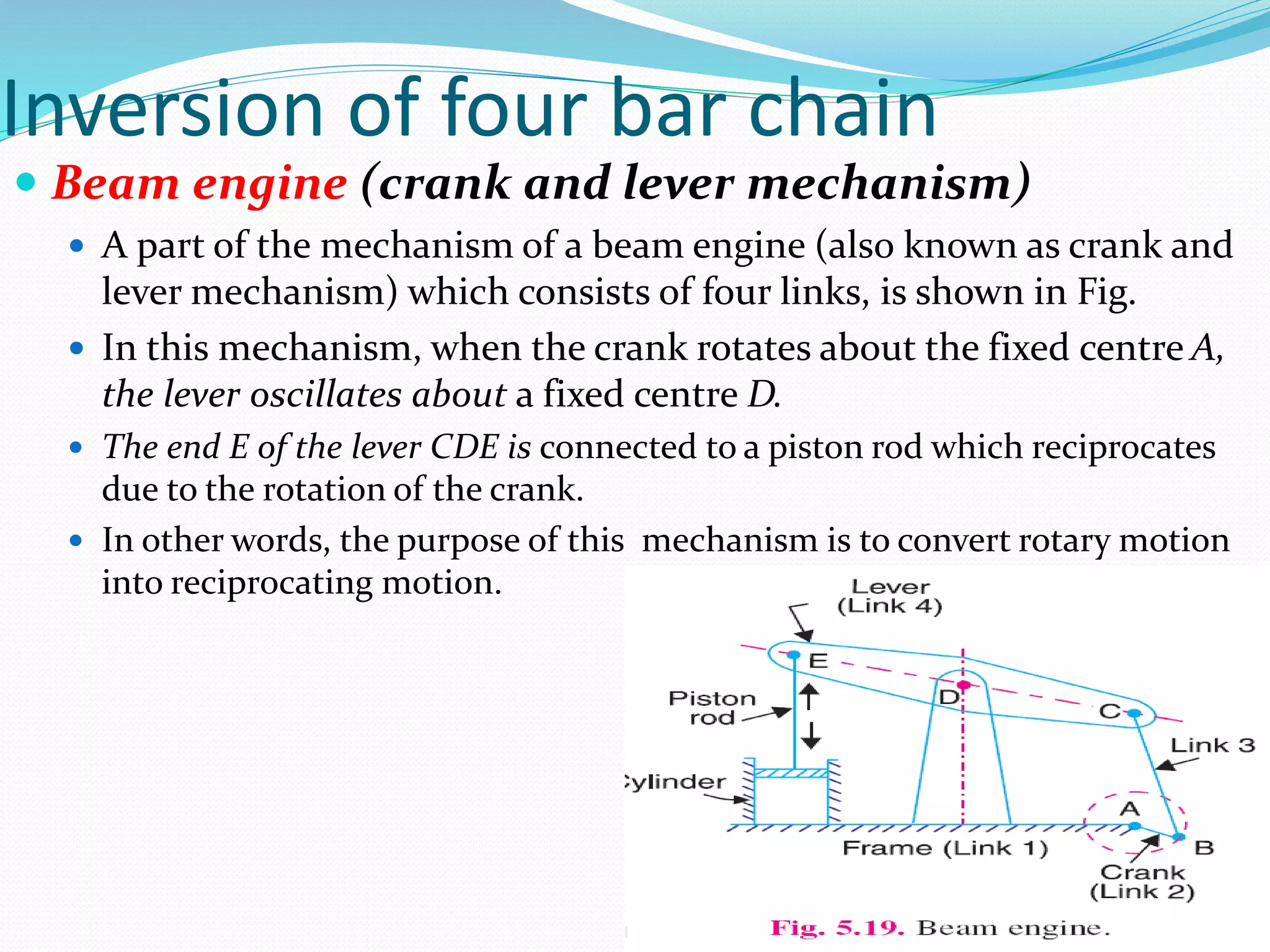
Kinematics of Mechanics
Topic:~Introduction of Mechanisms and
Machines
MECHANICAL DIPARTMENT
Prepared By
 Kushal Panchal
Beginning of “KOM”
 In the starting of Kinematics of Machines we need to
understand the concepts of ‘Kinematics’ and ‘Dynamics’.
 Kinematics of mechanisms is concerned with the motion
of the parts without considering how the influencing
factors (force and mass) affect the motion. Therefore,
kinematics deals with the fundamental concepts.
 Kinetics deals with action of forces on bodies.
 Dynamics is the combination of kinematics and kinetics.
 Dynamics of mechanisms concerns the forces that act on
the parts -- both balanced and unbalanced forces, taking
into account the masses and accelerations of the parts as
well as the external forces.
Basics…:
 The basic of KOM is include
“Mechanisms” and “Machines”.
 The word Mechanism has many
meanings. In kinematics, a
mechanism is a means of
transmitting, controlling, or
constraining relative movement
.
 Movements which are
electrically, magnetically,
pneumatically operated are
excluded from the concept of
mechanism.
 The central theme for
mechanisms is rigid bodies
connected together by joints.
Basics…:
 A machine is a combination
of rigid or resistant bodies,
formed and connected do
that they move with definite
relative motions and transmit
force from the source of
power to the resistance to be
overcome.
 A machine has two
functions: transmitting
definite relative motion and
transmitting force. These
functions require strength
and rigidity to transmit the
forces.
Classification of “Mechanisms”
 Mechanisms can be divided into planar mechanisms and
spatial mechanisms, according to the relative motion of the
rigid bodies.
 In a planar mechanisms, all of the relative motions of the
rigid bodies are in one plane or in parallel(2D) planes.
 If there is any relative motion that is not in the same plane
or in parallel planes(3D), the mechanism is called the
spatial mechanism.
 In other words, planar mechanisms are essentially two
dimensional while spatial mechanisms are three
dimensional.
Kinematic Link
 Each part of a machine, which moves relative to
some other part, is known as a kinematic link (or
simply link) or element.
 A link may consist of several parts, which are
rigidly fastened together, so that they do not move
relative to one another.
Types of Link
Rigid link.
A rigid link is one which does not undergo any deformation while
transmitting motion. Strictly speaking, rigid links do not exist.
However, as the deformation of a connecting rod, crank etc. of a
reciprocating steam engine is not appreciable, they can be
considered as rigid links.
Flexible link.
A flexible link is one which is partly deformed in a manner not to
affect the transmission of motion. For example, belts, ropes, chains
and wires are flexible links and transmit tensile forces only.
Fluid link.
A fluid link is one which is formed by having a fluid in a receptacle
and the motion is transmitted through the fluid by pressure or
compression only, as in the case of hydraulic presses, jacks and
brakes.
Kinematic Pair
 The two links or
elements of a machine,
when in contact with
each other, are said to
form a pair. If the relative
motion between them is
completely or
successfully constrained
(i.e. in a definite
direction), the pair is
known as kinematic pair.
Types of Kinematic Pair
(According to relative motion)
Types of Kinematic Pair
(According to contact)
 Lower pair
 When the two elements of a pair have a surface contact
when relative motion takes place and the surface of one
element slides over the surface of the other, the pair
formed is known as lower pair. It will be seen that sliding
pairs, turning pairs and screw pairs form lower pairs.
Types of Kinematic Pair
(According to contact)
 Higher pair
 When the two elements of a pair have a line or point
contact when relative motion takes place and the motion
between the two elements is partly turning and partly
sliding, then the pair is known as higher pair.
 A pair of friction discs, toothed gearing, belt and rope
drives, ball and roller bearings and cam and follower are
the examples of higher pairs.
Types of ‘Constrain Motion’
1.Completely constrained
motion
 When the motion between a
pair is limited to a definite
direction irrespective of the
direction of force applied,
then the motion is said to
be a completely constrained
motion.
 The motion of a square bar
in a square hole, as shown
in Fig. 2, and the motion of
a shaft with collars at each
end in a circular hole, as
shown in Fig.
Continued..:
2.Incompletely constrained
motion
 When the motion between
a pair can take place in
more than one direction,
then the motion is called
an incompletely
constrained motion.
 The change in the
direction of impressed
force may alter the
direction of relative
motion between the pair.
Continued..:
3.Successfully constrained
motion
 When the motion between the
elements, forming a pair, is
such that the constrained
motion is not completed by
itself, but by some other
means, then the motion is
said to be successfully
constrained motion.
 The motion of an I.C. engine
valve and the piston
reciprocating inside an
engine cylinder are also the
examples of successfully
constrained motion.
Kinematic Chain
 When the kinematic pairs are coupled in such a way that
the last link is joined to the first link to transmit definite
motion (i.e. completely or successfully constrained
motion), it is called a kinematic chain.
 In other words, a kinematic chain may be defined as a
combination of kinematic pairs, joined in such a way that
each link forms a part of two pairs and the relative motion
between the links or elements is completely or successfully
constrained.
Continued..:
 If each link is assumed to form two pairs with two adjacent links, then the
relation between the number of pairs ( p ) forming a kinematic chain and the
number of links ( l ) may be expressed in the form of an equation :
 Since in a kinematic chain each link forms a part of two pairs, therefore there
will be as many links as the number of pairs.
 Another relation between the number of links (l) and the number of joints ( j )
which constitute a kinematic chain is given by the expression :
 If in the example
 L.H.S>R.H.S That’ll be considered as “Locked Chain”.
 L.H.S=R.H.S That’ll be considered as “One D.O.F”.
 L.H.S<R.H.S That’ll be considered as “Unconstrained Chain”.
42  pl
2
2
3
 lj
Example…..
Degree of freedom
 Degrees of freedom/mobility of a mechanism:
 It is the number of inputs (number of independent
coordinates) required to describe the configuration or
position of all the links of the mechanism, with respect
to the fixed link at any given instant.
 Grubler’s equation:
hjln  2)1(3
Example of DOF..
When one of links is fixed in a kinematic chain, its
called mechanism. So we can obtain many mechanism
by fixing, in turn, different links in kinematic chain.
This method is known as “inversion of mechanism”.
Inversion of four bar chain
(quadric cycle chain)
Inversion of four bar chain
 Beam engine (crank and lever mechanism)
 A part of the mechanism of a beam engine (also known as crank and
lever mechanism) which consists of four links, is shown in Fig.
 In this mechanism, when the crank rotates about the fixed centre A,
the lever oscillates about a fixed centre D.
 The end E of the lever CDE is connected to a piston rod which reciprocates
due to the rotation of the crank.
 In other words, the purpose of this mechanism is to convert rotary motion
into reciprocating motion.
Inversion of four bar chain
 Coupling rod of a locomotive (Double crank
mechanism).
 Watt’s indicator mechanism (Double lever
mechanism).
Single Slider Crank Chain
 A single slider crank chain is a modification of the
basic four bar chain.
 It consist of one sliding pair and three turning pairs. It
is, usually, found in reciprocating steam engine
mechanism.
 This type of mechanism converts rotary motion into
reciprocating motion and vice versa.
Inversions of Single Slider Crank
Chain
1. Pendulum pump or Bull
engine.
2.Oscillating cylinder
engine
3. Rotary internal
combustion engine
4.Crank and slotted lever
quick return motion
mechanism.
5.Whitworth quick return
motion mechanism.
Inversion of double slider
mechanism
 Elliptical trammels
 Scotch yoke mechanism
 Oldham’s coupling
Elliptical trammels.
Scotch yoke mechanism.
Oldham’s coupling.
Thank You.

Kinemetic chains, Pairs, Joints, Four bar Mechanisms (KOM)

  • 1.
    Kinematics of Mechanics Topic:~Introductionof Mechanisms and Machines MECHANICAL DIPARTMENT
  • 2.
  • 3.
    Beginning of “KOM” In the starting of Kinematics of Machines we need to understand the concepts of ‘Kinematics’ and ‘Dynamics’.  Kinematics of mechanisms is concerned with the motion of the parts without considering how the influencing factors (force and mass) affect the motion. Therefore, kinematics deals with the fundamental concepts.  Kinetics deals with action of forces on bodies.  Dynamics is the combination of kinematics and kinetics.  Dynamics of mechanisms concerns the forces that act on the parts -- both balanced and unbalanced forces, taking into account the masses and accelerations of the parts as well as the external forces.
  • 4.
    Basics…:  The basicof KOM is include “Mechanisms” and “Machines”.  The word Mechanism has many meanings. In kinematics, a mechanism is a means of transmitting, controlling, or constraining relative movement .  Movements which are electrically, magnetically, pneumatically operated are excluded from the concept of mechanism.  The central theme for mechanisms is rigid bodies connected together by joints.
  • 5.
    Basics…:  A machineis a combination of rigid or resistant bodies, formed and connected do that they move with definite relative motions and transmit force from the source of power to the resistance to be overcome.  A machine has two functions: transmitting definite relative motion and transmitting force. These functions require strength and rigidity to transmit the forces.
  • 6.
    Classification of “Mechanisms” Mechanisms can be divided into planar mechanisms and spatial mechanisms, according to the relative motion of the rigid bodies.  In a planar mechanisms, all of the relative motions of the rigid bodies are in one plane or in parallel(2D) planes.  If there is any relative motion that is not in the same plane or in parallel planes(3D), the mechanism is called the spatial mechanism.  In other words, planar mechanisms are essentially two dimensional while spatial mechanisms are three dimensional.
  • 8.
    Kinematic Link  Eachpart of a machine, which moves relative to some other part, is known as a kinematic link (or simply link) or element.  A link may consist of several parts, which are rigidly fastened together, so that they do not move relative to one another.
  • 9.
    Types of Link Rigidlink. A rigid link is one which does not undergo any deformation while transmitting motion. Strictly speaking, rigid links do not exist. However, as the deformation of a connecting rod, crank etc. of a reciprocating steam engine is not appreciable, they can be considered as rigid links. Flexible link. A flexible link is one which is partly deformed in a manner not to affect the transmission of motion. For example, belts, ropes, chains and wires are flexible links and transmit tensile forces only. Fluid link. A fluid link is one which is formed by having a fluid in a receptacle and the motion is transmitted through the fluid by pressure or compression only, as in the case of hydraulic presses, jacks and brakes.
  • 10.
    Kinematic Pair  Thetwo links or elements of a machine, when in contact with each other, are said to form a pair. If the relative motion between them is completely or successfully constrained (i.e. in a definite direction), the pair is known as kinematic pair.
  • 11.
    Types of KinematicPair (According to relative motion)
  • 12.
    Types of KinematicPair (According to contact)  Lower pair  When the two elements of a pair have a surface contact when relative motion takes place and the surface of one element slides over the surface of the other, the pair formed is known as lower pair. It will be seen that sliding pairs, turning pairs and screw pairs form lower pairs.
  • 13.
    Types of KinematicPair (According to contact)  Higher pair  When the two elements of a pair have a line or point contact when relative motion takes place and the motion between the two elements is partly turning and partly sliding, then the pair is known as higher pair.  A pair of friction discs, toothed gearing, belt and rope drives, ball and roller bearings and cam and follower are the examples of higher pairs.
  • 14.
    Types of ‘ConstrainMotion’ 1.Completely constrained motion  When the motion between a pair is limited to a definite direction irrespective of the direction of force applied, then the motion is said to be a completely constrained motion.  The motion of a square bar in a square hole, as shown in Fig. 2, and the motion of a shaft with collars at each end in a circular hole, as shown in Fig.
  • 15.
    Continued..: 2.Incompletely constrained motion  Whenthe motion between a pair can take place in more than one direction, then the motion is called an incompletely constrained motion.  The change in the direction of impressed force may alter the direction of relative motion between the pair.
  • 16.
    Continued..: 3.Successfully constrained motion  Whenthe motion between the elements, forming a pair, is such that the constrained motion is not completed by itself, but by some other means, then the motion is said to be successfully constrained motion.  The motion of an I.C. engine valve and the piston reciprocating inside an engine cylinder are also the examples of successfully constrained motion.
  • 17.
    Kinematic Chain  Whenthe kinematic pairs are coupled in such a way that the last link is joined to the first link to transmit definite motion (i.e. completely or successfully constrained motion), it is called a kinematic chain.  In other words, a kinematic chain may be defined as a combination of kinematic pairs, joined in such a way that each link forms a part of two pairs and the relative motion between the links or elements is completely or successfully constrained.
  • 18.
    Continued..:  If eachlink is assumed to form two pairs with two adjacent links, then the relation between the number of pairs ( p ) forming a kinematic chain and the number of links ( l ) may be expressed in the form of an equation :  Since in a kinematic chain each link forms a part of two pairs, therefore there will be as many links as the number of pairs.  Another relation between the number of links (l) and the number of joints ( j ) which constitute a kinematic chain is given by the expression :  If in the example  L.H.S>R.H.S That’ll be considered as “Locked Chain”.  L.H.S=R.H.S That’ll be considered as “One D.O.F”.  L.H.S<R.H.S That’ll be considered as “Unconstrained Chain”. 42  pl 2 2 3  lj
  • 19.
  • 20.
    Degree of freedom Degrees of freedom/mobility of a mechanism:  It is the number of inputs (number of independent coordinates) required to describe the configuration or position of all the links of the mechanism, with respect to the fixed link at any given instant.  Grubler’s equation: hjln  2)1(3
  • 21.
  • 22.
    When one oflinks is fixed in a kinematic chain, its called mechanism. So we can obtain many mechanism by fixing, in turn, different links in kinematic chain. This method is known as “inversion of mechanism”.
  • 23.
    Inversion of fourbar chain (quadric cycle chain)
  • 24.
    Inversion of fourbar chain  Beam engine (crank and lever mechanism)  A part of the mechanism of a beam engine (also known as crank and lever mechanism) which consists of four links, is shown in Fig.  In this mechanism, when the crank rotates about the fixed centre A, the lever oscillates about a fixed centre D.  The end E of the lever CDE is connected to a piston rod which reciprocates due to the rotation of the crank.  In other words, the purpose of this mechanism is to convert rotary motion into reciprocating motion.
  • 25.
    Inversion of fourbar chain  Coupling rod of a locomotive (Double crank mechanism).  Watt’s indicator mechanism (Double lever mechanism).
  • 27.
    Single Slider CrankChain  A single slider crank chain is a modification of the basic four bar chain.  It consist of one sliding pair and three turning pairs. It is, usually, found in reciprocating steam engine mechanism.  This type of mechanism converts rotary motion into reciprocating motion and vice versa.
  • 28.
    Inversions of SingleSlider Crank Chain 1. Pendulum pump or Bull engine. 2.Oscillating cylinder engine 3. Rotary internal combustion engine 4.Crank and slotted lever quick return motion mechanism. 5.Whitworth quick return motion mechanism.
  • 30.
    Inversion of doubleslider mechanism  Elliptical trammels  Scotch yoke mechanism  Oldham’s coupling
  • 31.
  • 32.
  • 33.
  • 34.