Download to read offline


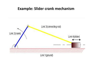

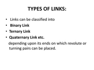


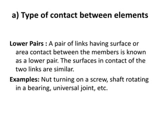
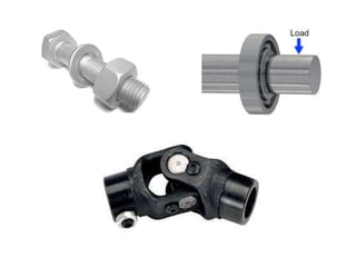


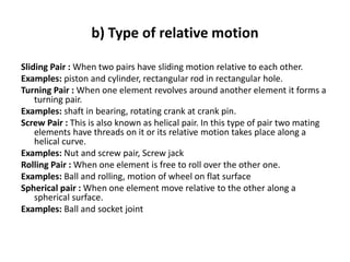


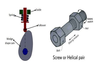

This document discusses links and kinematic pairs in mechanical mechanisms. It defines a link as a single resistant body or combination of bodies with inflexible connections that moves relative to other parts. Links are classified by the number of ends they connect to other links. Kinematic pairs connect links and allow relative motion between them. Pairs are classified by their type of contact, relative motion, and constraint between links. Common pairs include turning, sliding, rolling, and screw pairs. The document provides examples of links and pairs in slider-crank mechanisms.