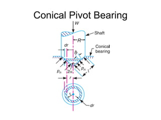
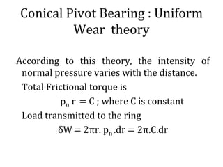
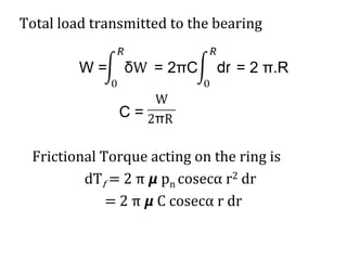
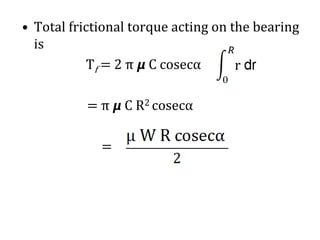
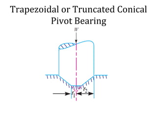
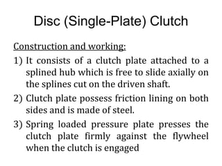
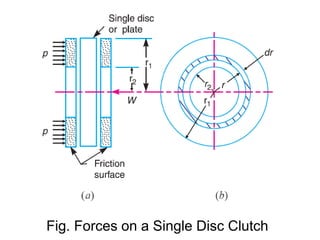
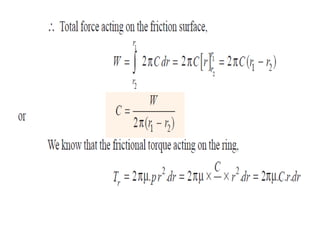
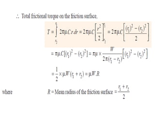
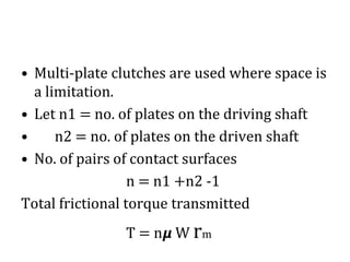
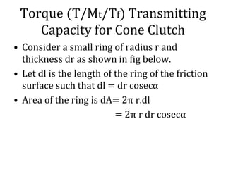
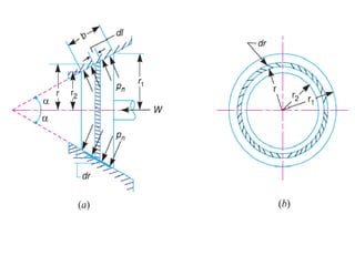
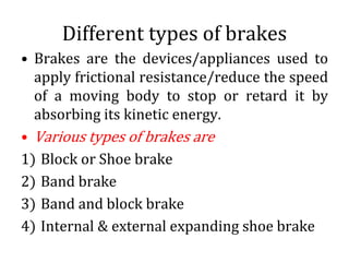
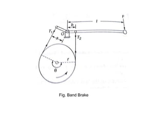
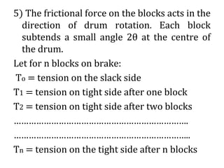
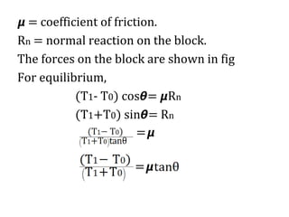
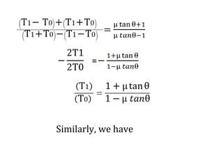
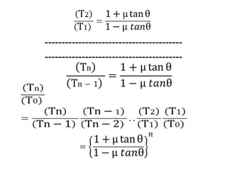
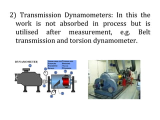
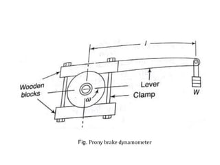
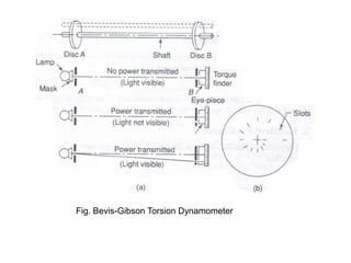
Friction Clutches
© Dr. V.R Deulgaonkar 2018
Introduction
• A clutch is a device used to transmit the
rotary motion of one shaft to another when
desired.
• It is mechanical device that is used to
connect or disconnect the source of power
from the remaining parts of the power
transmission system at the will of operator.
• An automotive clutch can permit the engine
to run without driving the car. It is desired
when engine is to be started or stopped or
when gears are to be shifted.
Friction Clutches
• In friction clutches, the connection of the
engine shaft to the gear box is affected by
friction between two or more rotating
concentric surfaces.
• In these clutches, power transmission is
achieved by means of friction between the
contacting surfaces.
Pivot Friction
• The rotating shafts are frequently subjected
to axial thrust. Pivots are the bearing
surfaces which are used to take the axial
thrust of the rotating shaft. Common
examples are propeller shafts of ships, the
shafts of steam turbines and vertical
machine shafts.
• The pivots may have flat, conical and
trapezoidal or truncated surfaces.
Types of Pivots
Flat Pivot or Foot step Bearing
• When a vertical
shaft rotates in a
flat pivot bearing as
shown, the sliding
friction will be
along the surface of
contact between the
shaft and the
bearing.
Flat Pivot Bearing : Uniform
Pressure theory
• In the fig shown let
W = Load on the bearing or load transmitted
over the bearing surface.
R = Radius of bearing surface.
p = Intensity of pressure between the rubbing
surfaces.
According to uniform pressure theory, we
know that,
• When the pressure is uniformly distributed
over the bearing surface area, then
R2
Now consider a ring of radius r and thickness
dr as shown.
Area of bearing surface, ΔA = 2 πr dr
Load transmitted to the ring, ΔW = p . ΔA
Frictional resistance to sliding at radius r,
Fr = 𝞵 . ΔW = 2 π𝞵. pr .dr
Frictional torque on the ring
dTf = Fr . r =
Total frictional torque = Tf
Power Lost in Friction
P = Tf ω
But , we know that
N = Speed of the shaft in rpm
• If the shaft of radius R2 is resting on a disc of
radius R1, then
Flat Pivot Bearing : Uniform
Wear Theory
• The rate of wear depends upon the intensity of
pressure and the rubbing velocity. The rubbing
velocity increases with the increase in radius.
Hence the wear rate is proportional to the
product of pressure and radius.
• For uniform wear
pr = C (C= constant)
p =
• Load transmitted to the ring
δW = p.2πr dr
= 2πC dr
Total load transmitted to the bearing is
W,
W = 2πC dr
W = 2πCR and
C =
Frictional torque acting on the ring
dTf = 2 π 𝞵 p r2 dr
= 2 π 𝞵 C r dr (as pr = C)
Total friction torque on the bearing is Tf
Tf = 2 π 𝞵 C r dr
Tf = π 𝞵 C R2
= 𝞵 W
If the shaft of radius R2 is resting on a disc of
inner radius R1, then
Conical Pivot Bearing
Consider a conical pivot bearing as shown in fig
above
pn = intensity of normal pressure on the cone
α = semi-cone angle
𝞵 = coefficient of friction between the shaft and
bearing
R = radius of the shaft
Consider a small ring of radius r and thickness
dr. Let dl be the length of the ring along the
cone, so that dl = dr cosecα
Area of the ring dA = 2πr dl = 2πr dr cosecα
Conical Pivot Bearing : Uniform
Pressure theory
Normal load acting on the ring
δWn = 2πr. pn .dr cosecα
Vertical load acting on the ring,
δW= δWn Sinα
Total vertical load transmitted to the bearing
is given as
W = = 2πr. pn
= π pn
or
pn =
Frictional force acting on the ring tangentially
at radius r is given as
Ff = 𝞵 δWn
Frictional torque acting on the ring
dTf = Ff .r = 2π 𝞵 pn cosecα .r2 .dr
Total Frictional torque is
Conical Pivot Bearing : Uniform
Wear theory
According to this theory, the intensity of
normal pressure varies with the distance.
Total Frictional torque is
pn r = C ; where C is constant
Load transmitted to the ring
δW= 2πr. pn .dr = 2π.C.dr
Total load transmitted to the bearing
W = = 2πC = 2 π.R
C =
Frictional Torque acting on the ring is
dTf = 2 π 𝞵 pn cosecα r2 dr
= 2 π 𝞵 C cosecα r dr
• Total frictional torque acting on the bearing
is
Tf = 2 π 𝞵 C cosecα
= π 𝞵 C R2 cosecα
=
Trapezoidal or Truncated Conical
Pivot Bearing
Intensity of Uniform Pressure
pn =
The truncated conical pivot bearing is further
evaluated using uniform pressure and
uniform wear theories.
For uniform pressure the total frictional torque
is T or (Tf) and is given as
Uniform Pressure Theory
Uniform Wear Theory
We know that Total load transmitted to the
ring is
W = = 2πC (r2-r1)
C =
For uniform wear the total frictional torque is
T or (Tf) and is given as
Flat Collar Bearing
A single collar bearing and a multiple collar
bearing are shown in fig (a) and (b) above
r1, r2 = outer and inner radii of the bearing
When pressure is uniformly distributed over the
bearing surface the intensity of pressure is given
as
Total Frictional torque is given as T or(Tf)
Flat Collar Bearing: Uniform
Wear
For uniform wear, load transmitted to the ring
δW= 2πr. pn .dr = 2π.C.dr
Frictional Torque acting on the ring is
dTf = 𝞵 δW r = 2π. 𝞵 .C. r.dr
= 𝞵W rm
Disc (Single-Plate) Clutch
Construction and working:
1) It consists of a clutch plate attached to a
splined hub which is free to slide axially on
the splines cut on the driven shaft.
2) Clutch plate possess friction lining on both
sides and is made of steel.
3) Spring loaded pressure plate presses the
clutch plate firmly against the flywheel
when the clutch is engaged
Fig. Multi-plate Clutch
Single Plate clutch
4) When the clutch is disengaged, the springs
press against a cover attached to the flywheel,
hence both the flywheel and the pressure
plate rotate with the input shaft.
5) The movement of the clutch pedal is
transferred to the pressure plate through a
thrust bearing.
6) When the foot is taken off the clutch pedal,
the pressure on the thrust bearing is released,
hence the springs become free to move the
pressure plate to bring it in contact with the
clutch plate.
7) Clutch plate slides on the splined hub and
is tightly gripped between the pressure
plate and the flywheel.
8) The friction between the linings on the
clutch plate, the flywheel on one side and
the pressure plate on the other cause the
clutch plate and hence the driven shaft to
rotate.
9) If the resisting torque on the driven shaft
exceeds the torque at the clutch, clutch slip
will occur.
Cone Clutch
Construction and Working
1) In a cone clutch the contact surfaces are in
the form of cones.
2) In engaged position, the friction surfaces of
the two cones are in complete contact due to
spring pressure that keeps one cone pressed
against the other all the time.
3) When the clutch is engaged torque is
transmitted from driving to driven shaft
through the flywheel and the friction cones.
Fig. Cone Clutch
Fig. Cone Clutch
4) For disengaging the clutch, the cone B is
pulled back through a lever system against the
force of the spring.
5) The normal force on the contact surfaces is
increased.
6) If F is the axial force and Fn is the normal
force and α is the semi-cone angle of the clutch
then for a conical collar with uniform wear
theory Fn = F/Sinα
7) Cone clutches have become obsolete as small
cone angles and exposure to dust and dirt tend
to bind the two cone and causes difficulty in
disengaging.
Centrifugal Clutch
1) These are increasingly used in automobiles
and machines.
2) A centrifugal clutch has a driving member
of consisting of four sliding blocks which are
kept in position by means of flat springs
provided for the purpose.
3) As the speed of the shaft increases, the
centrifugal force on the shoes increases.
Fig. Centrifugal Clutch
4) When the centrifugal force exceeds the
resisting force of the springs, the shoes
move forward and press against the inside
of the rim and thus the torque is
transmitted to the rim.
5) Hence the clutch is engaged only when the
motor gains sufficient speed to take up the
load in an effective manner. The outer
surfaces of the shoes are lined with friction
material.
Torque (T/Mt/Tf) Transmitting
Capacity for single plate clutch
Fig. Forces on a Single Disc Clutch
R or rm = Mean Radius
Considering uniform wear for single
plate clutch
For uniform wear, load transmitted to the ring
δW= 2πr. p.dr = 2π.C.dr (p = C/r)
• Multi-plate clutches are used where space is
a limitation.
• Let n1 = no. of plates on the driving shaft
• n2 = no. of plates on the driven shaft
• No. of pairs of contact surfaces
n = n1 +n2 -1
Total frictional torque transmitted
T = n𝞵 W rm
Torque (T/Mt/Tf) Transmitting
Capacity for Cone Clutch
• Consider a small ring of radius r and
thickness dr as shown in fig below.
• Let dl is the length of the ring of the friction
surface such that dl = dr cosecα
• Area of the ring is dA= 2π r.dl
= 2π r dr cosecα
Considering uniform pressure
theory for cone clutch
• Normal load acting on the ring = dWn
dWn = pn dA
Axial load acting on the ring
dW = dWn . Sinα = 2π pn r.dr
Considering uniform Wear
theory for cone clutch
• Let Pr be the normal intensity of pressure
acting at a distance r from the axis of the
clutch. For uniform wear we know that
R or rm
Different types of brakes
• Brakes are the devices/appliances used to
apply frictional resistance/reduce the speed
of a moving body to stop or retard it by
absorbing its kinetic energy.
• Various types of brakes are
1) Block or Shoe brake
2) Band brake
3) Band and block brake
4) Internal & external expanding shoe brake
Block or Shoe Brake
• It consists of a block or shoe which is
pressed against a rotating drum. The force
on the drum is increased by using a lever as
shown in fig. (a)
• Usage of single block leads to side thrust on
the bearing of the shaft supporting the
drum, which can be avoided by using two
blocks on two sides of the drum. In this case
braking torque is also doubled.
Fig. Block or Shoe Brake
• Material of blocks is softer than the material
of drum or rim wheel so as to facilitate easy
replacement.
• For light and slow vehicles wood and
rubber are used and for high speed & heavy
vehicles cast steel is used.
Now Let r = radius of the drum
𝞵 = coefficient of friction
Fr = radial force applied on the drum
Rn = Normal reaction on the block (= Fr )
F = Force applied at the lever end
Ff = Frictional force = 𝞵 Rn
Assuming that normal reaction and frictional
force act at the mid-point of the block, we
have
Braking torque on the drum = frictional
force X radius
TB = 𝞵 Rn X r
To find Rn, taking moments of forces about
pivot O, (fig. a)
F x a – Rn x b + 𝞵 Rn x c = 0
Rn =
F = Rn
From the above equations we have following
conclusions
✓When b = , F = 0 : Self locking brake
( force needed to apply the brake is virtually
zero)
✓When the moment of the force Ff about O is
in the same direction as that of F, Ff assists
in applying the brake. Such a brake is known
as self energizing brake.
➢If the rotation of the drum is reversed i.e., if
it rotates clockwise
F = Rn
which indicates that the required force will
be far greater than in CCW drum rotation
➢If the pivot lies on the line of action Ff i.e., at
O’ , c = 0 and F = Rn(a/b) ,which is valid for
CW as well as CCW drum rotation.
➢If c is made negative, i.e., if pivot is at O”
F = Rn for CCW drum rotation
And
F = Rn for CW drum rotation
Band Brakes
o It consists of a rope, belt or flexible steel
band lined with friction material and is
pressed against the external surface of
cylindrical drum when the brake is applied.
o The force is applied at the free end of a lever
as shown in fig below.
o Brake torque on the drum = (T1-T2)r
r = effective radius of the drum
Fig. Band Brake
✓The ratio of tensions on the tight and slack
sides is given as
T1/ T2 = e 𝞵θ on the assumption that band
is on the point of slipping on the drum.
✓The effectiveness of the force F depends
upon
1) Direction of drum rotation
2) Ratio of lengths a & b
3) Direction of applied force F
✓ For applying brake to the rotating drum,
band has to be tightened on the drum
which is possible if :
i. F is applied in the downward direction
when a>b
ii. F is applied in the upward direction when
a<b
iii. If the force applied is not as above, the
band is further loosened on the drum
which means no braking effect is possible.
Case 1 . a>b , F downwards
1) CCW drum rotation:
The tight and slack sides of the band will be
as shown in fig below.
Considering the forces acting on the lever and
taking the moments about the pivot,
Fl – T1 a +T2 b = 0
As T1> T2 and a>b under all conditions the
effectiveness of brake will depend upon the
force F
Fig. Band Brake a>b, F Downwards
2) C.W drum rotation:
In this case the tight and slack sides are
reversed as shown above
F l – T2 a + T1 b = 0
As T2<T1 and a>b, the brake will be effective
as long as T2.a is greater than T1.b (T2.a>
T1.b)
When T2 b ⩽ T1 a , F is zero or negative i.e.,
the brake becomes self locking as no force is
needed to apply the brake.
Case 2 . a<b , F upwards
1. CCW drum rotation
For this, the tight and slack sides are as shown
in fig. hence
Fl +T1 a – T2 b = 0
As T2<T1 and b>a, the brake is operative only
as long as T2b> T1a
Once T2/T1 becomes equal to a/b, F required
is zero and brake becomes self locking
Fig. Band Brake Case a<b, F Upwards
2. CW drum rotation
The tight and slack sides are shown in fig
above.
Fl – T1 b +T2 a =0
As T1> T2 and b>a under all conditions, the
effectiveness of the brake will depend upon
the force F
When a=b, the band cannot be tightened and
hence brake cannot be applied, such a brake
is known as differential band brake.
If either a or b is made zero, a simple band
brake is obtained.
Effectiveness of brake
The brake is said to be more effective when
1) a>b, F is downwards and CW rotation
2) a<b, F is upwards and CCW rotation
Advantage of self locking is taken in hoists
and conveyors where motion is
permissible in only one direction.
Band and Block Brake
1) It consists of a number of wooden blocks
secured inside a flexible steel band.
2) When the brake is applied, the blocks are
pressed against the drum.
3) As wooden blocks have high coefficient of
friction the effectiveness of the brake is
increased.
4) Also wooden blocks can be easily replaced
when worn out.
Fig. Band and Block Brake
5) The frictional force on the blocks acts in the
direction of drum rotation. Each block
subtends a small angle 2θ at the centre of
the drum.
Let for n blocks on brake:
To = tension on the slack side
T1 = tension on tight side after one block
T2 = tension on tight side after two blocks
…………………………………………………………….
……………………………………………………………..
Tn = tension on the tight side after n blocks
𝞵 = coefficient of friction.
Rn = normal reaction on the block.
The forces on the block are shown in fig
For equilibrium,
(T1- T0) cos𝞱= 𝞵Rn
(T1+T0) sin𝞱= Rn
=𝞵
=𝞵
Similarly, we have
=
=
-----------------------------------------
-----------------------------------------
Internal Expanding Shoe Brake
It consists of two semi-circular shoes which
are lined with friction material as ferodo.
The shoes press against the inner flange drum
when the brakes are applied.
These brakes have at least one self energizing
shoe per wheel.
As the outer diameter of the shoe is little less
that the internal diameter of the drum, the
drum rotates freely under normal running
of the vehicle.
Fig. Internal Expanding Shoe Brake
The actuating force F is applied by two equal
diameter pistons in common hydraulic
cylinder and is applied equally in magnitude
to each shoe. For the shown direction of
drum rotation the left shoe is known as
leading or forward shoe and right shoe is
known as trailing or rear shoe.
Types of dynamometers
A dynamometer is a device used for
measuring force, torque or power.
There are two types of dynamometers viz:
1) Absorption/Passive dynamometers: In this,
the work done is converted into heat by
friction while being measured. They can be
used for measurement of moderate powers
only. e.g. Prony brake and rope brake
dynamometer.
2) Transmission Dynamometers: In this the
work is not absorbed in process but is
utilised after measurement, e.g. Belt
transmission and torsion dynamometer.
Types of Absorption dynamometers
1. Prony brake dynamometer
It consists of two wooden blocks clamped
together on a revolving pulley carrying a
lever.
The blocks rotate in the direction of rotation of
shaft due friction between the blocks and the
pulley, which is further prevented by the
weight of the suspended mass at the end of
the lever.
Fig. Prony brake dynamometer
The grip of the blocks over the pulley is adjusted
using the bolts of the clamp until the engine
runs at the required speed.
Mass added to the scale pan is such that the arms
remains in the equilibrium position.
Hence the power of the engine is absorbed by
friction.
Frictional torque = Wl = Mgl
Power of the machine under test = Tω= Mgl
= MNk
k= constant for a particular brake
Rope brake dynamometer
In this a rope is wrapped over the rim of a
pulley keyed to the shaft of the engine.
The rope diameter depends upon the power
of the engine.
The ropes on the pulley are spaced by 3 to 4 U
shaped wooden blocks, which further
prevents the rope from slipping off the
pulley.
A spring balance is attached at the upper end
of the rope and mass is suspended at the
lower end.
Fig. Rope Brake Dynamometer
Power of the machine = Tω
= (Ft X r)ω = (Mg- S)r
Such type of dynamometer is used to test
power of engines. It is easy to manufacture,
inexpensive and requires no lubrication
Types of transmission
dynamometers
Belt transmission dynamometer
It occupies a prominent position among
transmission dynamometers. This
dynamometer directly measures the
difference in tensions (T1-T2) while the belt
is running. Figure below shows a Tatham
dynamometer.
A continuous belt runs over the driving and
driven pulleys through two intermediate
pulleys .
Fig. Belt Transmission Dynamometer
The intermediate pulleys have their pins
fixed to a lever with its fulcrum with its
fulcrum at the midpoint of the two pulley
centres.
When the belt transmits the power, the lever
tends to rotate in the counter-clockwise
direction due to difference of tensions on
tight and slack sides.
To maintain its horizontal position, a weight
of the required amount is provided at the
right end of the lever. Two stops, on each
side of the lever arm limit the lever motion.
Taking moments about the fulcrum,
Mgl – 2T1 a +2T2 a=0
Mgl – 2a (T1-T2) =0
T1-T2 =
Power , P = (T1-T2) v, where v is belt speed in
m/s
Epicyclic-Train Dynamometer
• It consists of a simple epicyclic train of
gears.
• Spur gear A is the driving wheel which
drives an annular driven wheel B through
an intermediate pinion C.
• Pinion C is mounted on a horizontal lever,
the weight of which is balanced by a
counterweight at the left end when the
system is at rest .
• As the wheel A rotates CCW, the pinion C
and wheel B rotates CW.
Fig. Epicyclic Train Dynamometer
• Two tangential forces, each equal to F, act at
the ends of the pinion C.
• This tends to rotate the lever in CCW
direction and it no longer remains
horizontal.
• A balancing weight is provided at the right
end of the lever to maintain it in horizontal
position.
• To limit the motion of the lever two stops,
one on each side of the lever are used.
• For equilibrium of the lever
2 F.a= W.l
Torque transmitted = F r, where r is the
radius of the driving wheel
Power transmitted = Tω
= F r
Bevis-Gibson Torsion Dynamometer
CONSTRUCTION
• It consists of two discs A and B, a lamp and a
movable torque finder arranged as shown
in fig.
• Both these discs are similar and are fixed to
the shaft at a fixed distance from each other.
• Hence the two discs revolve with the shaft.
• The lamp is masked and fixed on the
bearing of the shaft.
•
• A lamp is masked and fixed on the bearing
of the shaft.
• Torque finder has an eyepiece capable of
moving circumferentially.
• Each disc has small radial slot near its
periphery . Similar slots are made at the
same radius on the mask of the lamp and on
the torque finder.
Fig. Bevis-Gibson Torsion Dynamometer
WORKING
1) When the shaft rotates freely and does not
transmit any torque, all the four slots are in
a line and a ray of light from the lamp can be
seen through eyepiece after every
revolution .
2) As the torque is transmitted, the shaft
twists and the slot in the shaft B shifts its
position and hence the light ray can’t pass
through the four slots.
3) If the eyepiece is moved circumferentially
by an amount equal to displacement, the
flash will again be visible once in each
revolution of the shaft .
The eyepiece is moved by a micrometer
spindle and the angle of twist may be
measured upto one hundredth of a degree.
Problem : 01
Problem : 02
Problem:03

Friction clutches brakes and dynamo-meters

  • 1.
    Friction Clutches © Dr.V.R Deulgaonkar 2018
  • 2.
    Introduction • A clutchis a device used to transmit the rotary motion of one shaft to another when desired. • It is mechanical device that is used to connect or disconnect the source of power from the remaining parts of the power transmission system at the will of operator. • An automotive clutch can permit the engine to run without driving the car. It is desired when engine is to be started or stopped or when gears are to be shifted.
  • 3.
    Friction Clutches • Infriction clutches, the connection of the engine shaft to the gear box is affected by friction between two or more rotating concentric surfaces. • In these clutches, power transmission is achieved by means of friction between the contacting surfaces.
  • 4.
    Pivot Friction • Therotating shafts are frequently subjected to axial thrust. Pivots are the bearing surfaces which are used to take the axial thrust of the rotating shaft. Common examples are propeller shafts of ships, the shafts of steam turbines and vertical machine shafts. • The pivots may have flat, conical and trapezoidal or truncated surfaces.
  • 5.
  • 6.
    Flat Pivot orFoot step Bearing • When a vertical shaft rotates in a flat pivot bearing as shown, the sliding friction will be along the surface of contact between the shaft and the bearing.
  • 7.
    Flat Pivot Bearing: Uniform Pressure theory • In the fig shown let W = Load on the bearing or load transmitted over the bearing surface. R = Radius of bearing surface. p = Intensity of pressure between the rubbing surfaces. According to uniform pressure theory, we know that,
  • 8.
    • When thepressure is uniformly distributed over the bearing surface area, then R2 Now consider a ring of radius r and thickness dr as shown. Area of bearing surface, ΔA = 2 πr dr Load transmitted to the ring, ΔW = p . ΔA Frictional resistance to sliding at radius r,
  • 9.
    Fr = 𝞵. ΔW = 2 π𝞵. pr .dr Frictional torque on the ring dTf = Fr . r = Total frictional torque = Tf
  • 10.
    Power Lost inFriction P = Tf ω But , we know that N = Speed of the shaft in rpm
  • 11.
    • If theshaft of radius R2 is resting on a disc of radius R1, then
  • 12.
    Flat Pivot Bearing: Uniform Wear Theory • The rate of wear depends upon the intensity of pressure and the rubbing velocity. The rubbing velocity increases with the increase in radius. Hence the wear rate is proportional to the product of pressure and radius. • For uniform wear pr = C (C= constant) p =
  • 13.
    • Load transmittedto the ring δW = p.2πr dr = 2πC dr Total load transmitted to the bearing is W, W = 2πC dr W = 2πCR and C =
  • 14.
    Frictional torque actingon the ring dTf = 2 π 𝞵 p r2 dr = 2 π 𝞵 C r dr (as pr = C) Total friction torque on the bearing is Tf Tf = 2 π 𝞵 C r dr Tf = π 𝞵 C R2 = 𝞵 W
  • 15.
    If the shaftof radius R2 is resting on a disc of inner radius R1, then
  • 16.
  • 17.
    Consider a conicalpivot bearing as shown in fig above pn = intensity of normal pressure on the cone α = semi-cone angle 𝞵 = coefficient of friction between the shaft and bearing R = radius of the shaft Consider a small ring of radius r and thickness dr. Let dl be the length of the ring along the cone, so that dl = dr cosecα Area of the ring dA = 2πr dl = 2πr dr cosecα
  • 18.
    Conical Pivot Bearing: Uniform Pressure theory Normal load acting on the ring δWn = 2πr. pn .dr cosecα Vertical load acting on the ring, δW= δWn Sinα Total vertical load transmitted to the bearing is given as W = = 2πr. pn
  • 19.
    = π pn or pn= Frictional force acting on the ring tangentially at radius r is given as Ff = 𝞵 δWn Frictional torque acting on the ring dTf = Ff .r = 2π 𝞵 pn cosecα .r2 .dr
  • 20.
  • 21.
    Conical Pivot Bearing: Uniform Wear theory According to this theory, the intensity of normal pressure varies with the distance. Total Frictional torque is pn r = C ; where C is constant Load transmitted to the ring δW= 2πr. pn .dr = 2π.C.dr
  • 22.
    Total load transmittedto the bearing W = = 2πC = 2 π.R C = Frictional Torque acting on the ring is dTf = 2 π 𝞵 pn cosecα r2 dr = 2 π 𝞵 C cosecα r dr
  • 23.
    • Total frictionaltorque acting on the bearing is Tf = 2 π 𝞵 C cosecα = π 𝞵 C R2 cosecα =
  • 24.
    Trapezoidal or TruncatedConical Pivot Bearing
  • 25.
    Intensity of UniformPressure pn = The truncated conical pivot bearing is further evaluated using uniform pressure and uniform wear theories. For uniform pressure the total frictional torque is T or (Tf) and is given as
  • 26.
  • 27.
    Uniform Wear Theory Weknow that Total load transmitted to the ring is W = = 2πC (r2-r1) C =
  • 28.
    For uniform wearthe total frictional torque is T or (Tf) and is given as
  • 30.
  • 31.
    A single collarbearing and a multiple collar bearing are shown in fig (a) and (b) above r1, r2 = outer and inner radii of the bearing
  • 32.
    When pressure isuniformly distributed over the bearing surface the intensity of pressure is given as Total Frictional torque is given as T or(Tf)
  • 34.
    Flat Collar Bearing:Uniform Wear For uniform wear, load transmitted to the ring δW= 2πr. pn .dr = 2π.C.dr
  • 35.
    Frictional Torque actingon the ring is dTf = 𝞵 δW r = 2π. 𝞵 .C. r.dr = 𝞵W rm
  • 36.
    Disc (Single-Plate) Clutch Constructionand working: 1) It consists of a clutch plate attached to a splined hub which is free to slide axially on the splines cut on the driven shaft. 2) Clutch plate possess friction lining on both sides and is made of steel. 3) Spring loaded pressure plate presses the clutch plate firmly against the flywheel when the clutch is engaged
  • 38.
  • 39.
  • 40.
    4) When theclutch is disengaged, the springs press against a cover attached to the flywheel, hence both the flywheel and the pressure plate rotate with the input shaft. 5) The movement of the clutch pedal is transferred to the pressure plate through a thrust bearing. 6) When the foot is taken off the clutch pedal, the pressure on the thrust bearing is released, hence the springs become free to move the pressure plate to bring it in contact with the clutch plate.
  • 41.
    7) Clutch plateslides on the splined hub and is tightly gripped between the pressure plate and the flywheel. 8) The friction between the linings on the clutch plate, the flywheel on one side and the pressure plate on the other cause the clutch plate and hence the driven shaft to rotate. 9) If the resisting torque on the driven shaft exceeds the torque at the clutch, clutch slip will occur.
  • 42.
    Cone Clutch Construction andWorking 1) In a cone clutch the contact surfaces are in the form of cones. 2) In engaged position, the friction surfaces of the two cones are in complete contact due to spring pressure that keeps one cone pressed against the other all the time. 3) When the clutch is engaged torque is transmitted from driving to driven shaft through the flywheel and the friction cones.
  • 43.
  • 44.
  • 45.
    4) For disengagingthe clutch, the cone B is pulled back through a lever system against the force of the spring. 5) The normal force on the contact surfaces is increased. 6) If F is the axial force and Fn is the normal force and α is the semi-cone angle of the clutch then for a conical collar with uniform wear theory Fn = F/Sinα 7) Cone clutches have become obsolete as small cone angles and exposure to dust and dirt tend to bind the two cone and causes difficulty in disengaging.
  • 46.
    Centrifugal Clutch 1) Theseare increasingly used in automobiles and machines. 2) A centrifugal clutch has a driving member of consisting of four sliding blocks which are kept in position by means of flat springs provided for the purpose. 3) As the speed of the shaft increases, the centrifugal force on the shoes increases.
  • 47.
  • 48.
    4) When thecentrifugal force exceeds the resisting force of the springs, the shoes move forward and press against the inside of the rim and thus the torque is transmitted to the rim. 5) Hence the clutch is engaged only when the motor gains sufficient speed to take up the load in an effective manner. The outer surfaces of the shoes are lined with friction material.
  • 49.
  • 50.
    Fig. Forces ona Single Disc Clutch
  • 52.
    R or rm= Mean Radius
  • 53.
    Considering uniform wearfor single plate clutch For uniform wear, load transmitted to the ring δW= 2πr. p.dr = 2π.C.dr (p = C/r)
  • 56.
    • Multi-plate clutchesare used where space is a limitation. • Let n1 = no. of plates on the driving shaft • n2 = no. of plates on the driven shaft • No. of pairs of contact surfaces n = n1 +n2 -1 Total frictional torque transmitted T = n𝞵 W rm
  • 57.
    Torque (T/Mt/Tf) Transmitting Capacityfor Cone Clutch • Consider a small ring of radius r and thickness dr as shown in fig below. • Let dl is the length of the ring of the friction surface such that dl = dr cosecα • Area of the ring is dA= 2π r.dl = 2π r dr cosecα
  • 59.
    Considering uniform pressure theoryfor cone clutch • Normal load acting on the ring = dWn dWn = pn dA Axial load acting on the ring dW = dWn . Sinα = 2π pn r.dr
  • 62.
    Considering uniform Wear theoryfor cone clutch • Let Pr be the normal intensity of pressure acting at a distance r from the axis of the clutch. For uniform wear we know that
  • 64.
  • 65.
    Different types ofbrakes • Brakes are the devices/appliances used to apply frictional resistance/reduce the speed of a moving body to stop or retard it by absorbing its kinetic energy. • Various types of brakes are 1) Block or Shoe brake 2) Band brake 3) Band and block brake 4) Internal & external expanding shoe brake
  • 66.
    Block or ShoeBrake • It consists of a block or shoe which is pressed against a rotating drum. The force on the drum is increased by using a lever as shown in fig. (a) • Usage of single block leads to side thrust on the bearing of the shaft supporting the drum, which can be avoided by using two blocks on two sides of the drum. In this case braking torque is also doubled.
  • 67.
    Fig. Block orShoe Brake
  • 68.
    • Material ofblocks is softer than the material of drum or rim wheel so as to facilitate easy replacement. • For light and slow vehicles wood and rubber are used and for high speed & heavy vehicles cast steel is used. Now Let r = radius of the drum 𝞵 = coefficient of friction Fr = radial force applied on the drum Rn = Normal reaction on the block (= Fr ) F = Force applied at the lever end
  • 69.
    Ff = Frictionalforce = 𝞵 Rn Assuming that normal reaction and frictional force act at the mid-point of the block, we have Braking torque on the drum = frictional force X radius TB = 𝞵 Rn X r To find Rn, taking moments of forces about pivot O, (fig. a) F x a – Rn x b + 𝞵 Rn x c = 0
  • 70.
    Rn = F =Rn From the above equations we have following conclusions ✓When b = , F = 0 : Self locking brake ( force needed to apply the brake is virtually zero) ✓When the moment of the force Ff about O is in the same direction as that of F, Ff assists
  • 71.
    in applying thebrake. Such a brake is known as self energizing brake. ➢If the rotation of the drum is reversed i.e., if it rotates clockwise F = Rn which indicates that the required force will be far greater than in CCW drum rotation
  • 72.
    ➢If the pivotlies on the line of action Ff i.e., at O’ , c = 0 and F = Rn(a/b) ,which is valid for CW as well as CCW drum rotation. ➢If c is made negative, i.e., if pivot is at O” F = Rn for CCW drum rotation And F = Rn for CW drum rotation
  • 73.
    Band Brakes o Itconsists of a rope, belt or flexible steel band lined with friction material and is pressed against the external surface of cylindrical drum when the brake is applied. o The force is applied at the free end of a lever as shown in fig below. o Brake torque on the drum = (T1-T2)r r = effective radius of the drum
  • 74.
  • 75.
    ✓The ratio oftensions on the tight and slack sides is given as T1/ T2 = e 𝞵θ on the assumption that band is on the point of slipping on the drum. ✓The effectiveness of the force F depends upon 1) Direction of drum rotation 2) Ratio of lengths a & b 3) Direction of applied force F ✓ For applying brake to the rotating drum, band has to be tightened on the drum which is possible if :
  • 76.
    i. F isapplied in the downward direction when a>b ii. F is applied in the upward direction when a<b iii. If the force applied is not as above, the band is further loosened on the drum which means no braking effect is possible.
  • 77.
    Case 1 .a>b , F downwards 1) CCW drum rotation: The tight and slack sides of the band will be as shown in fig below. Considering the forces acting on the lever and taking the moments about the pivot, Fl – T1 a +T2 b = 0 As T1> T2 and a>b under all conditions the effectiveness of brake will depend upon the force F
  • 78.
    Fig. Band Brakea>b, F Downwards
  • 79.
    2) C.W drumrotation: In this case the tight and slack sides are reversed as shown above F l – T2 a + T1 b = 0 As T2<T1 and a>b, the brake will be effective as long as T2.a is greater than T1.b (T2.a> T1.b) When T2 b ⩽ T1 a , F is zero or negative i.e., the brake becomes self locking as no force is needed to apply the brake.
  • 80.
    Case 2 .a<b , F upwards 1. CCW drum rotation For this, the tight and slack sides are as shown in fig. hence Fl +T1 a – T2 b = 0 As T2<T1 and b>a, the brake is operative only as long as T2b> T1a Once T2/T1 becomes equal to a/b, F required is zero and brake becomes self locking
  • 81.
    Fig. Band BrakeCase a<b, F Upwards
  • 82.
    2. CW drumrotation The tight and slack sides are shown in fig above. Fl – T1 b +T2 a =0 As T1> T2 and b>a under all conditions, the effectiveness of the brake will depend upon the force F When a=b, the band cannot be tightened and hence brake cannot be applied, such a brake is known as differential band brake. If either a or b is made zero, a simple band brake is obtained.
  • 83.
    Effectiveness of brake Thebrake is said to be more effective when 1) a>b, F is downwards and CW rotation 2) a<b, F is upwards and CCW rotation Advantage of self locking is taken in hoists and conveyors where motion is permissible in only one direction.
  • 84.
    Band and BlockBrake 1) It consists of a number of wooden blocks secured inside a flexible steel band. 2) When the brake is applied, the blocks are pressed against the drum. 3) As wooden blocks have high coefficient of friction the effectiveness of the brake is increased. 4) Also wooden blocks can be easily replaced when worn out.
  • 85.
    Fig. Band andBlock Brake
  • 86.
    5) The frictionalforce on the blocks acts in the direction of drum rotation. Each block subtends a small angle 2θ at the centre of the drum. Let for n blocks on brake: To = tension on the slack side T1 = tension on tight side after one block T2 = tension on tight side after two blocks ……………………………………………………………. …………………………………………………………….. Tn = tension on the tight side after n blocks
  • 87.
    𝞵 = coefficientof friction. Rn = normal reaction on the block. The forces on the block are shown in fig For equilibrium, (T1- T0) cos𝞱= 𝞵Rn (T1+T0) sin𝞱= Rn =𝞵 =𝞵
  • 88.
  • 89.
  • 90.
    Internal Expanding ShoeBrake It consists of two semi-circular shoes which are lined with friction material as ferodo. The shoes press against the inner flange drum when the brakes are applied. These brakes have at least one self energizing shoe per wheel. As the outer diameter of the shoe is little less that the internal diameter of the drum, the drum rotates freely under normal running of the vehicle.
  • 91.
  • 92.
    The actuating forceF is applied by two equal diameter pistons in common hydraulic cylinder and is applied equally in magnitude to each shoe. For the shown direction of drum rotation the left shoe is known as leading or forward shoe and right shoe is known as trailing or rear shoe.
  • 93.
    Types of dynamometers Adynamometer is a device used for measuring force, torque or power. There are two types of dynamometers viz: 1) Absorption/Passive dynamometers: In this, the work done is converted into heat by friction while being measured. They can be used for measurement of moderate powers only. e.g. Prony brake and rope brake dynamometer.
  • 94.
    2) Transmission Dynamometers:In this the work is not absorbed in process but is utilised after measurement, e.g. Belt transmission and torsion dynamometer.
  • 95.
    Types of Absorptiondynamometers 1. Prony brake dynamometer It consists of two wooden blocks clamped together on a revolving pulley carrying a lever. The blocks rotate in the direction of rotation of shaft due friction between the blocks and the pulley, which is further prevented by the weight of the suspended mass at the end of the lever.
  • 96.
    Fig. Prony brakedynamometer
  • 97.
    The grip ofthe blocks over the pulley is adjusted using the bolts of the clamp until the engine runs at the required speed. Mass added to the scale pan is such that the arms remains in the equilibrium position. Hence the power of the engine is absorbed by friction. Frictional torque = Wl = Mgl Power of the machine under test = Tω= Mgl = MNk k= constant for a particular brake
  • 98.
    Rope brake dynamometer Inthis a rope is wrapped over the rim of a pulley keyed to the shaft of the engine. The rope diameter depends upon the power of the engine. The ropes on the pulley are spaced by 3 to 4 U shaped wooden blocks, which further prevents the rope from slipping off the pulley. A spring balance is attached at the upper end of the rope and mass is suspended at the lower end.
  • 99.
    Fig. Rope BrakeDynamometer
  • 100.
    Power of themachine = Tω = (Ft X r)ω = (Mg- S)r Such type of dynamometer is used to test power of engines. It is easy to manufacture, inexpensive and requires no lubrication
  • 101.
    Types of transmission dynamometers Belttransmission dynamometer It occupies a prominent position among transmission dynamometers. This dynamometer directly measures the difference in tensions (T1-T2) while the belt is running. Figure below shows a Tatham dynamometer. A continuous belt runs over the driving and driven pulleys through two intermediate pulleys .
  • 102.
  • 103.
    The intermediate pulleyshave their pins fixed to a lever with its fulcrum with its fulcrum at the midpoint of the two pulley centres. When the belt transmits the power, the lever tends to rotate in the counter-clockwise direction due to difference of tensions on tight and slack sides. To maintain its horizontal position, a weight of the required amount is provided at the right end of the lever. Two stops, on each side of the lever arm limit the lever motion.
  • 104.
    Taking moments aboutthe fulcrum, Mgl – 2T1 a +2T2 a=0 Mgl – 2a (T1-T2) =0 T1-T2 = Power , P = (T1-T2) v, where v is belt speed in m/s
  • 105.
    Epicyclic-Train Dynamometer • Itconsists of a simple epicyclic train of gears. • Spur gear A is the driving wheel which drives an annular driven wheel B through an intermediate pinion C. • Pinion C is mounted on a horizontal lever, the weight of which is balanced by a counterweight at the left end when the system is at rest . • As the wheel A rotates CCW, the pinion C and wheel B rotates CW.
  • 106.
  • 107.
    • Two tangentialforces, each equal to F, act at the ends of the pinion C. • This tends to rotate the lever in CCW direction and it no longer remains horizontal. • A balancing weight is provided at the right end of the lever to maintain it in horizontal position. • To limit the motion of the lever two stops, one on each side of the lever are used.
  • 108.
    • For equilibriumof the lever 2 F.a= W.l Torque transmitted = F r, where r is the radius of the driving wheel Power transmitted = Tω = F r
  • 109.
    Bevis-Gibson Torsion Dynamometer CONSTRUCTION •It consists of two discs A and B, a lamp and a movable torque finder arranged as shown in fig. • Both these discs are similar and are fixed to the shaft at a fixed distance from each other. • Hence the two discs revolve with the shaft. • The lamp is masked and fixed on the bearing of the shaft. •
  • 110.
    • A lampis masked and fixed on the bearing of the shaft. • Torque finder has an eyepiece capable of moving circumferentially. • Each disc has small radial slot near its periphery . Similar slots are made at the same radius on the mask of the lamp and on the torque finder.
  • 111.
  • 112.
    WORKING 1) When theshaft rotates freely and does not transmit any torque, all the four slots are in a line and a ray of light from the lamp can be seen through eyepiece after every revolution . 2) As the torque is transmitted, the shaft twists and the slot in the shaft B shifts its position and hence the light ray can’t pass through the four slots. 3) If the eyepiece is moved circumferentially by an amount equal to displacement, the
  • 113.
    flash will againbe visible once in each revolution of the shaft . The eyepiece is moved by a micrometer spindle and the angle of twist may be measured upto one hundredth of a degree.
  • 114.
  • 115.
  • 116.