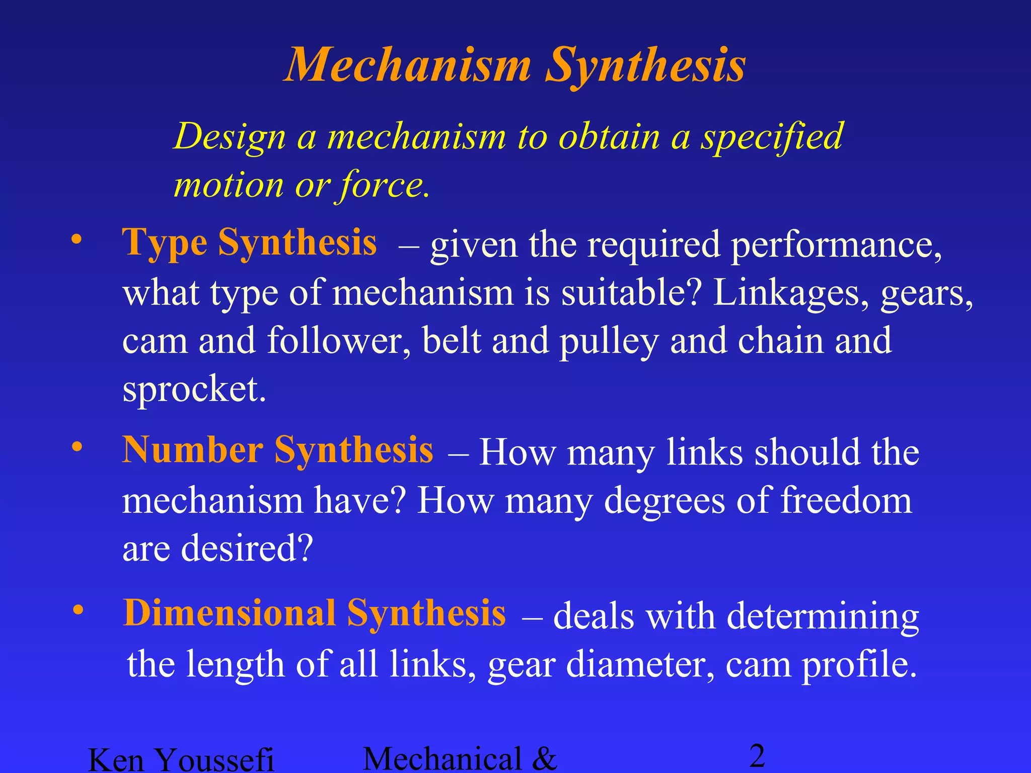
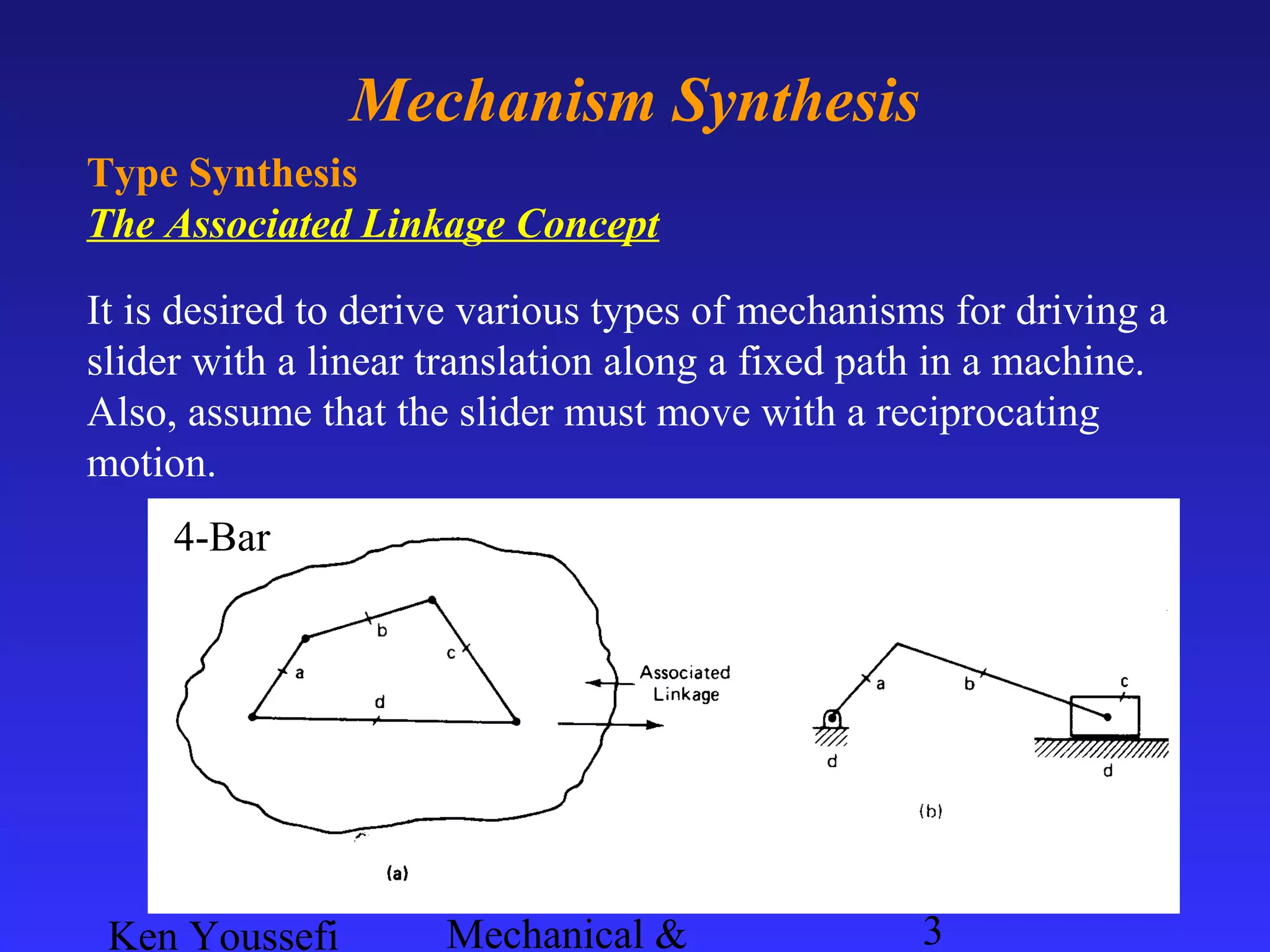
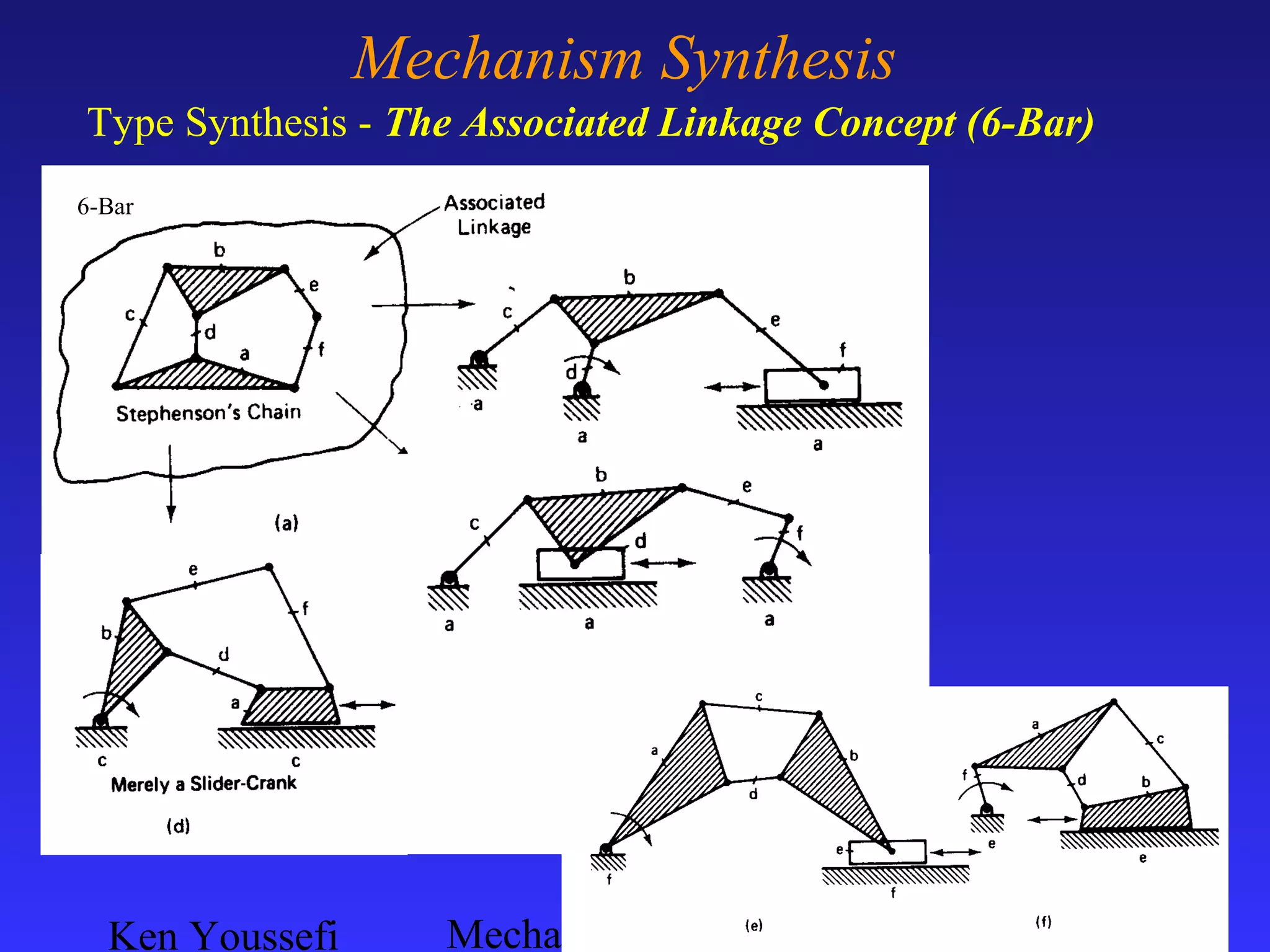
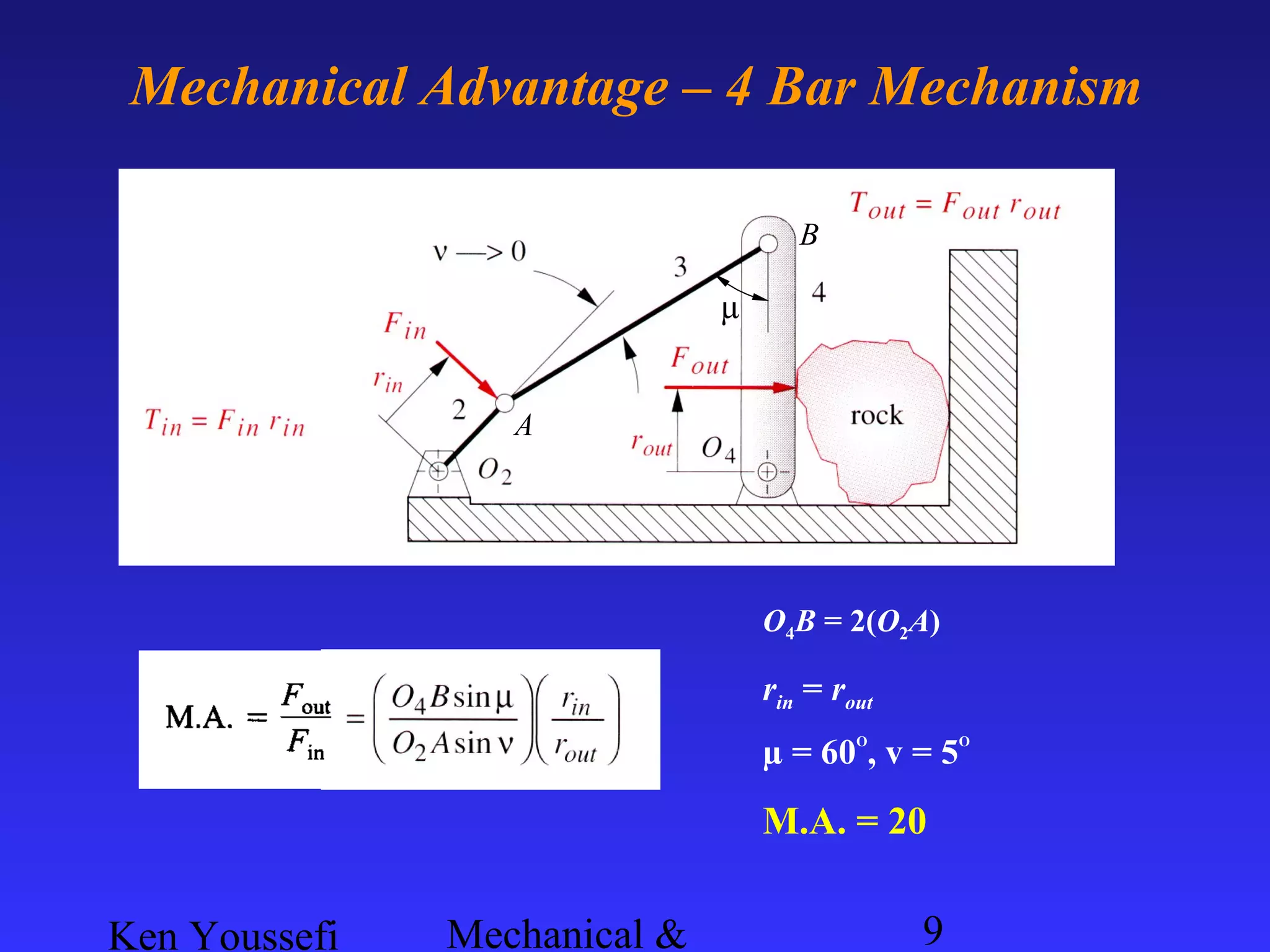
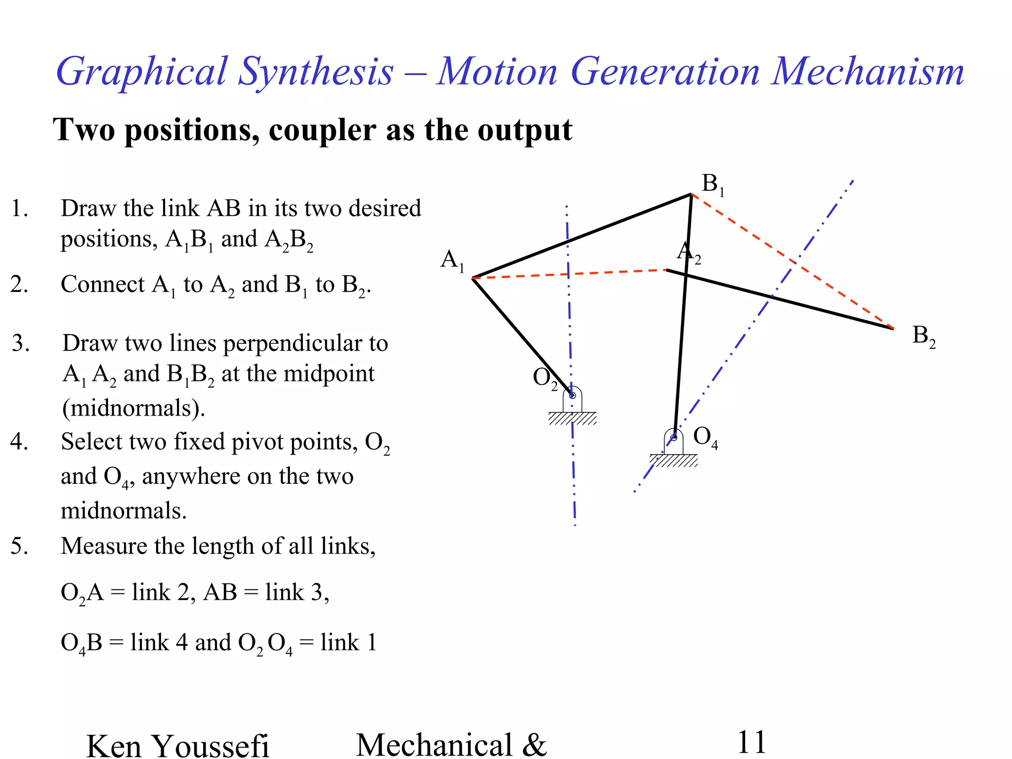
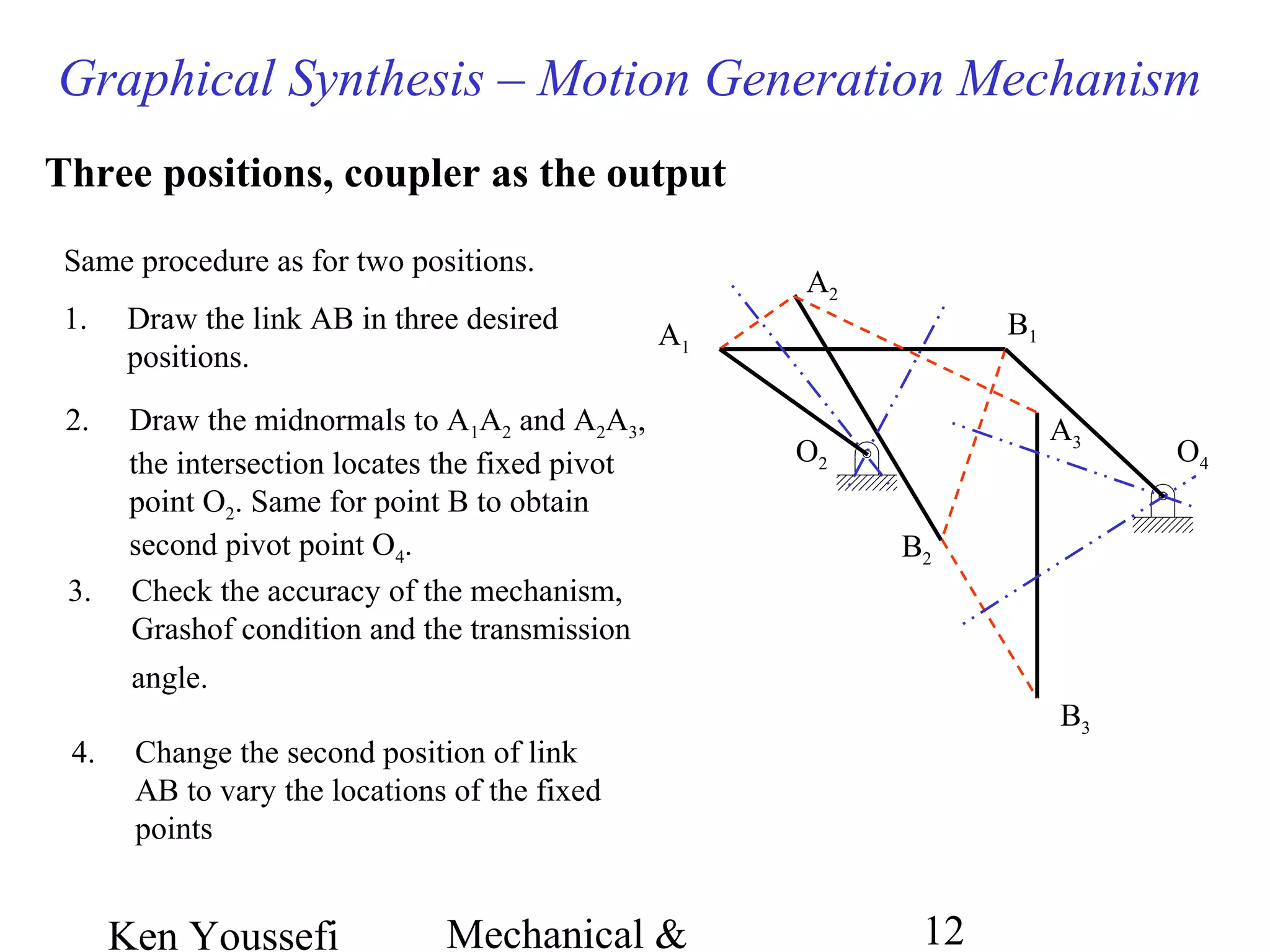
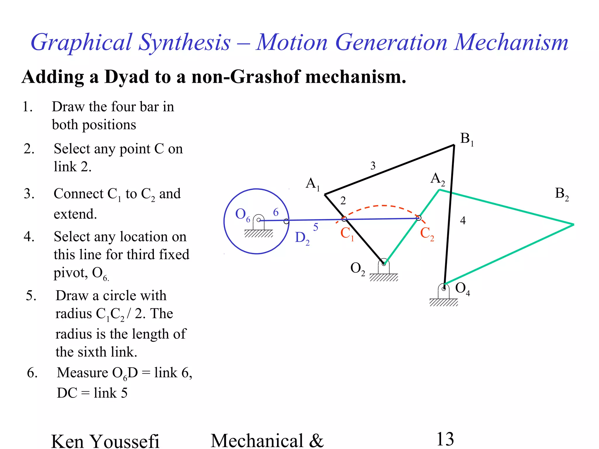
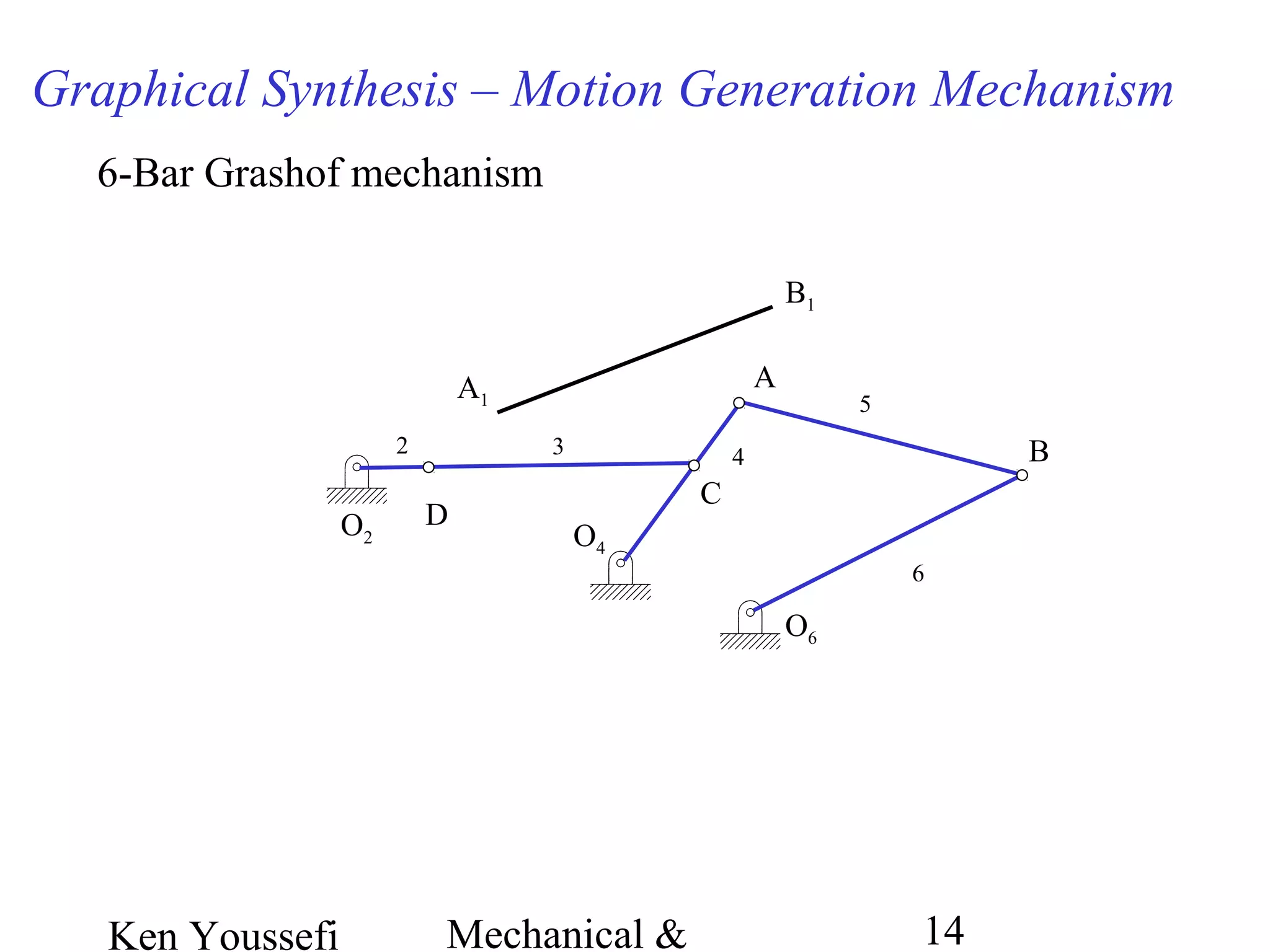
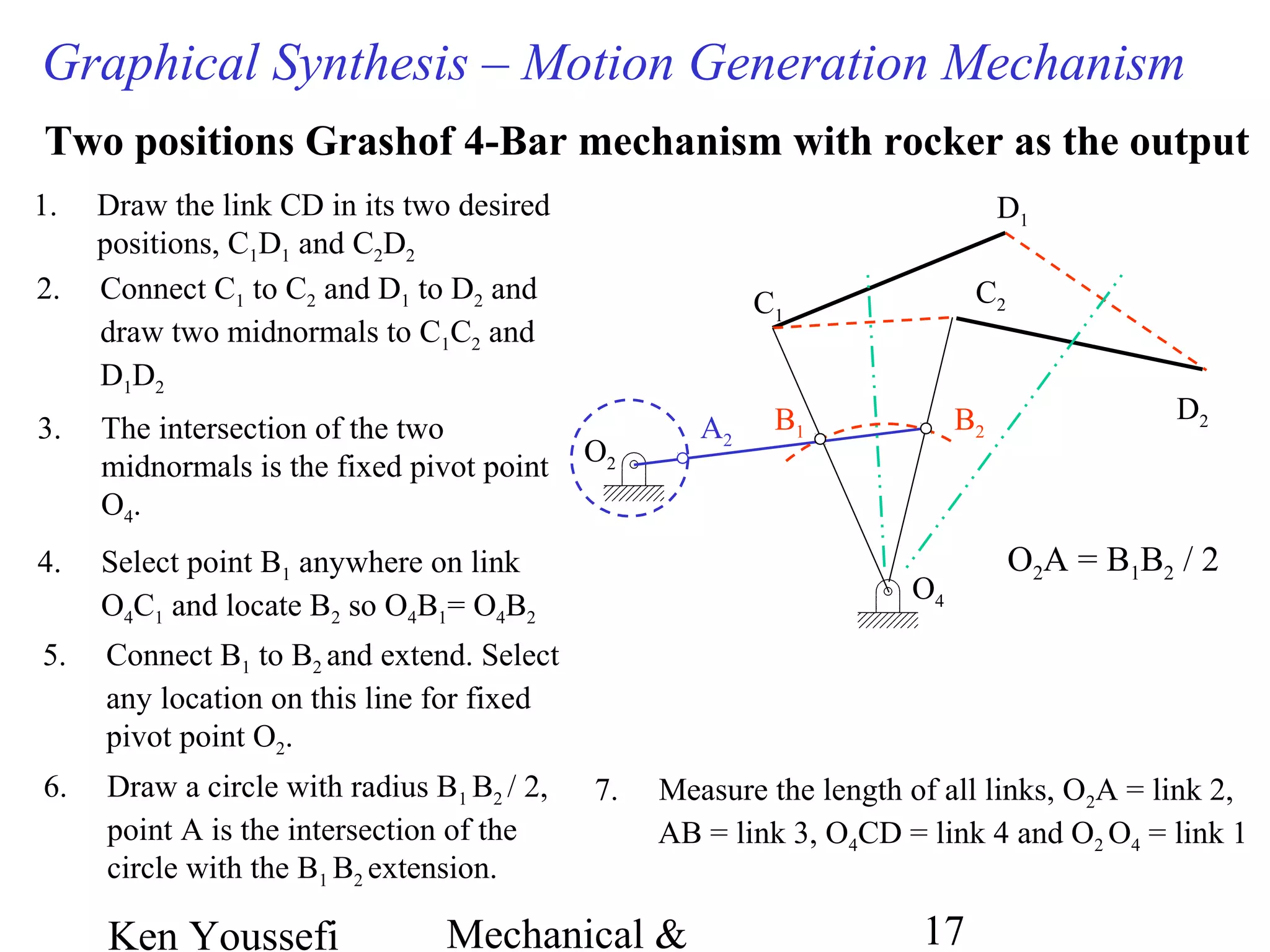
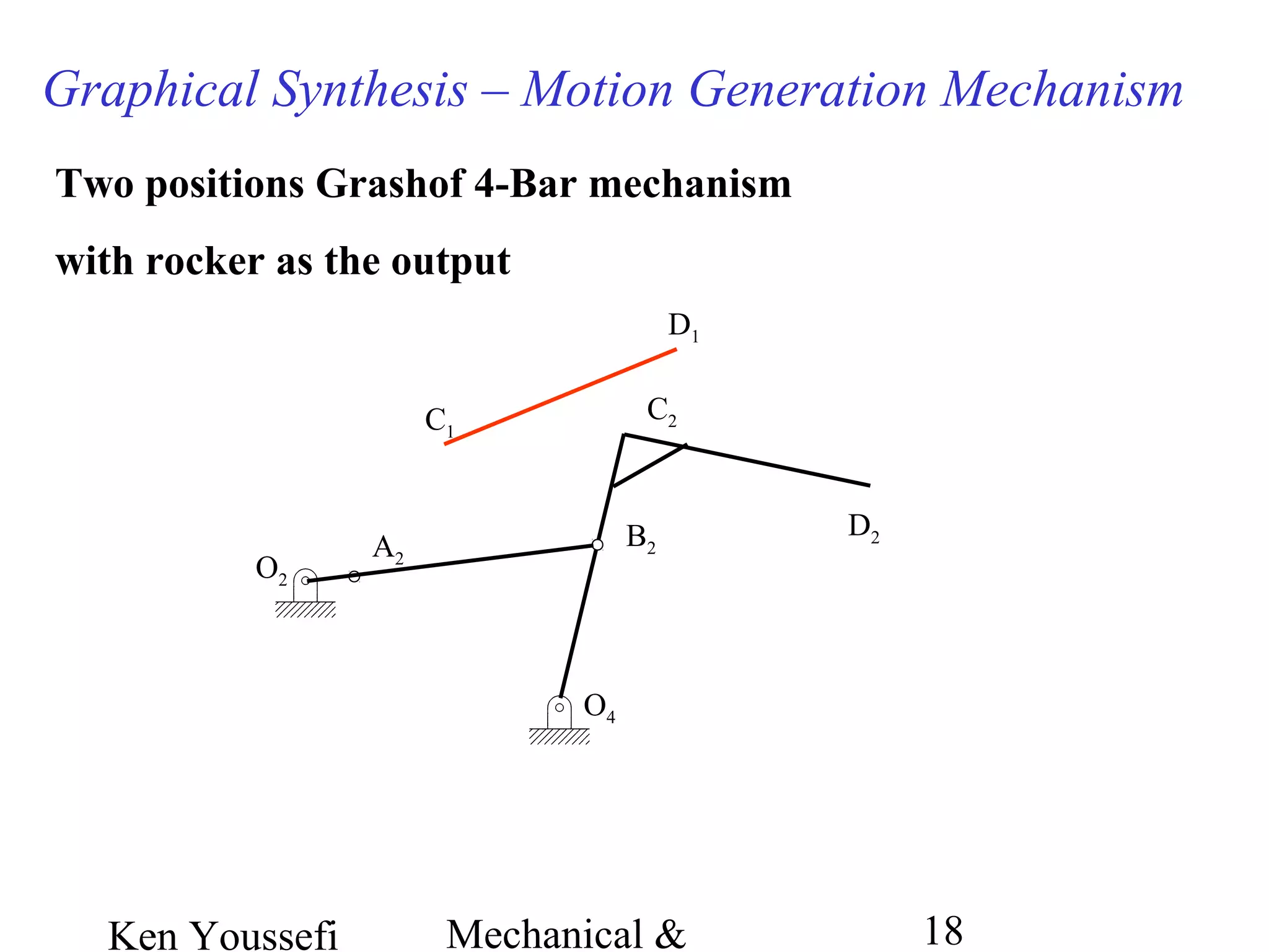
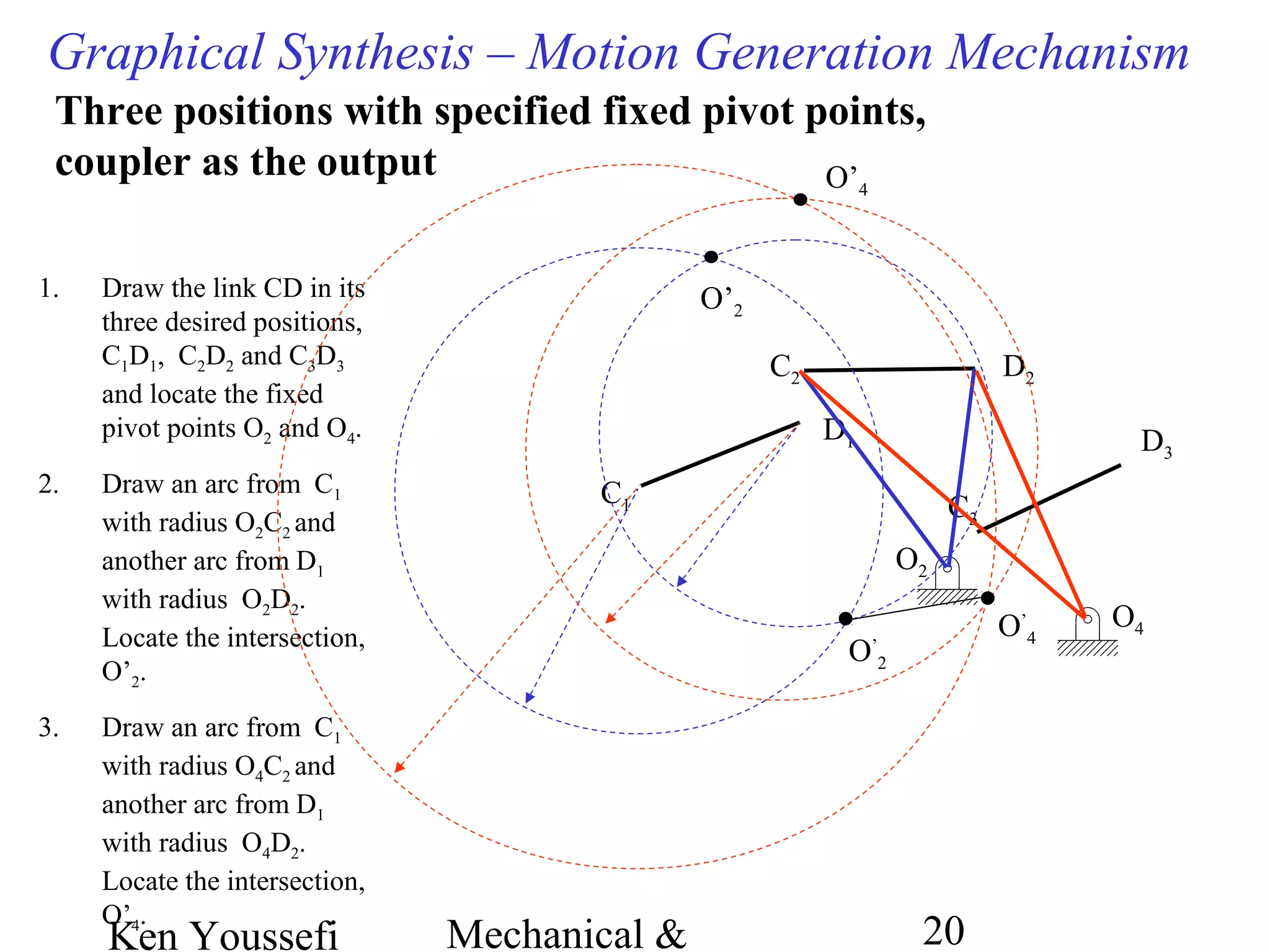
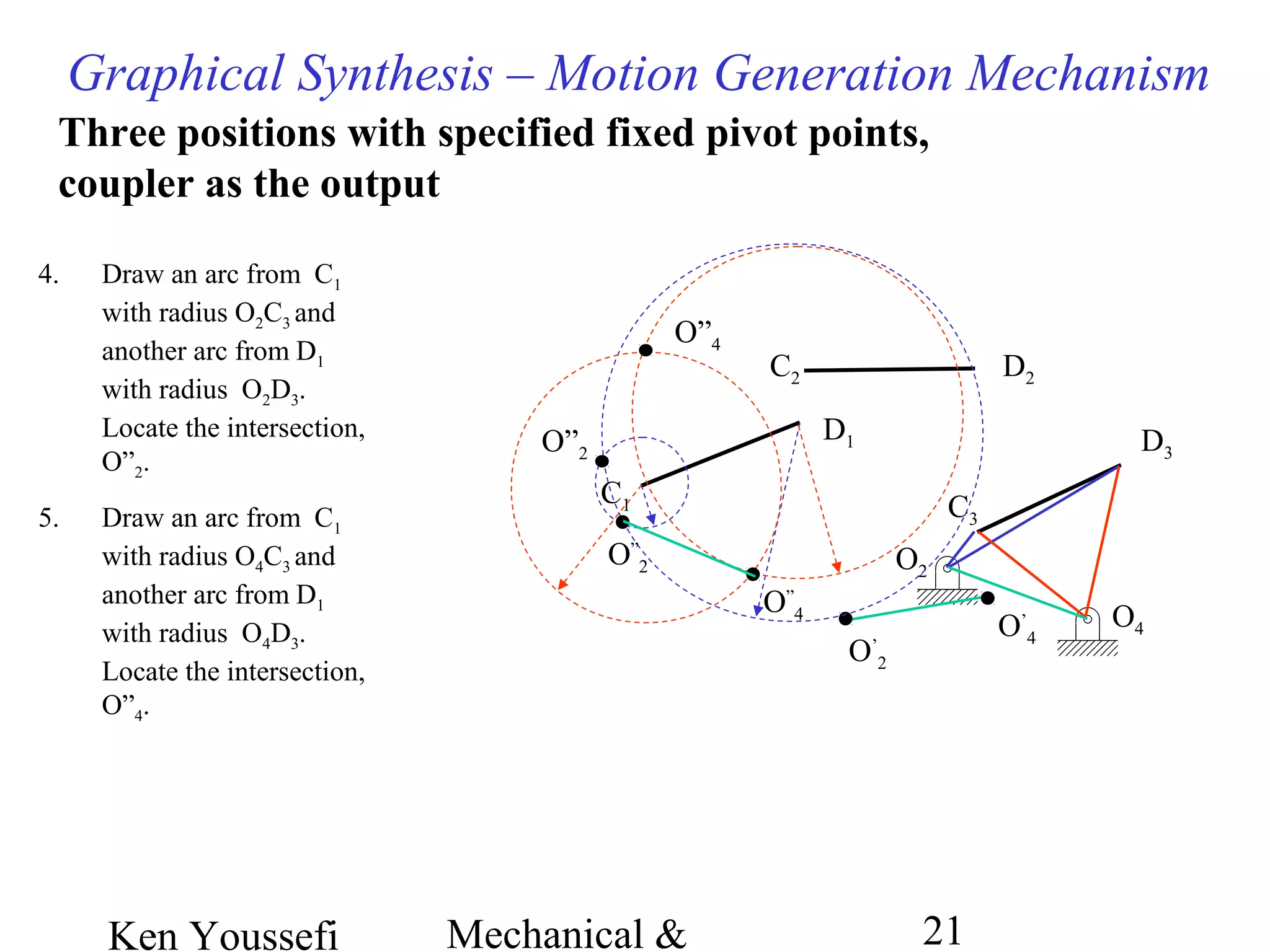
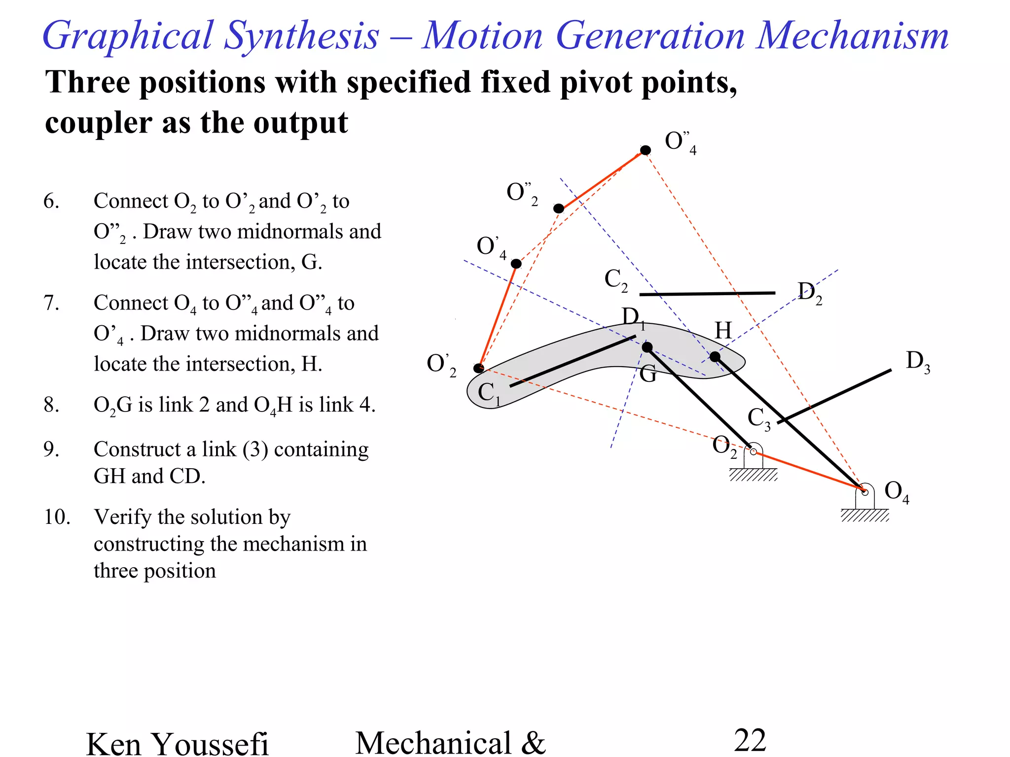
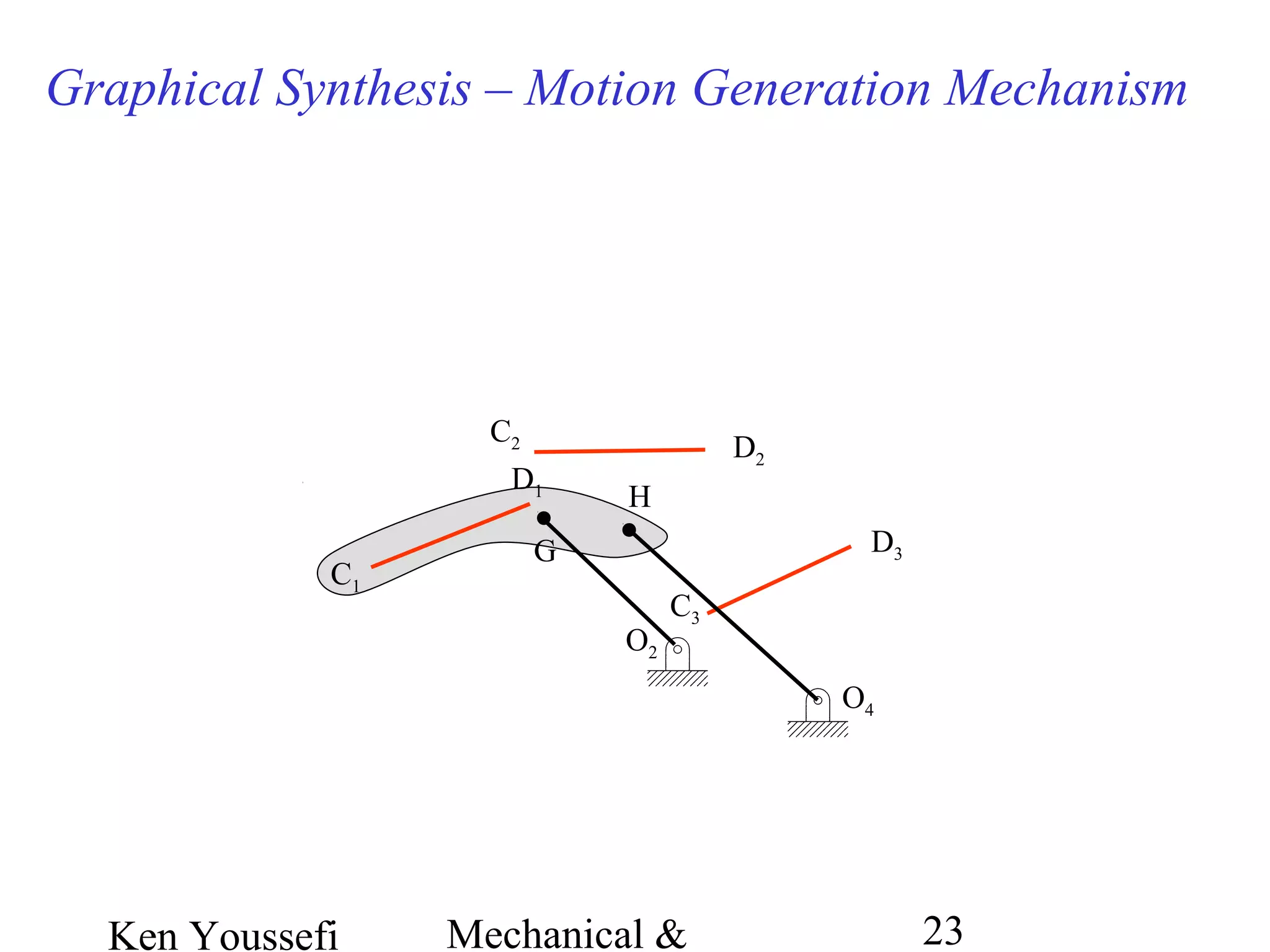
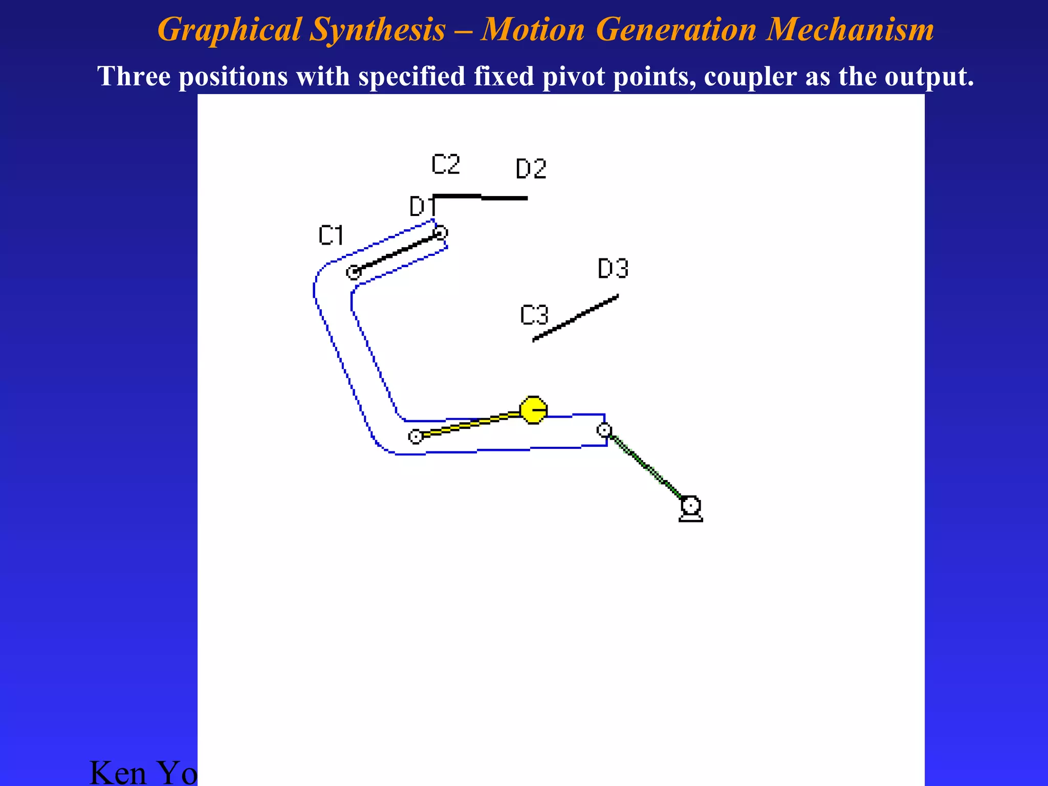
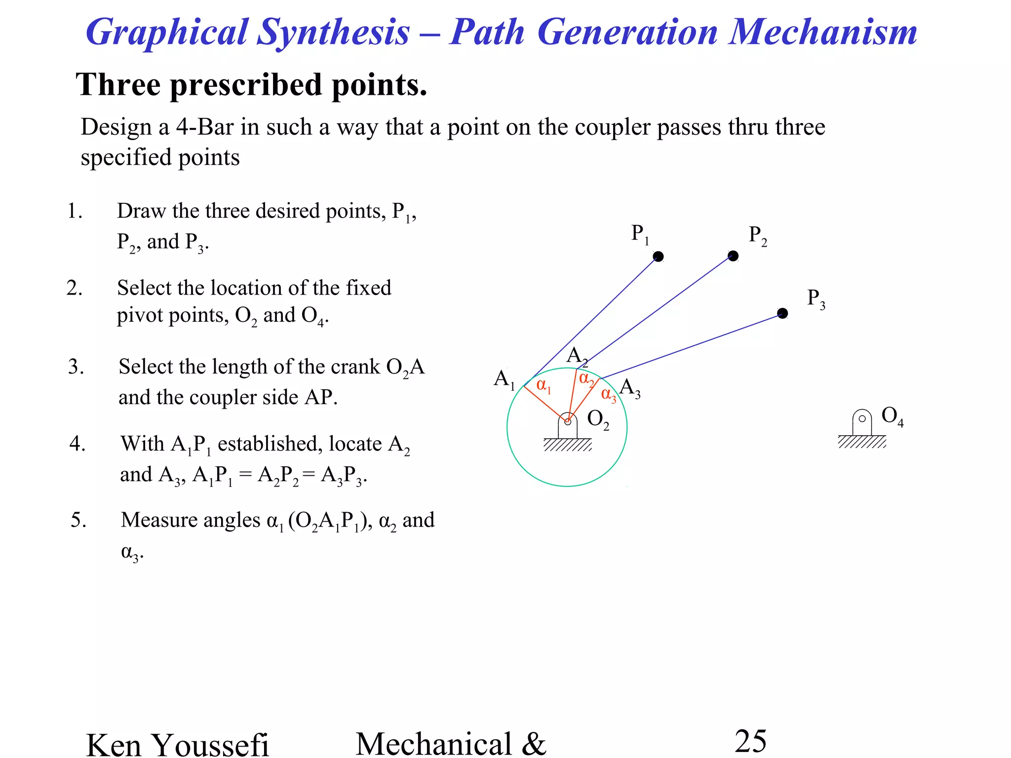
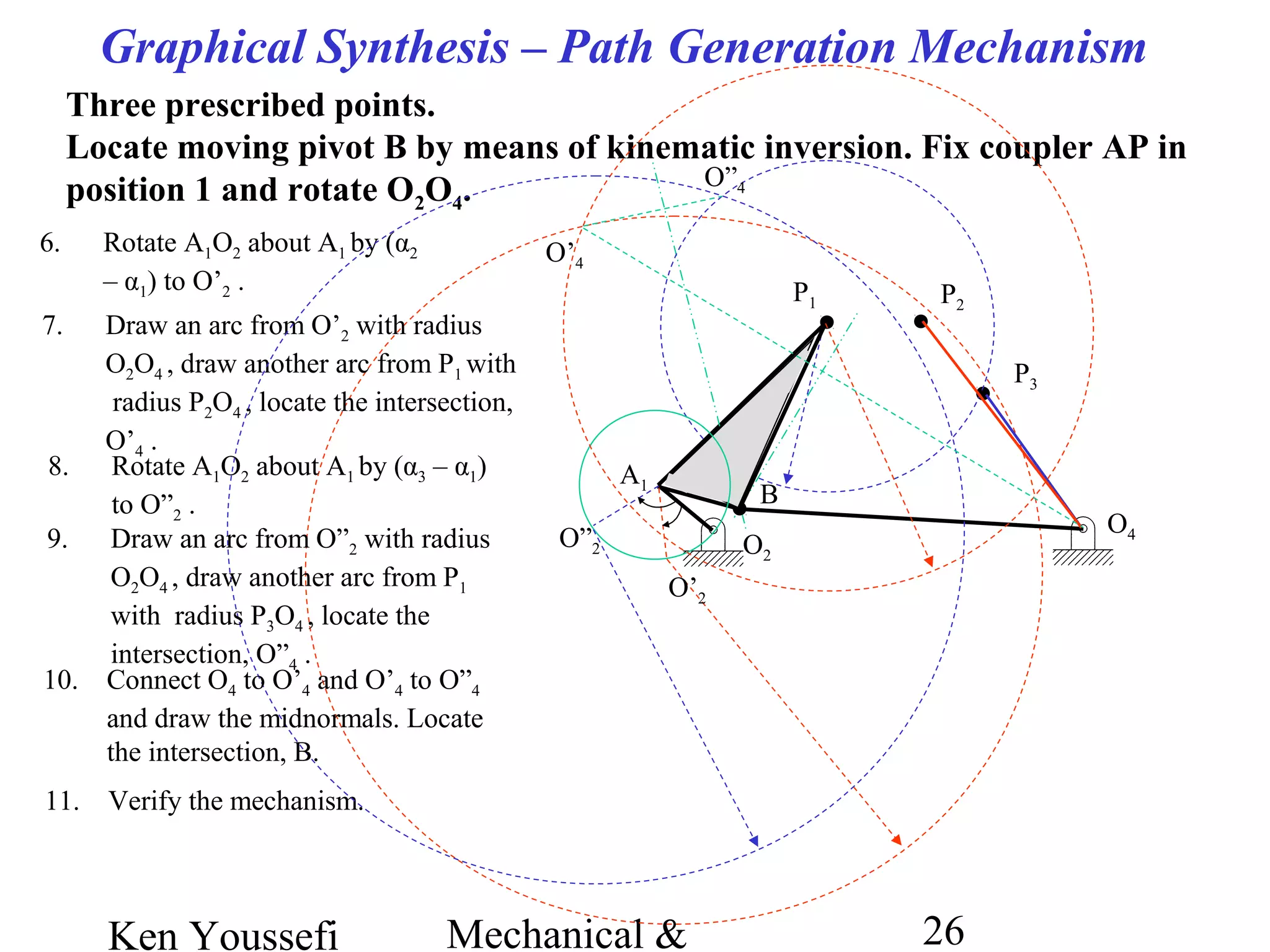
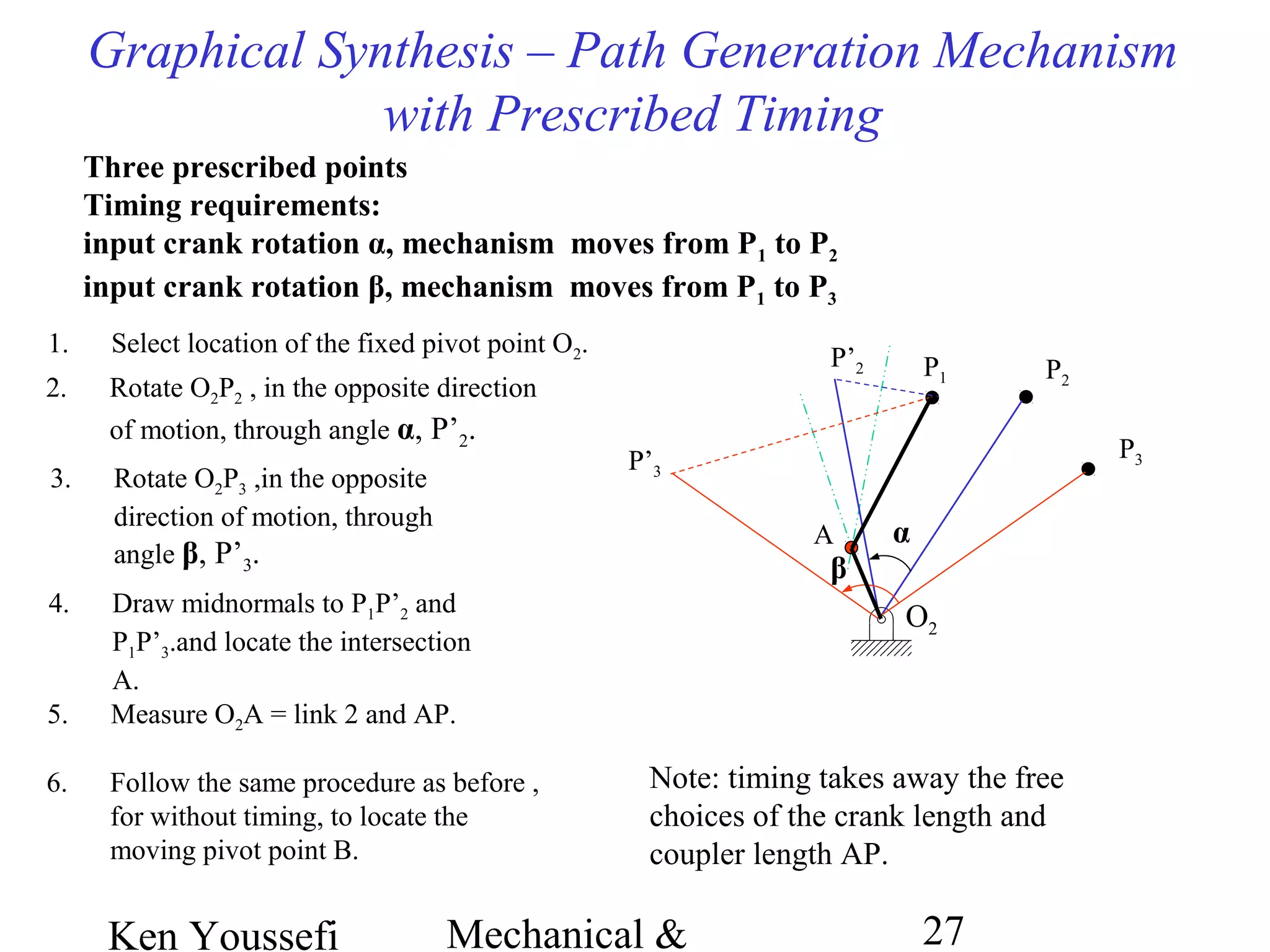
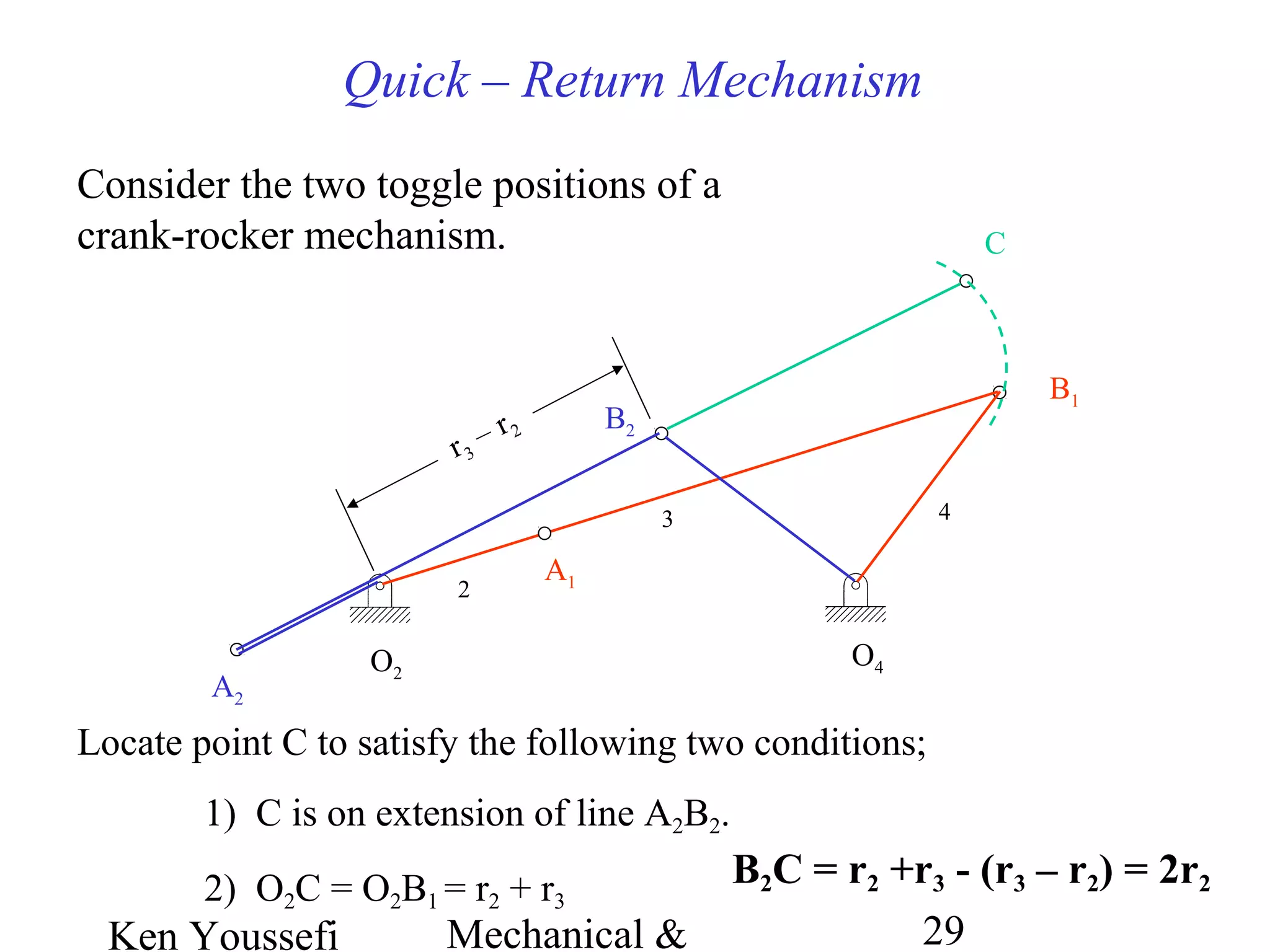
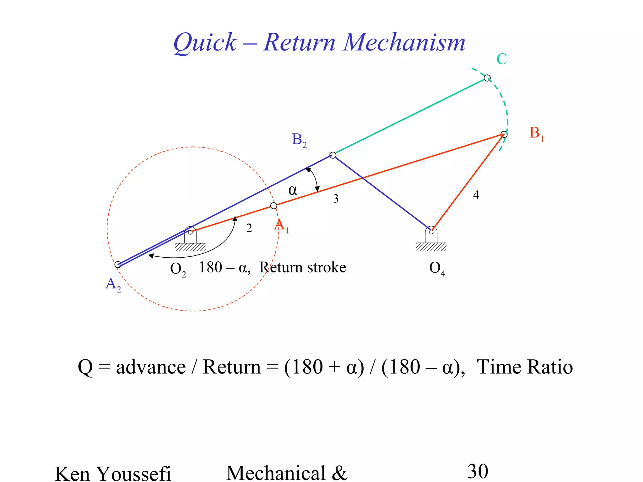
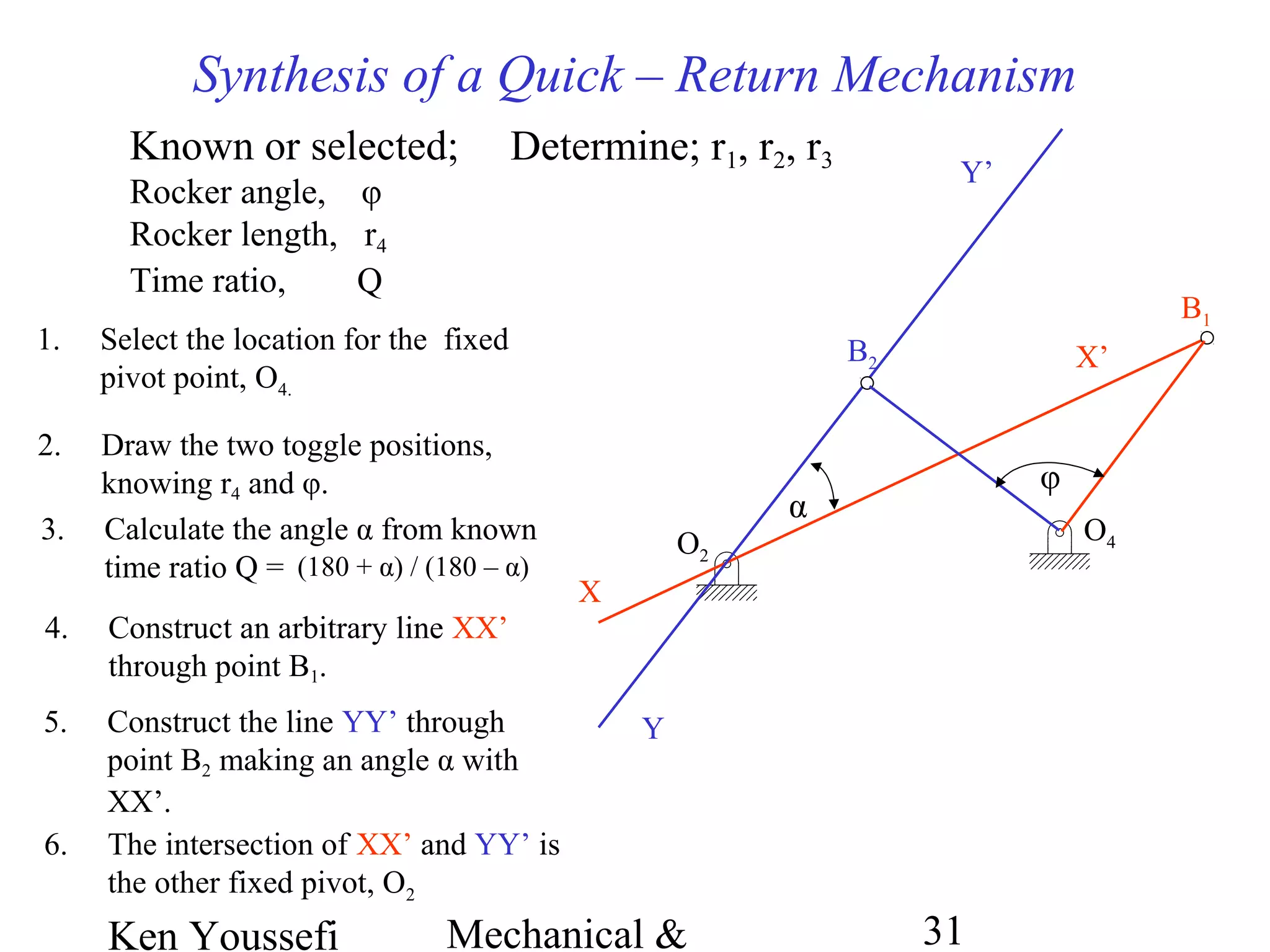
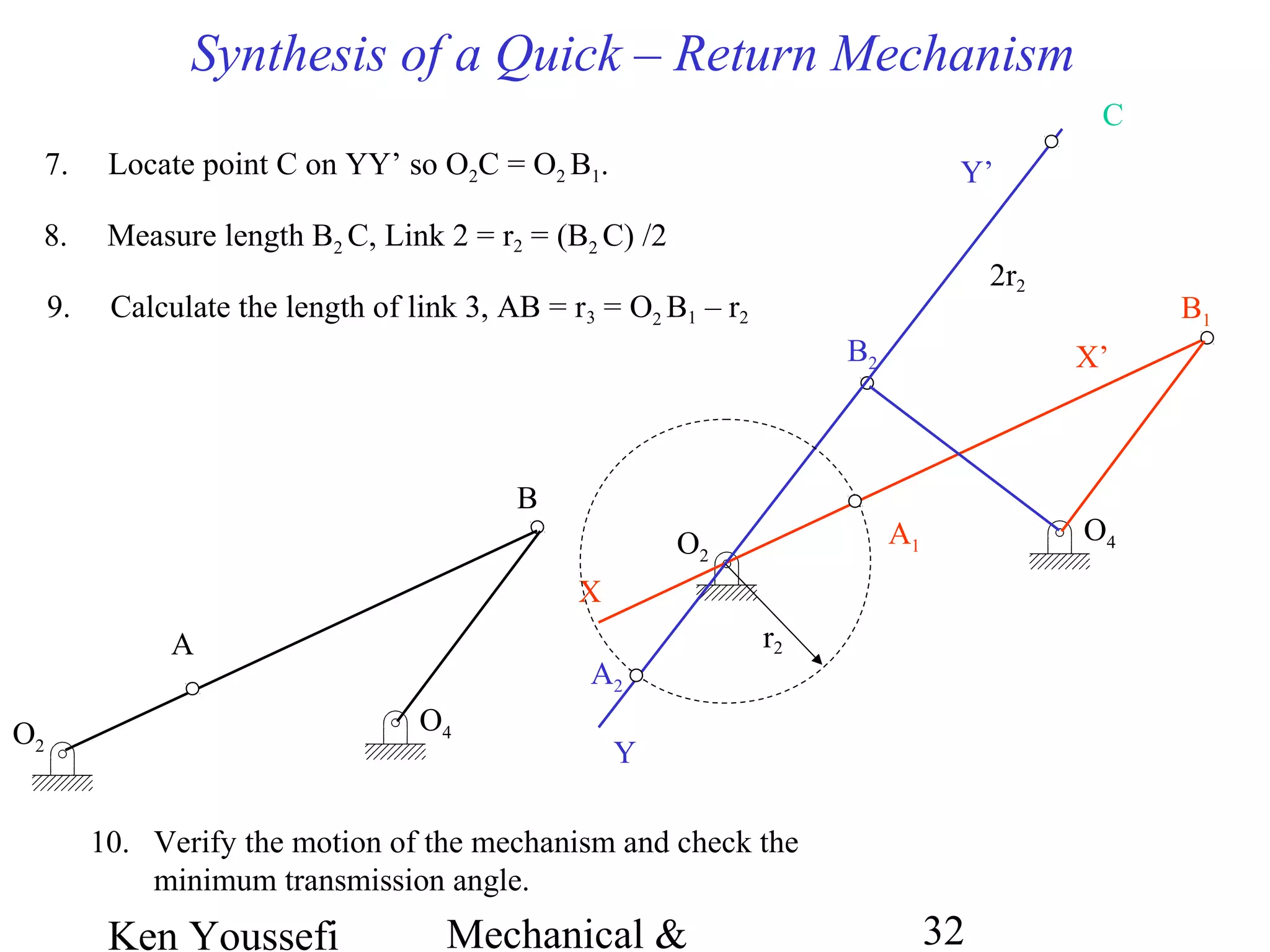
SlideShare a Scribd company logo
Ken Youssefi Mechanical & 1
Mechanism Design
Graphical Method
Ken Youssefi Mechanical & 2
• Dimensional Synthesis
Mechanism Synthesis
Design a mechanism to obtain a specified
motion or force.
– How many links should the
mechanism have? How many degrees of freedom
are desired?
• Number Synthesis
– given the required performance,
what type of mechanism is suitable? Linkages, gears,
cam and follower, belt and pulley and chain and
sprocket.
• Type Synthesis
– deals with determining
the length of all links, gear diameter, cam profile.
Ken Youssefi Mechanical & 3
Mechanism Synthesis
Type Synthesis
The Associated Linkage Concept
It is desired to derive various types of mechanisms for driving a
slider with a linear translation along a fixed path in a machine.
Also, assume that the slider must move with a reciprocating
motion.
4-Bar
Ken Youssefi Mechanical & 4
Mechanism Synthesis
Type Synthesis - The Associated Linkage Concept (6-Bar)
6-Bar
Ken Youssefi Mechanical & 5
Limiting Conditions – 4 Bar Mechanism
Toggle positions of a crank-rocker mechanism. Links 2 and 3
become collinear.
Ken Youssefi Mechanical & 6
Transmission Angle – 4 Bar Mechanism
The angle between link 3 and link 4 is
defined as the transmission angle
T4 = F34sin(µ) x (O4D)
Ken Youssefi Mechanical & 7
Minimum Transmission Angle – 4 Bar Mechanism
Minimum transmission angle occurs when link 2 (crank) becomes
collinear with link 1 (ground link)
The minimum transmission angle should be greater than 40
o
to avoid
locking or jamming the mechanism
µ
Min. transmission
angle
Max. transmission
angle
Ken Youssefi Mechanical & 8
Mechanical Advantage – 4 Bar Mechanism
Ken Youssefi Mechanical & 9
Mechanical Advantage – 4 Bar Mechanism
O4B = 2(O2A)
rin = rout
µ = 60O
, v = 5O
M.A. = 20
µ
A
B
Ken Youssefi Mechanical & 10
Mechanism Synthesis
Dimensional Synthesis
Graphical Methods – provide the designer with
a quick straightforward method but parameters
cannot easily be manipulated to create new
solutions.
– this approach is suitable
for automatic computation. Once a mechanism is
modeled and coded for computer, parameters are
easily manipulated to create new designs.
Analytical Methods
Ken Youssefi Mechanical & 11
O2
O44. Select two fixed pivot points, O2
and O4, anywhere on the two
midnormals.
Graphical Synthesis – Motion Generation Mechanism
Two positions, coupler as the output
A1
A2
B1
B2
1. Draw the link AB in its two desired
positions, A1B1 and A2B2
5. Measure the length of all links,
O2A = link 2, AB = link 3,
O4B = link 4 and O2 O4 = link 1
2. Connect A1 to A2 and B1 to B2.
3. Draw two lines perpendicular to
A1 A2 and B1B2 at the midpoint
(midnormals).
Ken Youssefi Mechanical & 12
O4O2
Graphical Synthesis – Motion Generation Mechanism
Three positions, coupler as the output
A1
A2
A3
B1
B2
B3
Same procedure as for two positions.
1. Draw the link AB in three desired
positions.
2. Draw the midnormals to A1A2 and A2A3,
the intersection locates the fixed pivot
point O2. Same for point B to obtain
second pivot point O4.
3. Check the accuracy of the mechanism,
Grashof condition and the transmission
angle.
4. Change the second position of link
AB to vary the locations of the fixed
points
Ken Youssefi Mechanical & 13
O6
4. Select any location on
this line for third fixed
pivot, O6.
D2
5. Draw a circle with
radius C1C2 / 2. The
radius is the length of
the sixth link.
Graphical Synthesis – Motion Generation Mechanism
Adding a Dyad to a non-Grashof mechanism.
A1
A2
B1
B2
O2
O4
2
3
4
1. Draw the four bar in
both positions
C1 C2
2. Select any point C on
link 2.
3. Connect C1 to C2 and
extend.
5
6
6. Measure O6D = link 6,
DC = link 5
Ken Youssefi Mechanical & 14
Graphical Synthesis – Motion Generation Mechanism
A1
A
B1
O4
O6
C
DO2
B32 4
5
6
6-Bar Grashof mechanism
Ken Youssefi Mechanical & 15
Three Position, 6-Bar Grashof ,Motion Generation Mechanism
Ken Youssefi Mechanical & 16
Three Position, 6-Bar Grashof ,Motion Generation Mechanism
Ken Youssefi Mechanical & 17
Graphical Synthesis – Motion Generation Mechanism
Two positions Grashof 4-Bar mechanism with rocker as the output
D1
C1
C2
D2
O2
5. Connect B1 to B2 and extend. Select
any location on this line for fixed
pivot point O2.
O2A = B1B2 / 2
7. Measure the length of all links, O2A = link 2,
AB = link 3, O4CD = link 4 and O2 O4 = link 1
1. Draw the link CD in its two desired
positions, C1D1 and C2D2
2. Connect C1 to C2 and D1 to D2 and
draw two midnormals to C1C2 and
D1D2
O4
3. The intersection of the two
midnormals is the fixed pivot point
O4.
B1 B2
4. Select point B1 anywhere on link
O4C1 and locate B2 so O4B1= O4B2
A2
6. Draw a circle with radius B1 B2 / 2,
point A is the intersection of the
circle with the B1 B2 extension.
Ken Youssefi Mechanical & 18
Graphical Synthesis – Motion Generation Mechanism
Two positions Grashof 4-Bar mechanism
with rocker as the output
D1
C1
C2
A2
O4
O2
B2
D2
Ken Youssefi Mechanical & 19
Two Position, 4-Bar Grashof Motion Generation Mechanism
Ken Youssefi Mechanical & 20
Graphical Synthesis – Motion Generation Mechanism
Three positions with specified fixed pivot points,
coupler as the output
C1
D1
C2
C3
D2
D3
O4
O2
1. Draw the link CD in its
three desired positions,
C1D1, C2D2 and C3D3
and locate the fixed
pivot points O2 and O4.
2. Draw an arc from C1
with radius O2C2 and
another arc from D1
with radius O2D2.
Locate the intersection,
O’2.
3. Draw an arc from C1
with radius O4C2 and
another arc from D1
with radius O4D2.
Locate the intersection,
O’4.
O’
4
O’
2
O’2
O’4
Ken Youssefi Mechanical & 21
Graphical Synthesis – Motion Generation Mechanism
C1
D1
C2
C3
D2
D3
O4
O2
O’
2
O’
4
Three positions with specified fixed pivot points,
coupler as the output
4. Draw an arc from C1
with radius O2C3 and
another arc from D1
with radius O2D3.
Locate the intersection,
O”2.
5. Draw an arc from C1
with radius O4C3 and
another arc from D1
with radius O4D3.
Locate the intersection,
O”4.
O”
2
O”
4
O”2
O”4
Ken Youssefi Mechanical & 22
C1
D1
C2
C3
D2
O4
O2
O”
2
O”
4
O’
2
O’
4
G
H
Graphical Synthesis – Motion Generation Mechanism
Three positions with specified fixed pivot points,
coupler as the output
D3
6. Connect O2 to O’2 and O’2 to
O”2 . Draw two midnormals and
locate the intersection, G.
7. Connect O4 to O”4 and O”4 to
O’4 . Draw two midnormals and
locate the intersection, H.
8. O2G is link 2 and O4H is link 4.
9. Construct a link (3) containing
GH and CD.
10. Verify the solution by
constructing the mechanism in
three position
Ken Youssefi Mechanical & 23
Graphical Synthesis – Motion Generation Mechanism
C1
D1
C2
C3
D2
O4
O2
G
H
D3
Ken Youssefi Mechanical & 24
Graphical Synthesis – Motion Generation Mechanism
Three positions with specified fixed pivot points, coupler as the output.
Ken Youssefi Mechanical & 25
O4O2
2. Select the location of the fixed
pivot points, O2 and O4.
Graphical Synthesis – Path Generation Mechanism
Three prescribed points.
5. Measure angles α1 (O2A1P1), α2 and
α3.
α1
α2
α3
P1 P2
P3
1. Draw the three desired points, P1,
P2, and P3.
A1
3. Select the length of the crank O2A
and the coupler side AP. A3
A2
4. With A1P1 established, locate A2
and A3, A1P1 = A2P2 = A3P3.
Design a 4-Bar in such a way that a point on the coupler passes thru three
specified points
Ken Youssefi Mechanical & 26
Graphical Synthesis – Path Generation Mechanism
Three prescribed points.
Locate moving pivot B by means of kinematic inversion. Fix coupler AP in
position 1 and rotate O2O4.
O4
O2
P1 P2
P3
A1
11. Verify the mechanism.
B
O”4
O’2
6. Rotate A1O2 about A1 by (α2
– α1) to O’2 .
O’4
7. Draw an arc from O’2 with radius
O2O4 , draw another arc from P1 with
radius P2O4 , locate the intersection,
O’4 .
O”2
8. Rotate A1O2 about A1 by (α3 – α1)
to O”2 .
9. Draw an arc from O”2 with radius
O2O4 , draw another arc from P1
with radius P3O4 , locate the
intersection, O”4 .
10. Connect O4 to O’4 and O’4 to O”4
and draw the midnormals. Locate
the intersection, B.
Ken Youssefi Mechanical & 27
O2
1. Select location of the fixed pivot point O2.
Graphical Synthesis – Path Generation Mechanism
with Prescribed Timing
Three prescribed points
Timing requirements:
input crank rotation α, mechanism moves from P1 to P2
input crank rotation β, mechanism moves from P1 to P3
P1 P2
P3
6. Follow the same procedure as before ,
for without timing, to locate the
moving pivot point B.
A
Note: timing takes away the free
choices of the crank length and
coupler length AP.
P’2
α
2. Rotate O2P2 , in the opposite direction
of motion, through angle α, P’2.
P’3
β
3. Rotate O2P3 ,in the opposite
direction of motion, through
angle β, P’3.
4. Draw midnormals to P1P’2 and
P1P’3.and locate the intersection
A.
5. Measure O2A = link 2 and AP.
Ken Youssefi Mechanical & 28
Graphical Synthesis; Quick – Return Mechanism
Q = time of advance stroke / time of return stroke
Q > 1 quick-return mechanism
Advance stroke – mechanism operates under the load.
Return stroke – mechanism operates under no load.
4-Bar crank-Rocker mechanism
Ken Youssefi Mechanical & 29
Quick – Return Mechanism
Consider the two toggle positions of a
crank-rocker mechanism.
O4O2
B1
2
3 4
A1
B2
A2
C
Locate point C to satisfy the following two conditions;
1) C is on extension of line A2B2.
2) O2C = O2B1 = r2 + r3
B2C = r2 +r3 - (r3 – r2) = 2r2
r3
– r2
Ken Youssefi Mechanical & 30
Quick – Return Mechanism
O4O2
B1
2
3 4
A1
B2
A2
C
α
180 – α, Return stroke
Q = advance / Return = (180 + α) / (180 – α), Time Ratio
Ken Youssefi Mechanical & 31
Synthesis of a Quick – Return Mechanism
Known or selected;
Rocker angle, φ
Rocker length, r4
Time ratio, Q
Determine; r1, r2, r3
O4
1. Select the location for the fixed
pivot point, O4.
O2
6. The intersection of XX’ and YY’ is
the other fixed pivot, O2
X
4. Construct an arbitrary line XX’
through point B1.
X’
5. Construct the line YY’ through
point B2 making an angle α with
XX’.
Y
Y’
α
2. Draw the two toggle positions,
knowing r4 and φ.
B1
B2
φ
3. Calculate the angle α from known
time ratio Q = (180 + α) / (180 – α)
Ken Youssefi Mechanical & 32
Synthesis of a Quick – Return Mechanism
O2
X
Y’
O4
X’
Y
B1
B2
7. Locate point C on YY’ so O2C = O2 B1.
C
9. Calculate the length of link 3, AB = r3 = O2 B1 – r2
8. Measure length B2 C, Link 2 = r2 = (B2 C) /2
2r2
A1
r2
A2
A
O4O2
B
10. Verify the motion of the mechanism and check the
minimum transmission angle.

More Related Content

What's hot

Gear finishing processes
Gear finishing processesGear finishing processes
Gear finishing processes
Mechbytes
 
Manufacturing Technology-II Unit 5
Manufacturing Technology-II Unit 5Manufacturing Technology-II Unit 5
Manufacturing Technology-II Unit 5
Ravi Sankar
 
Solutions Manual for machine design by khurmi and Gupta
Solutions Manual for machine design by khurmi and GuptaSolutions Manual for machine design by khurmi and Gupta
Solutions Manual for machine design by khurmi and Gupta
Adnan Aslam
 
CAM AND FOLLOWER
CAM AND FOLLOWERCAM AND FOLLOWER
CAM AND FOLLOWER
Kunj Thummar
 
Velocity and acceleration of mechanisms
Velocity and acceleration of mechanismsVelocity and acceleration of mechanisms
Velocity and acceleration of mechanisms
Hareesha N Gowda, Dayananda Sagar College of Engg, Bangalore
 
Tolerances and allowances
Tolerances and allowancesTolerances and allowances
Tolerances and allowances
Gulfam Hussain
 
Machining Process
Machining ProcessMachining Process
Machining Process
Kunj Soni
 
Cnc lab manual
Cnc lab manualCnc lab manual
Cnc lab manual
SubhasgoudPatil
 
Quick return mechanism
Quick return mechanismQuick return mechanism
Quick return mechanism
Saif al-din ali
 
Kinematic Synthesis
Kinematic SynthesisKinematic Synthesis
Kinematic Synthesis
Yatin Singh
 
Unit 2.3 Design of Coupling
Unit 2.3 Design of CouplingUnit 2.3 Design of Coupling
Unit 2.3 Design of Coupling
Yugal Kishor Sahu
 
1.4 law of gearing
1.4 law of gearing1.4 law of gearing
1.4 law of gearing
Kiran Wakchaure
 
CAM AND FOLLOWER
CAM AND FOLLOWERCAM AND FOLLOWER
CAM AND FOLLOWER
AJAY SAVITA
 
STEP TURNING AND TAPER TURNING ON LATHE
STEP TURNING AND TAPER TURNING ON LATHESTEP TURNING AND TAPER TURNING ON LATHE
STEP TURNING AND TAPER TURNING ON LATHE
Salman Jailani
 
Whitworth Quick Return Mechanism
Whitworth Quick Return MechanismWhitworth Quick Return Mechanism
Whitworth Quick Return Mechanism
Harshit Sankhla
 
Instantaneous center method
Instantaneous center methodInstantaneous center method
Instantaneous center method
Rohit Singla
 
Velocity & acceleration diagrams
Velocity & acceleration diagramsVelocity & acceleration diagrams
Velocity & acceleration diagrams
sherin_ginige
 
4.8 cam jump phenomenon
4.8 cam jump phenomenon4.8 cam jump phenomenon
4.8 cam jump phenomenon
Kiran Wakchaure
 
7 steering mechanisms
7 steering mechanisms7 steering mechanisms
7 steering mechanisms
shaikusmanshag
 
knuckle Joint 2D drawing AutoCAD 2019
knuckle Joint 2D drawing AutoCAD 2019knuckle Joint 2D drawing AutoCAD 2019
knuckle Joint 2D drawing AutoCAD 2019
university of Sarghodha Lahore campus
 

What's hot (20)

Gear finishing processes
Gear finishing processesGear finishing processes
Gear finishing processes
 
Manufacturing Technology-II Unit 5
Manufacturing Technology-II Unit 5Manufacturing Technology-II Unit 5
Manufacturing Technology-II Unit 5
 
Solutions Manual for machine design by khurmi and Gupta
Solutions Manual for machine design by khurmi and GuptaSolutions Manual for machine design by khurmi and Gupta
Solutions Manual for machine design by khurmi and Gupta
 
CAM AND FOLLOWER
CAM AND FOLLOWERCAM AND FOLLOWER
CAM AND FOLLOWER
 
Velocity and acceleration of mechanisms
Velocity and acceleration of mechanismsVelocity and acceleration of mechanisms
Velocity and acceleration of mechanisms
 
Tolerances and allowances
Tolerances and allowancesTolerances and allowances
Tolerances and allowances
 
Machining Process
Machining ProcessMachining Process
Machining Process
 
Cnc lab manual
Cnc lab manualCnc lab manual
Cnc lab manual
 
Quick return mechanism
Quick return mechanismQuick return mechanism
Quick return mechanism
 
Kinematic Synthesis
Kinematic SynthesisKinematic Synthesis
Kinematic Synthesis
 
Unit 2.3 Design of Coupling
Unit 2.3 Design of CouplingUnit 2.3 Design of Coupling
Unit 2.3 Design of Coupling
 
1.4 law of gearing
1.4 law of gearing1.4 law of gearing
1.4 law of gearing
 
CAM AND FOLLOWER
CAM AND FOLLOWERCAM AND FOLLOWER
CAM AND FOLLOWER
 
STEP TURNING AND TAPER TURNING ON LATHE
STEP TURNING AND TAPER TURNING ON LATHESTEP TURNING AND TAPER TURNING ON LATHE
STEP TURNING AND TAPER TURNING ON LATHE
 
Whitworth Quick Return Mechanism
Whitworth Quick Return MechanismWhitworth Quick Return Mechanism
Whitworth Quick Return Mechanism
 
Instantaneous center method
Instantaneous center methodInstantaneous center method
Instantaneous center method
 
Velocity & acceleration diagrams
Velocity & acceleration diagramsVelocity & acceleration diagrams
Velocity & acceleration diagrams
 
4.8 cam jump phenomenon
4.8 cam jump phenomenon4.8 cam jump phenomenon
4.8 cam jump phenomenon
 
7 steering mechanisms
7 steering mechanisms7 steering mechanisms
7 steering mechanisms
 
knuckle Joint 2D drawing AutoCAD 2019
knuckle Joint 2D drawing AutoCAD 2019knuckle Joint 2D drawing AutoCAD 2019
knuckle Joint 2D drawing AutoCAD 2019
 

Similar to Mechanism synthesis, graphical

sintesis grafica mecanismos
sintesis grafica mecanismossintesis grafica mecanismos
sintesis grafica mecanismos
Mecanismos Ucr
 
Mechanism synthesis, graphical
Mechanism synthesis, graphicalMechanism synthesis, graphical
Mechanism synthesis, graphical
Mecanismos Ucr
 
Curve1- ENGINEERING DRAWING - RGPV,BHOPAL
Curve1- ENGINEERING DRAWING - RGPV,BHOPALCurve1- ENGINEERING DRAWING - RGPV,BHOPAL
Curve1- ENGINEERING DRAWING - RGPV,BHOPAL
Abhishek Kandare
 
Curve1
Curve1Curve1
S5 S6.pdf
S5 S6.pdfS5 S6.pdf
S5 S6.pdf
DrRajalakshmiM
 
solution manual Design of Machinery: An Introduction to the Synthesis and Ana...
solution manual Design of Machinery: An Introduction to the Synthesis and Ana...solution manual Design of Machinery: An Introduction to the Synthesis and Ana...
solution manual Design of Machinery: An Introduction to the Synthesis and Ana...
MichaelLeigh25
 
Instantaneous_centre_Method_of_Velocity_ppt.pptx
Instantaneous_centre_Method_of_Velocity_ppt.pptxInstantaneous_centre_Method_of_Velocity_ppt.pptx
Instantaneous_centre_Method_of_Velocity_ppt.pptx
abhi198876
 
Mechanical Engineering Syllabus Curriculum
Mechanical Engineering Syllabus CurriculumMechanical Engineering Syllabus Curriculum
Mechanical Engineering Syllabus Curriculum
Sreesh P Somarajan
 
Conics Sections.pptx
Conics Sections.pptxConics Sections.pptx
Conics Sections.pptx
Pradeep140613
 
Curve1
Curve1Curve1
Gn3112461257
Gn3112461257Gn3112461257
Gn3112461257
IJERA Editor
 
Engineering Curves
Engineering CurvesEngineering Curves
Engineering Curves
Student
 
Curves2 -ENGINEERING DRAWING - RGPV,BHOPAL
Curves2 -ENGINEERING DRAWING - RGPV,BHOPALCurves2 -ENGINEERING DRAWING - RGPV,BHOPAL
Curves2 -ENGINEERING DRAWING - RGPV,BHOPAL
Abhishek Kandare
 
Fm33980983
Fm33980983Fm33980983
Fm33980983
IJERA Editor
 
ENGINEERING CURVES
ENGINEERING CURVESENGINEERING CURVES
ENGINEERING CURVES
Jitin Pillai
 
Modified EG FULL PORTION PPT 2020 (1).pptx
Modified EG FULL PORTION PPT 2020 (1).pptxModified EG FULL PORTION PPT 2020 (1).pptx
Modified EG FULL PORTION PPT 2020 (1).pptx
Sriharsha203438
 
EG unit 1 - Plane curves
EG unit 1 - Plane curvesEG unit 1 - Plane curves
EG unit 1 - Plane curves
balajijayavel
 
I-_UNIT-_CURVES.pdf
I-_UNIT-_CURVES.pdfI-_UNIT-_CURVES.pdf
I-_UNIT-_CURVES.pdf
OnkarLagshetti
 
Quick return mechanism
Quick return mechanismQuick return mechanism
Quick return mechanism
Saif al-din ali
 
Engineering curve directrix,rectangle method
Engineering curve directrix,rectangle methodEngineering curve directrix,rectangle method
Engineering curve directrix,rectangle method
pratibha60
 

Similar to Mechanism synthesis, graphical (20)

sintesis grafica mecanismos
sintesis grafica mecanismossintesis grafica mecanismos
sintesis grafica mecanismos
 
Mechanism synthesis, graphical
Mechanism synthesis, graphicalMechanism synthesis, graphical
Mechanism synthesis, graphical
 
Curve1- ENGINEERING DRAWING - RGPV,BHOPAL
Curve1- ENGINEERING DRAWING - RGPV,BHOPALCurve1- ENGINEERING DRAWING - RGPV,BHOPAL
Curve1- ENGINEERING DRAWING - RGPV,BHOPAL
 
Curve1
Curve1Curve1
Curve1
 
S5 S6.pdf
S5 S6.pdfS5 S6.pdf
S5 S6.pdf
 
solution manual Design of Machinery: An Introduction to the Synthesis and Ana...
solution manual Design of Machinery: An Introduction to the Synthesis and Ana...solution manual Design of Machinery: An Introduction to the Synthesis and Ana...
solution manual Design of Machinery: An Introduction to the Synthesis and Ana...
 
Instantaneous_centre_Method_of_Velocity_ppt.pptx
Instantaneous_centre_Method_of_Velocity_ppt.pptxInstantaneous_centre_Method_of_Velocity_ppt.pptx
Instantaneous_centre_Method_of_Velocity_ppt.pptx
 
Mechanical Engineering Syllabus Curriculum
Mechanical Engineering Syllabus CurriculumMechanical Engineering Syllabus Curriculum
Mechanical Engineering Syllabus Curriculum
 
Conics Sections.pptx
Conics Sections.pptxConics Sections.pptx
Conics Sections.pptx
 
Curve1
Curve1Curve1
Curve1
 
Gn3112461257
Gn3112461257Gn3112461257
Gn3112461257
 
Engineering Curves
Engineering CurvesEngineering Curves
Engineering Curves
 
Curves2 -ENGINEERING DRAWING - RGPV,BHOPAL
Curves2 -ENGINEERING DRAWING - RGPV,BHOPALCurves2 -ENGINEERING DRAWING - RGPV,BHOPAL
Curves2 -ENGINEERING DRAWING - RGPV,BHOPAL
 
Fm33980983
Fm33980983Fm33980983
Fm33980983
 
ENGINEERING CURVES
ENGINEERING CURVESENGINEERING CURVES
ENGINEERING CURVES
 
Modified EG FULL PORTION PPT 2020 (1).pptx
Modified EG FULL PORTION PPT 2020 (1).pptxModified EG FULL PORTION PPT 2020 (1).pptx
Modified EG FULL PORTION PPT 2020 (1).pptx
 
EG unit 1 - Plane curves
EG unit 1 - Plane curvesEG unit 1 - Plane curves
EG unit 1 - Plane curves
 
I-_UNIT-_CURVES.pdf
I-_UNIT-_CURVES.pdfI-_UNIT-_CURVES.pdf
I-_UNIT-_CURVES.pdf
 
Quick return mechanism
Quick return mechanismQuick return mechanism
Quick return mechanism
 
Engineering curve directrix,rectangle method
Engineering curve directrix,rectangle methodEngineering curve directrix,rectangle method
Engineering curve directrix,rectangle method
 

Recently uploaded

A Survey of Techniques for Maximizing LLM Performance.pptx
A Survey of Techniques for Maximizing LLM Performance.pptxA Survey of Techniques for Maximizing LLM Performance.pptx
A Survey of Techniques for Maximizing LLM Performance.pptx
thanhdowork
 
DRUGS AND ITS classification slide share
DRUGS AND ITS classification slide shareDRUGS AND ITS classification slide share
DRUGS AND ITS classification slide share
taiba qazi
 
Lapbook sobre os Regimes Totalitários.pdf
Lapbook sobre os Regimes Totalitários.pdfLapbook sobre os Regimes Totalitários.pdf
Lapbook sobre os Regimes Totalitários.pdf
Jean Carlos Nunes Paixão
 
Main Java[All of the Base Concepts}.docx
Main Java[All of the Base Concepts}.docxMain Java[All of the Base Concepts}.docx
Main Java[All of the Base Concepts}.docx
adhitya5119
 
The History of Stoke Newington Street Names
The History of Stoke Newington Street NamesThe History of Stoke Newington Street Names
The History of Stoke Newington Street Names
History of Stoke Newington
 
Chapter 4 - Islamic Financial Institutions in Malaysia.pptx
Chapter 4 - Islamic Financial Institutions in Malaysia.pptxChapter 4 - Islamic Financial Institutions in Malaysia.pptx
Chapter 4 - Islamic Financial Institutions in Malaysia.pptx
Mohd Adib Abd Muin, Senior Lecturer at Universiti Utara Malaysia
 
Pride Month Slides 2024 David Douglas School District
Pride Month Slides 2024 David Douglas School DistrictPride Month Slides 2024 David Douglas School District
Pride Month Slides 2024 David Douglas School District
David Douglas School District
 
Top five deadliest dog breeds in America
Top five deadliest dog breeds in AmericaTop five deadliest dog breeds in America
Top five deadliest dog breeds in America
Bisnar Chase Personal Injury Attorneys
 
A Strategic Approach: GenAI in Education
A Strategic Approach: GenAI in EducationA Strategic Approach: GenAI in Education
A Strategic Approach: GenAI in Education
Peter Windle
 
Executive Directors Chat Leveraging AI for Diversity, Equity, and Inclusion
Executive Directors Chat  Leveraging AI for Diversity, Equity, and InclusionExecutive Directors Chat  Leveraging AI for Diversity, Equity, and Inclusion
Executive Directors Chat Leveraging AI for Diversity, Equity, and Inclusion
TechSoup
 
Azure Interview Questions and Answers PDF By ScholarHat
Azure Interview Questions and Answers PDF By ScholarHatAzure Interview Questions and Answers PDF By ScholarHat
Azure Interview Questions and Answers PDF By ScholarHat
Scholarhat
 
The Diamonds of 2023-2024 in the IGRA collection
The Diamonds of 2023-2024 in the IGRA collectionThe Diamonds of 2023-2024 in the IGRA collection
The Diamonds of 2023-2024 in the IGRA collection
Israel Genealogy Research Association
 
ISO/IEC 27001, ISO/IEC 42001, and GDPR: Best Practices for Implementation and...
ISO/IEC 27001, ISO/IEC 42001, and GDPR: Best Practices for Implementation and...ISO/IEC 27001, ISO/IEC 42001, and GDPR: Best Practices for Implementation and...
ISO/IEC 27001, ISO/IEC 42001, and GDPR: Best Practices for Implementation and...
PECB
 
The basics of sentences session 5pptx.pptx
The basics of sentences session 5pptx.pptxThe basics of sentences session 5pptx.pptx
The basics of sentences session 5pptx.pptx
heathfieldcps1
 
A Independência da América Espanhola LAPBOOK.pdf
A Independência da América Espanhola LAPBOOK.pdfA Independência da América Espanhola LAPBOOK.pdf
A Independência da América Espanhola LAPBOOK.pdf
Jean Carlos Nunes Paixão
 
MARY JANE WILSON, A “BOA MÃE” .
MARY JANE WILSON, A “BOA MÃE”           .MARY JANE WILSON, A “BOA MÃE”           .
MARY JANE WILSON, A “BOA MÃE” .
Colégio Santa Teresinha
 
Exploiting Artificial Intelligence for Empowering Researchers and Faculty, In...
Exploiting Artificial Intelligence for Empowering Researchers and Faculty, In...Exploiting Artificial Intelligence for Empowering Researchers and Faculty, In...
Exploiting Artificial Intelligence for Empowering Researchers and Faculty, In...
Dr. Vinod Kumar Kanvaria
 
BÀI TẬP BỔ TRỢ TIẾNG ANH 8 CẢ NĂM - GLOBAL SUCCESS - NĂM HỌC 2023-2024 (CÓ FI...
BÀI TẬP BỔ TRỢ TIẾNG ANH 8 CẢ NĂM - GLOBAL SUCCESS - NĂM HỌC 2023-2024 (CÓ FI...BÀI TẬP BỔ TRỢ TIẾNG ANH 8 CẢ NĂM - GLOBAL SUCCESS - NĂM HỌC 2023-2024 (CÓ FI...
BÀI TẬP BỔ TRỢ TIẾNG ANH 8 CẢ NĂM - GLOBAL SUCCESS - NĂM HỌC 2023-2024 (CÓ FI...
Nguyen Thanh Tu Collection
 
ANATOMY AND BIOMECHANICS OF HIP JOINT.pdf
ANATOMY AND BIOMECHANICS OF HIP JOINT.pdfANATOMY AND BIOMECHANICS OF HIP JOINT.pdf
ANATOMY AND BIOMECHANICS OF HIP JOINT.pdf
Priyankaranawat4
 
How to Add Chatter in the odoo 17 ERP Module
How to Add Chatter in the odoo 17 ERP ModuleHow to Add Chatter in the odoo 17 ERP Module
How to Add Chatter in the odoo 17 ERP Module
Celine George
 

Recently uploaded (20)

A Survey of Techniques for Maximizing LLM Performance.pptx
A Survey of Techniques for Maximizing LLM Performance.pptxA Survey of Techniques for Maximizing LLM Performance.pptx
A Survey of Techniques for Maximizing LLM Performance.pptx
 
DRUGS AND ITS classification slide share
DRUGS AND ITS classification slide shareDRUGS AND ITS classification slide share
DRUGS AND ITS classification slide share
 
Lapbook sobre os Regimes Totalitários.pdf
Lapbook sobre os Regimes Totalitários.pdfLapbook sobre os Regimes Totalitários.pdf
Lapbook sobre os Regimes Totalitários.pdf
 
Main Java[All of the Base Concepts}.docx
Main Java[All of the Base Concepts}.docxMain Java[All of the Base Concepts}.docx
Main Java[All of the Base Concepts}.docx
 
The History of Stoke Newington Street Names
The History of Stoke Newington Street NamesThe History of Stoke Newington Street Names
The History of Stoke Newington Street Names
 
Chapter 4 - Islamic Financial Institutions in Malaysia.pptx
Chapter 4 - Islamic Financial Institutions in Malaysia.pptxChapter 4 - Islamic Financial Institutions in Malaysia.pptx
Chapter 4 - Islamic Financial Institutions in Malaysia.pptx
 
Pride Month Slides 2024 David Douglas School District
Pride Month Slides 2024 David Douglas School DistrictPride Month Slides 2024 David Douglas School District
Pride Month Slides 2024 David Douglas School District
 
Top five deadliest dog breeds in America
Top five deadliest dog breeds in AmericaTop five deadliest dog breeds in America
Top five deadliest dog breeds in America
 
A Strategic Approach: GenAI in Education
A Strategic Approach: GenAI in EducationA Strategic Approach: GenAI in Education
A Strategic Approach: GenAI in Education
 
Executive Directors Chat Leveraging AI for Diversity, Equity, and Inclusion
Executive Directors Chat  Leveraging AI for Diversity, Equity, and InclusionExecutive Directors Chat  Leveraging AI for Diversity, Equity, and Inclusion
Executive Directors Chat Leveraging AI for Diversity, Equity, and Inclusion
 
Azure Interview Questions and Answers PDF By ScholarHat
Azure Interview Questions and Answers PDF By ScholarHatAzure Interview Questions and Answers PDF By ScholarHat
Azure Interview Questions and Answers PDF By ScholarHat
 
The Diamonds of 2023-2024 in the IGRA collection
The Diamonds of 2023-2024 in the IGRA collectionThe Diamonds of 2023-2024 in the IGRA collection
The Diamonds of 2023-2024 in the IGRA collection
 
ISO/IEC 27001, ISO/IEC 42001, and GDPR: Best Practices for Implementation and...
ISO/IEC 27001, ISO/IEC 42001, and GDPR: Best Practices for Implementation and...ISO/IEC 27001, ISO/IEC 42001, and GDPR: Best Practices for Implementation and...
ISO/IEC 27001, ISO/IEC 42001, and GDPR: Best Practices for Implementation and...
 
The basics of sentences session 5pptx.pptx
The basics of sentences session 5pptx.pptxThe basics of sentences session 5pptx.pptx
The basics of sentences session 5pptx.pptx
 
A Independência da América Espanhola LAPBOOK.pdf
A Independência da América Espanhola LAPBOOK.pdfA Independência da América Espanhola LAPBOOK.pdf
A Independência da América Espanhola LAPBOOK.pdf
 
MARY JANE WILSON, A “BOA MÃE” .
MARY JANE WILSON, A “BOA MÃE”           .MARY JANE WILSON, A “BOA MÃE”           .
MARY JANE WILSON, A “BOA MÃE” .
 
Exploiting Artificial Intelligence for Empowering Researchers and Faculty, In...
Exploiting Artificial Intelligence for Empowering Researchers and Faculty, In...Exploiting Artificial Intelligence for Empowering Researchers and Faculty, In...
Exploiting Artificial Intelligence for Empowering Researchers and Faculty, In...
 
BÀI TẬP BỔ TRỢ TIẾNG ANH 8 CẢ NĂM - GLOBAL SUCCESS - NĂM HỌC 2023-2024 (CÓ FI...
BÀI TẬP BỔ TRỢ TIẾNG ANH 8 CẢ NĂM - GLOBAL SUCCESS - NĂM HỌC 2023-2024 (CÓ FI...BÀI TẬP BỔ TRỢ TIẾNG ANH 8 CẢ NĂM - GLOBAL SUCCESS - NĂM HỌC 2023-2024 (CÓ FI...
BÀI TẬP BỔ TRỢ TIẾNG ANH 8 CẢ NĂM - GLOBAL SUCCESS - NĂM HỌC 2023-2024 (CÓ FI...
 
ANATOMY AND BIOMECHANICS OF HIP JOINT.pdf
ANATOMY AND BIOMECHANICS OF HIP JOINT.pdfANATOMY AND BIOMECHANICS OF HIP JOINT.pdf
ANATOMY AND BIOMECHANICS OF HIP JOINT.pdf
 
How to Add Chatter in the odoo 17 ERP Module
How to Add Chatter in the odoo 17 ERP ModuleHow to Add Chatter in the odoo 17 ERP Module
How to Add Chatter in the odoo 17 ERP Module
 

Mechanism synthesis, graphical

  • 1. Ken Youssefi Mechanical & 1 Mechanism Design Graphical Method
  • 2. Ken Youssefi Mechanical & 2 • Dimensional Synthesis Mechanism Synthesis Design a mechanism to obtain a specified motion or force. – How many links should the mechanism have? How many degrees of freedom are desired? • Number Synthesis – given the required performance, what type of mechanism is suitable? Linkages, gears, cam and follower, belt and pulley and chain and sprocket. • Type Synthesis – deals with determining the length of all links, gear diameter, cam profile.
  • 3. Ken Youssefi Mechanical & 3 Mechanism Synthesis Type Synthesis The Associated Linkage Concept It is desired to derive various types of mechanisms for driving a slider with a linear translation along a fixed path in a machine. Also, assume that the slider must move with a reciprocating motion. 4-Bar
  • 4. Ken Youssefi Mechanical & 4 Mechanism Synthesis Type Synthesis - The Associated Linkage Concept (6-Bar) 6-Bar
  • 5. Ken Youssefi Mechanical & 5 Limiting Conditions – 4 Bar Mechanism Toggle positions of a crank-rocker mechanism. Links 2 and 3 become collinear.
  • 6. Ken Youssefi Mechanical & 6 Transmission Angle – 4 Bar Mechanism The angle between link 3 and link 4 is defined as the transmission angle T4 = F34sin(µ) x (O4D)
  • 7. Ken Youssefi Mechanical & 7 Minimum Transmission Angle – 4 Bar Mechanism Minimum transmission angle occurs when link 2 (crank) becomes collinear with link 1 (ground link) The minimum transmission angle should be greater than 40 o to avoid locking or jamming the mechanism µ Min. transmission angle Max. transmission angle
  • 8. Ken Youssefi Mechanical & 8 Mechanical Advantage – 4 Bar Mechanism
  • 9. Ken Youssefi Mechanical & 9 Mechanical Advantage – 4 Bar Mechanism O4B = 2(O2A) rin = rout µ = 60O , v = 5O M.A. = 20 µ A B
  • 10. Ken Youssefi Mechanical & 10 Mechanism Synthesis Dimensional Synthesis Graphical Methods – provide the designer with a quick straightforward method but parameters cannot easily be manipulated to create new solutions. – this approach is suitable for automatic computation. Once a mechanism is modeled and coded for computer, parameters are easily manipulated to create new designs. Analytical Methods
  • 11. Ken Youssefi Mechanical & 11 O2 O44. Select two fixed pivot points, O2 and O4, anywhere on the two midnormals. Graphical Synthesis – Motion Generation Mechanism Two positions, coupler as the output A1 A2 B1 B2 1. Draw the link AB in its two desired positions, A1B1 and A2B2 5. Measure the length of all links, O2A = link 2, AB = link 3, O4B = link 4 and O2 O4 = link 1 2. Connect A1 to A2 and B1 to B2. 3. Draw two lines perpendicular to A1 A2 and B1B2 at the midpoint (midnormals).
  • 12. Ken Youssefi Mechanical & 12 O4O2 Graphical Synthesis – Motion Generation Mechanism Three positions, coupler as the output A1 A2 A3 B1 B2 B3 Same procedure as for two positions. 1. Draw the link AB in three desired positions. 2. Draw the midnormals to A1A2 and A2A3, the intersection locates the fixed pivot point O2. Same for point B to obtain second pivot point O4. 3. Check the accuracy of the mechanism, Grashof condition and the transmission angle. 4. Change the second position of link AB to vary the locations of the fixed points
  • 13. Ken Youssefi Mechanical & 13 O6 4. Select any location on this line for third fixed pivot, O6. D2 5. Draw a circle with radius C1C2 / 2. The radius is the length of the sixth link. Graphical Synthesis – Motion Generation Mechanism Adding a Dyad to a non-Grashof mechanism. A1 A2 B1 B2 O2 O4 2 3 4 1. Draw the four bar in both positions C1 C2 2. Select any point C on link 2. 3. Connect C1 to C2 and extend. 5 6 6. Measure O6D = link 6, DC = link 5
  • 14. Ken Youssefi Mechanical & 14 Graphical Synthesis – Motion Generation Mechanism A1 A B1 O4 O6 C DO2 B32 4 5 6 6-Bar Grashof mechanism
  • 15. Ken Youssefi Mechanical & 15 Three Position, 6-Bar Grashof ,Motion Generation Mechanism
  • 16. Ken Youssefi Mechanical & 16 Three Position, 6-Bar Grashof ,Motion Generation Mechanism
  • 17. Ken Youssefi Mechanical & 17 Graphical Synthesis – Motion Generation Mechanism Two positions Grashof 4-Bar mechanism with rocker as the output D1 C1 C2 D2 O2 5. Connect B1 to B2 and extend. Select any location on this line for fixed pivot point O2. O2A = B1B2 / 2 7. Measure the length of all links, O2A = link 2, AB = link 3, O4CD = link 4 and O2 O4 = link 1 1. Draw the link CD in its two desired positions, C1D1 and C2D2 2. Connect C1 to C2 and D1 to D2 and draw two midnormals to C1C2 and D1D2 O4 3. The intersection of the two midnormals is the fixed pivot point O4. B1 B2 4. Select point B1 anywhere on link O4C1 and locate B2 so O4B1= O4B2 A2 6. Draw a circle with radius B1 B2 / 2, point A is the intersection of the circle with the B1 B2 extension.
  • 18. Ken Youssefi Mechanical & 18 Graphical Synthesis – Motion Generation Mechanism Two positions Grashof 4-Bar mechanism with rocker as the output D1 C1 C2 A2 O4 O2 B2 D2
  • 19. Ken Youssefi Mechanical & 19 Two Position, 4-Bar Grashof Motion Generation Mechanism
  • 20. Ken Youssefi Mechanical & 20 Graphical Synthesis – Motion Generation Mechanism Three positions with specified fixed pivot points, coupler as the output C1 D1 C2 C3 D2 D3 O4 O2 1. Draw the link CD in its three desired positions, C1D1, C2D2 and C3D3 and locate the fixed pivot points O2 and O4. 2. Draw an arc from C1 with radius O2C2 and another arc from D1 with radius O2D2. Locate the intersection, O’2. 3. Draw an arc from C1 with radius O4C2 and another arc from D1 with radius O4D2. Locate the intersection, O’4. O’ 4 O’ 2 O’2 O’4
  • 21. Ken Youssefi Mechanical & 21 Graphical Synthesis – Motion Generation Mechanism C1 D1 C2 C3 D2 D3 O4 O2 O’ 2 O’ 4 Three positions with specified fixed pivot points, coupler as the output 4. Draw an arc from C1 with radius O2C3 and another arc from D1 with radius O2D3. Locate the intersection, O”2. 5. Draw an arc from C1 with radius O4C3 and another arc from D1 with radius O4D3. Locate the intersection, O”4. O” 2 O” 4 O”2 O”4
  • 22. Ken Youssefi Mechanical & 22 C1 D1 C2 C3 D2 O4 O2 O” 2 O” 4 O’ 2 O’ 4 G H Graphical Synthesis – Motion Generation Mechanism Three positions with specified fixed pivot points, coupler as the output D3 6. Connect O2 to O’2 and O’2 to O”2 . Draw two midnormals and locate the intersection, G. 7. Connect O4 to O”4 and O”4 to O’4 . Draw two midnormals and locate the intersection, H. 8. O2G is link 2 and O4H is link 4. 9. Construct a link (3) containing GH and CD. 10. Verify the solution by constructing the mechanism in three position
  • 23. Ken Youssefi Mechanical & 23 Graphical Synthesis – Motion Generation Mechanism C1 D1 C2 C3 D2 O4 O2 G H D3
  • 24. Ken Youssefi Mechanical & 24 Graphical Synthesis – Motion Generation Mechanism Three positions with specified fixed pivot points, coupler as the output.
  • 25. Ken Youssefi Mechanical & 25 O4O2 2. Select the location of the fixed pivot points, O2 and O4. Graphical Synthesis – Path Generation Mechanism Three prescribed points. 5. Measure angles α1 (O2A1P1), α2 and α3. α1 α2 α3 P1 P2 P3 1. Draw the three desired points, P1, P2, and P3. A1 3. Select the length of the crank O2A and the coupler side AP. A3 A2 4. With A1P1 established, locate A2 and A3, A1P1 = A2P2 = A3P3. Design a 4-Bar in such a way that a point on the coupler passes thru three specified points
  • 26. Ken Youssefi Mechanical & 26 Graphical Synthesis – Path Generation Mechanism Three prescribed points. Locate moving pivot B by means of kinematic inversion. Fix coupler AP in position 1 and rotate O2O4. O4 O2 P1 P2 P3 A1 11. Verify the mechanism. B O”4 O’2 6. Rotate A1O2 about A1 by (α2 – α1) to O’2 . O’4 7. Draw an arc from O’2 with radius O2O4 , draw another arc from P1 with radius P2O4 , locate the intersection, O’4 . O”2 8. Rotate A1O2 about A1 by (α3 – α1) to O”2 . 9. Draw an arc from O”2 with radius O2O4 , draw another arc from P1 with radius P3O4 , locate the intersection, O”4 . 10. Connect O4 to O’4 and O’4 to O”4 and draw the midnormals. Locate the intersection, B.
  • 27. Ken Youssefi Mechanical & 27 O2 1. Select location of the fixed pivot point O2. Graphical Synthesis – Path Generation Mechanism with Prescribed Timing Three prescribed points Timing requirements: input crank rotation α, mechanism moves from P1 to P2 input crank rotation β, mechanism moves from P1 to P3 P1 P2 P3 6. Follow the same procedure as before , for without timing, to locate the moving pivot point B. A Note: timing takes away the free choices of the crank length and coupler length AP. P’2 α 2. Rotate O2P2 , in the opposite direction of motion, through angle α, P’2. P’3 β 3. Rotate O2P3 ,in the opposite direction of motion, through angle β, P’3. 4. Draw midnormals to P1P’2 and P1P’3.and locate the intersection A. 5. Measure O2A = link 2 and AP.
  • 28. Ken Youssefi Mechanical & 28 Graphical Synthesis; Quick – Return Mechanism Q = time of advance stroke / time of return stroke Q > 1 quick-return mechanism Advance stroke – mechanism operates under the load. Return stroke – mechanism operates under no load. 4-Bar crank-Rocker mechanism
  • 29. Ken Youssefi Mechanical & 29 Quick – Return Mechanism Consider the two toggle positions of a crank-rocker mechanism. O4O2 B1 2 3 4 A1 B2 A2 C Locate point C to satisfy the following two conditions; 1) C is on extension of line A2B2. 2) O2C = O2B1 = r2 + r3 B2C = r2 +r3 - (r3 – r2) = 2r2 r3 – r2
  • 30. Ken Youssefi Mechanical & 30 Quick – Return Mechanism O4O2 B1 2 3 4 A1 B2 A2 C α 180 – α, Return stroke Q = advance / Return = (180 + α) / (180 – α), Time Ratio
  • 31. Ken Youssefi Mechanical & 31 Synthesis of a Quick – Return Mechanism Known or selected; Rocker angle, φ Rocker length, r4 Time ratio, Q Determine; r1, r2, r3 O4 1. Select the location for the fixed pivot point, O4. O2 6. The intersection of XX’ and YY’ is the other fixed pivot, O2 X 4. Construct an arbitrary line XX’ through point B1. X’ 5. Construct the line YY’ through point B2 making an angle α with XX’. Y Y’ α 2. Draw the two toggle positions, knowing r4 and φ. B1 B2 φ 3. Calculate the angle α from known time ratio Q = (180 + α) / (180 – α)
  • 32. Ken Youssefi Mechanical & 32 Synthesis of a Quick – Return Mechanism O2 X Y’ O4 X’ Y B1 B2 7. Locate point C on YY’ so O2C = O2 B1. C 9. Calculate the length of link 3, AB = r3 = O2 B1 – r2 8. Measure length B2 C, Link 2 = r2 = (B2 C) /2 2r2 A1 r2 A2 A O4O2 B 10. Verify the motion of the mechanism and check the minimum transmission angle.