Downloaded 1,013 times

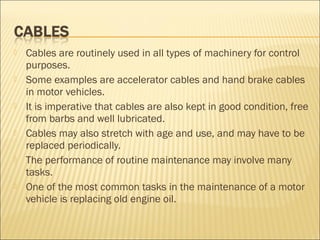
![ The oil filter catches small particles of dirt and metal in the oil,
which could otherwise cause damage inside the engine.
Eventually, the filter starts to clog up and the oil can’t flow
through it as easily.
If the filter clogs up completely, a bypass valve will open so that
some oil can still reach the engine, but dirt and metal particles
will be circulating as well.
A new filter should always be fitted whenever the engine oil is
changed.
Always make sure that the correct filter for the particular
engine is used.
Engine oil is typically replaced after 10 000 km of driving.
repoilfilter_cable[1].wmv
The cartridge type oil filter](https://image.slidesharecdn.com/9maintenance-091001063919-phpapp02/85/Mechanical-Technology-Grade-10-Chapter-9-Maintenance-34-320.jpg)
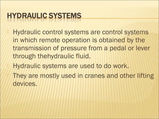

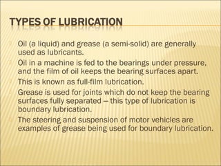
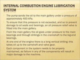
The document details the importance of machinery maintenance, highlighting the need for routine tasks like inspection, lubrication, and part replacement to prevent wear and machine failure. It explains the role of lubricants, particularly oil and grease, in reducing friction and extending the lifespan of components, as well as discussing different types of lubrication systems. Additionally, it covers failure causes and the significance of regular maintenance in hydraulic and pneumatic systems to ensure operational safety.