Downloaded 196 times
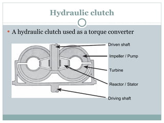

This document discusses various mechanical and hydraulic components, including gears, pulleys, belts, linkages, clutches, levers, and valves, outlining their functions and applications. It highlights the principles of power transmission and control using both mechanical and electronic systems in machinery. Additionally, it covers the importance of maintaining efficiency in hydraulic and pneumatic systems through appropriate design and alignment.