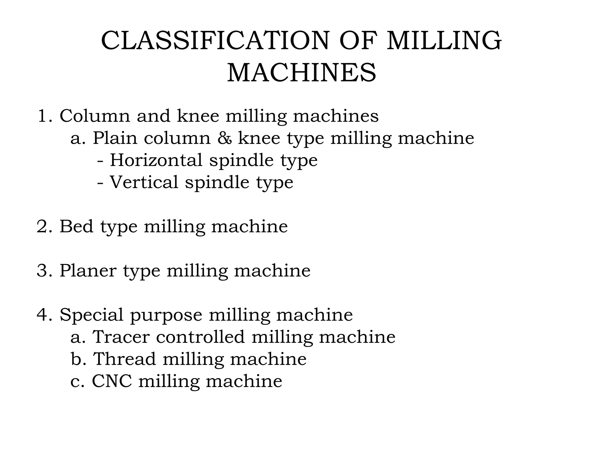
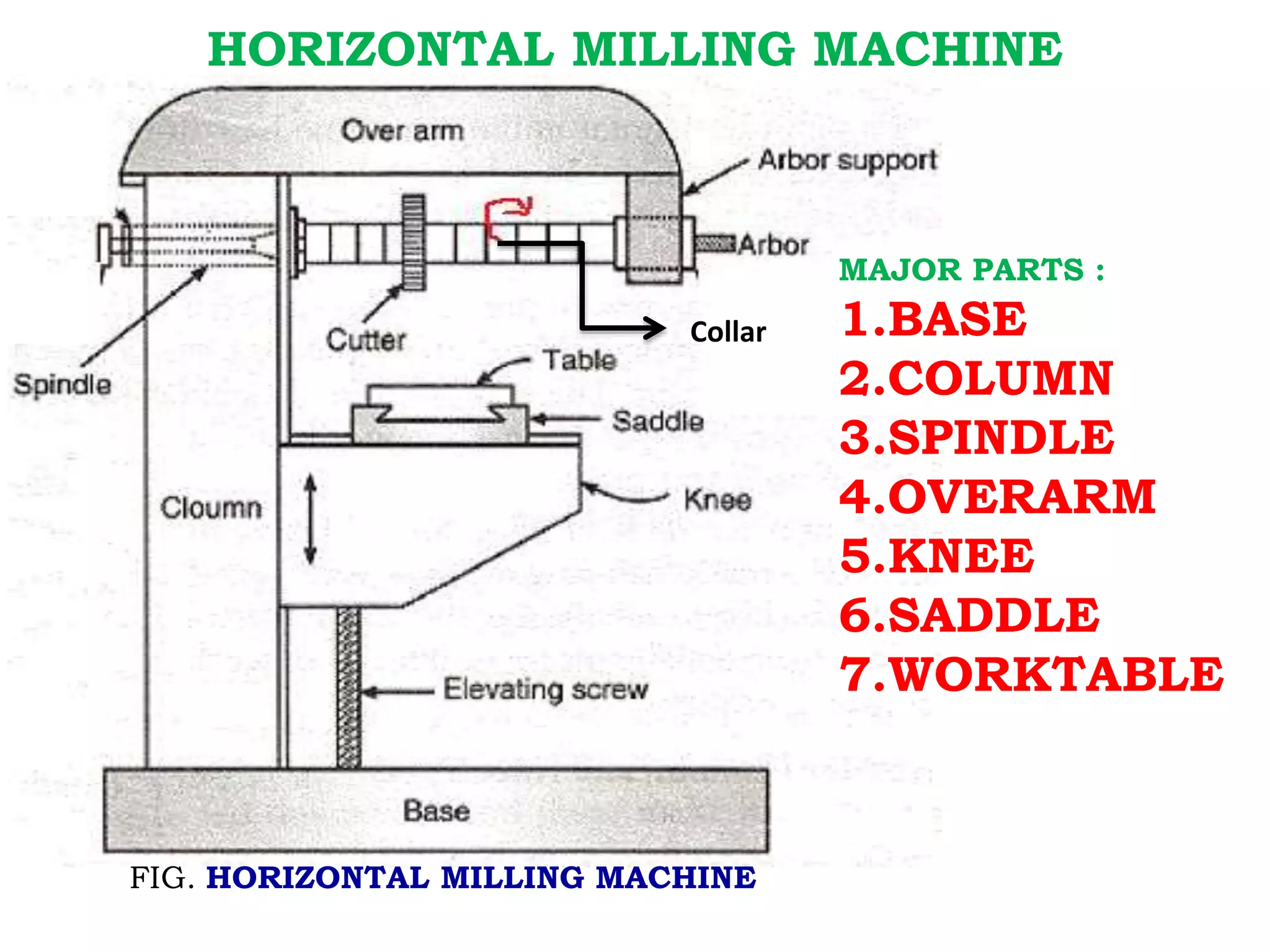
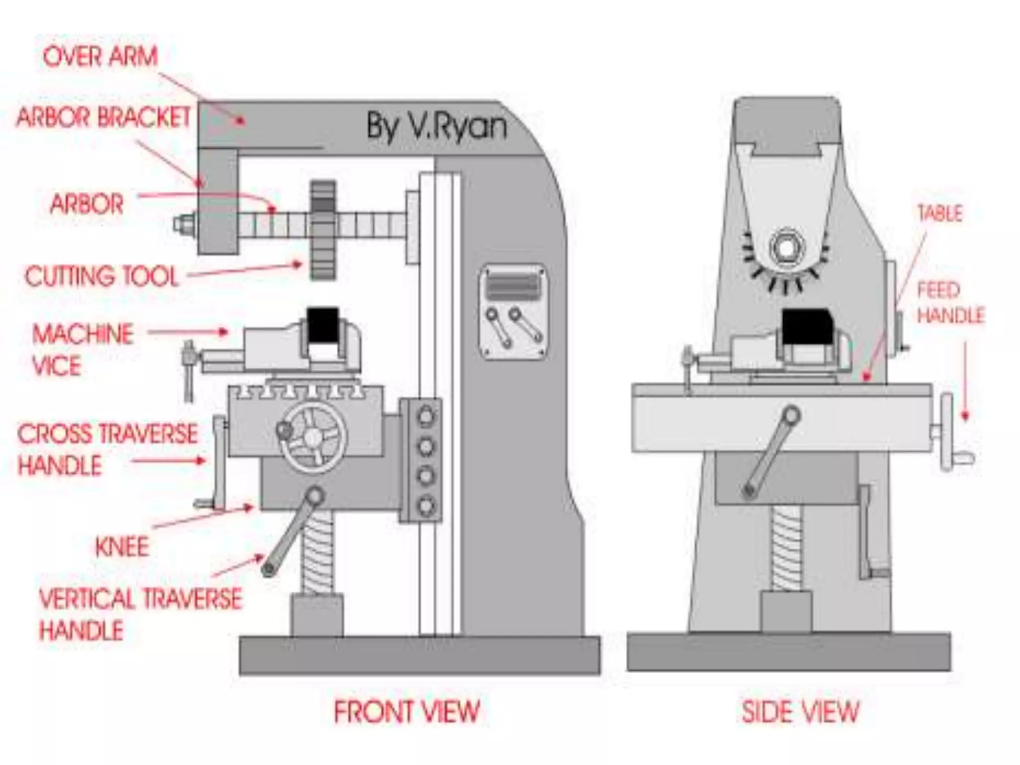
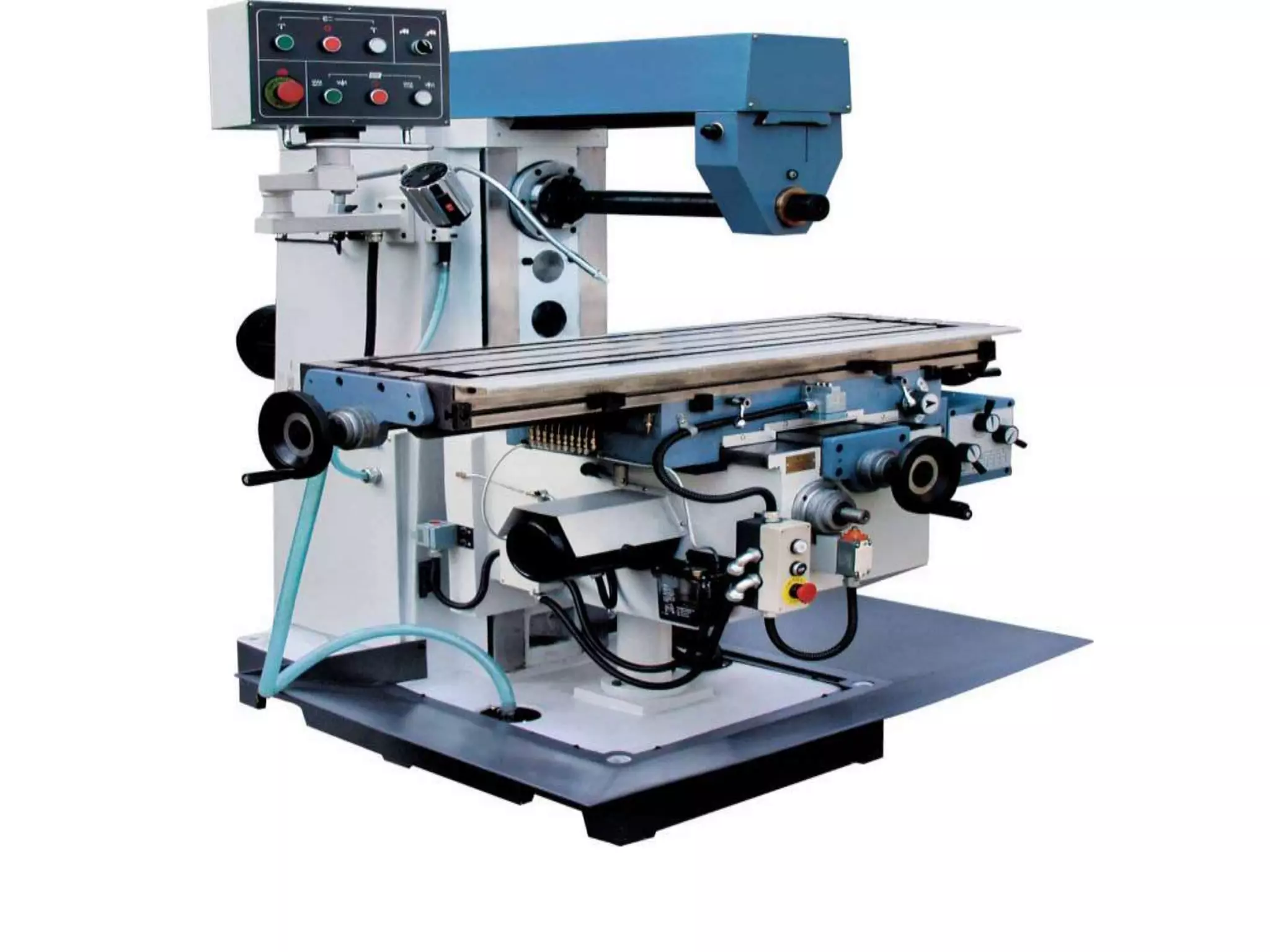
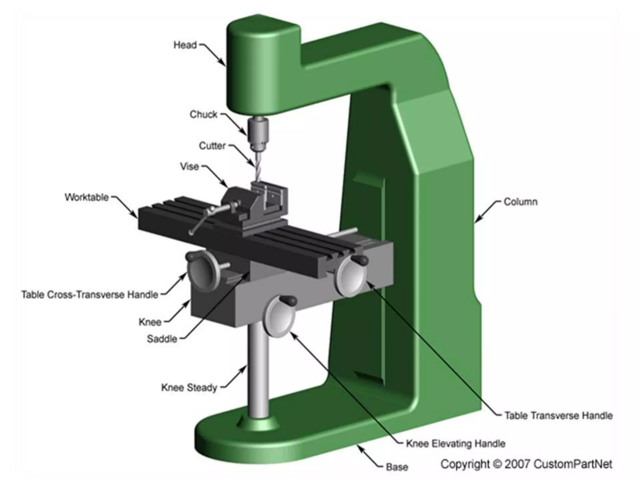
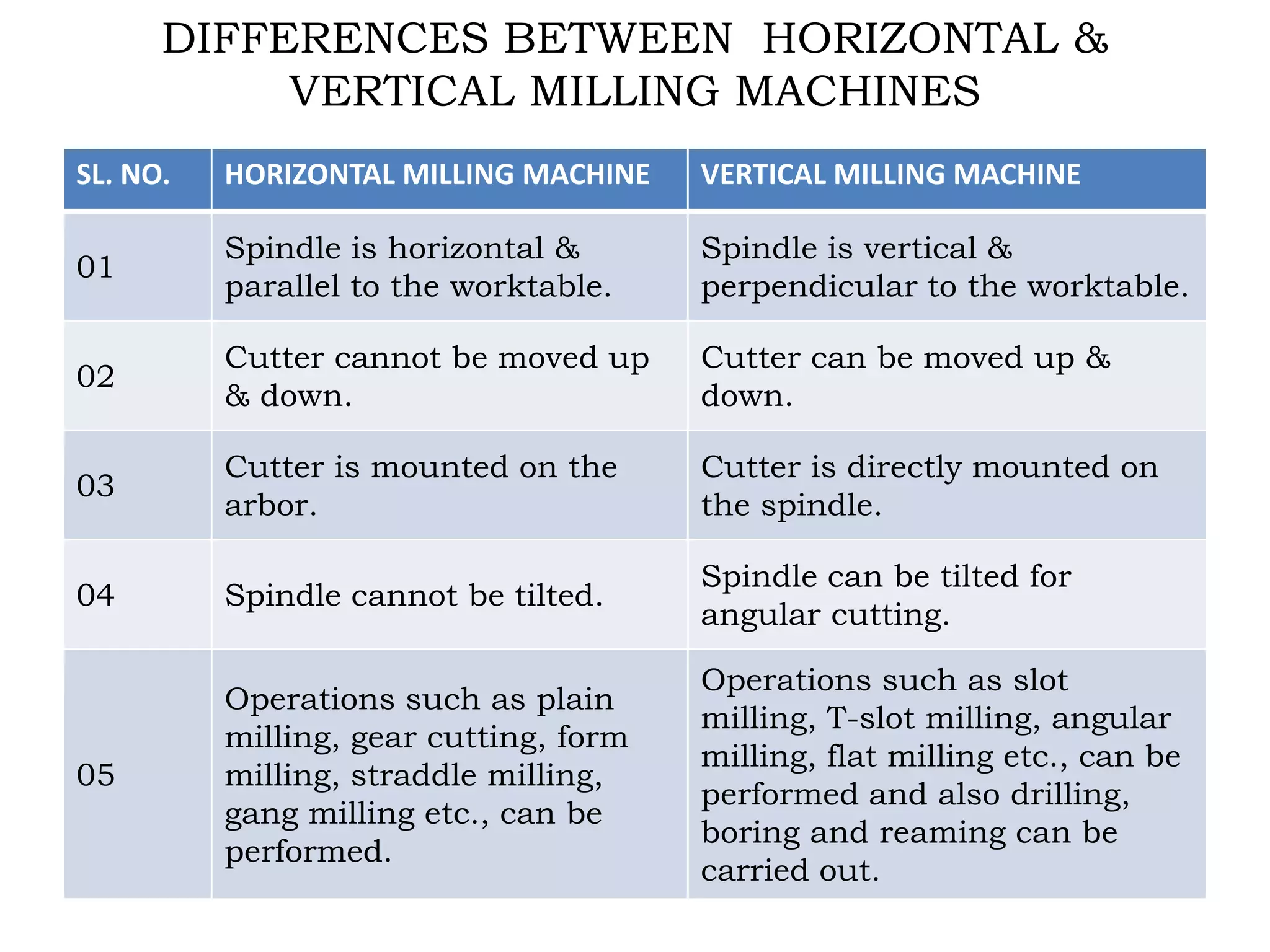
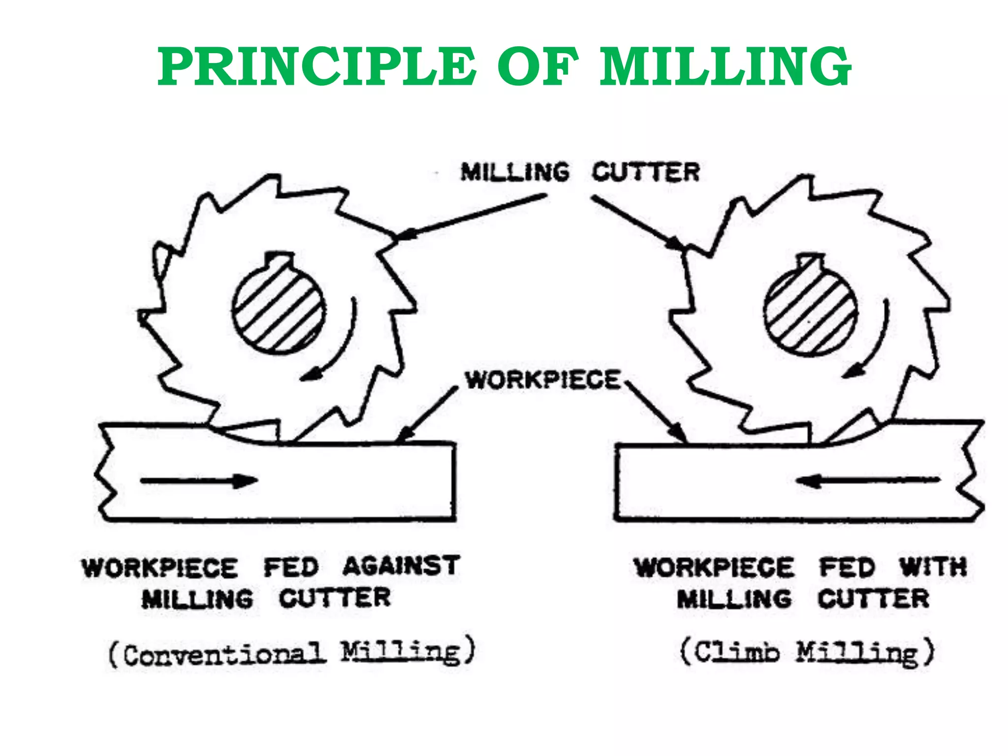
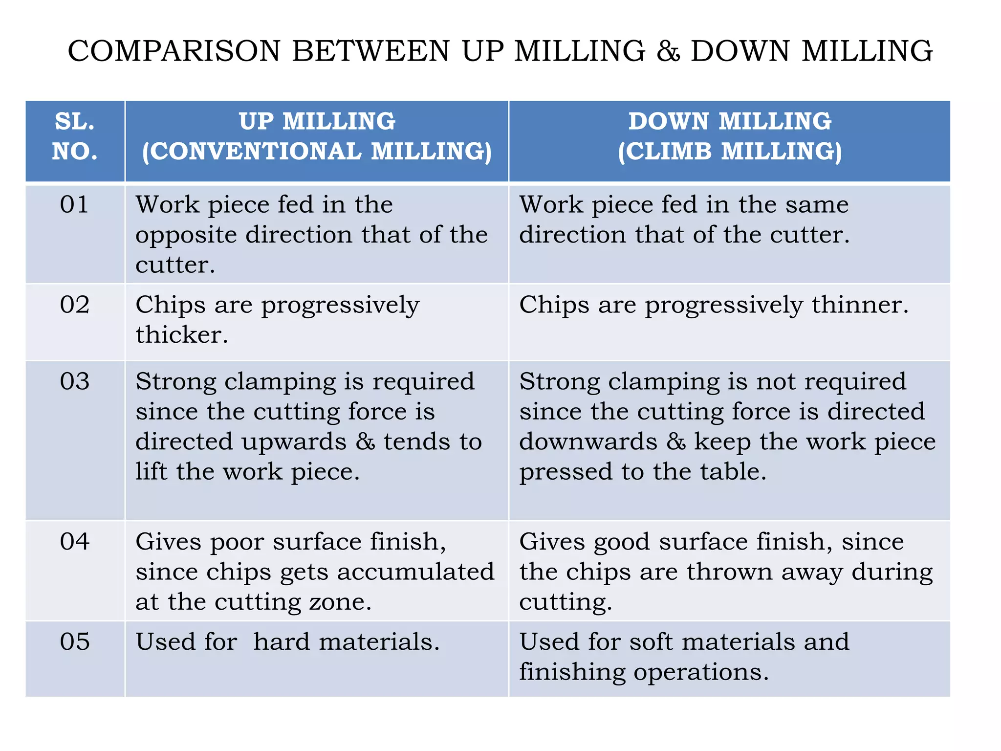
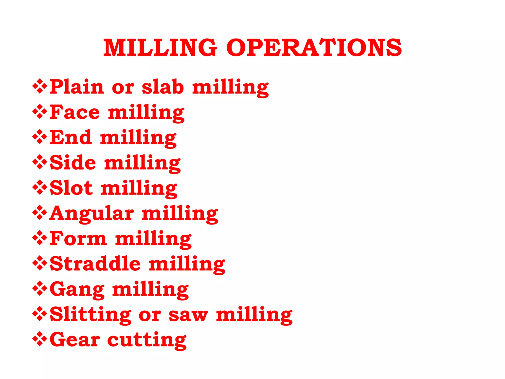
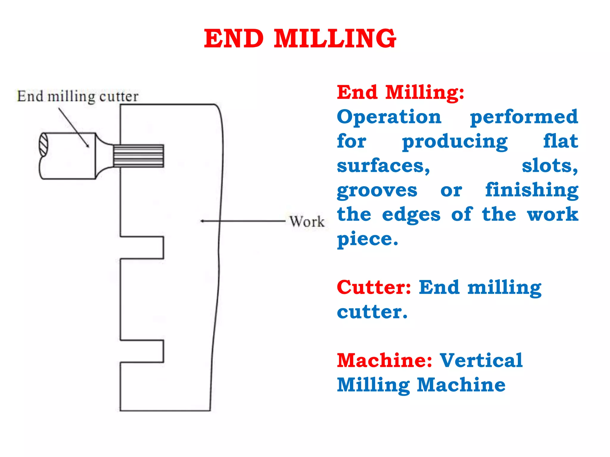
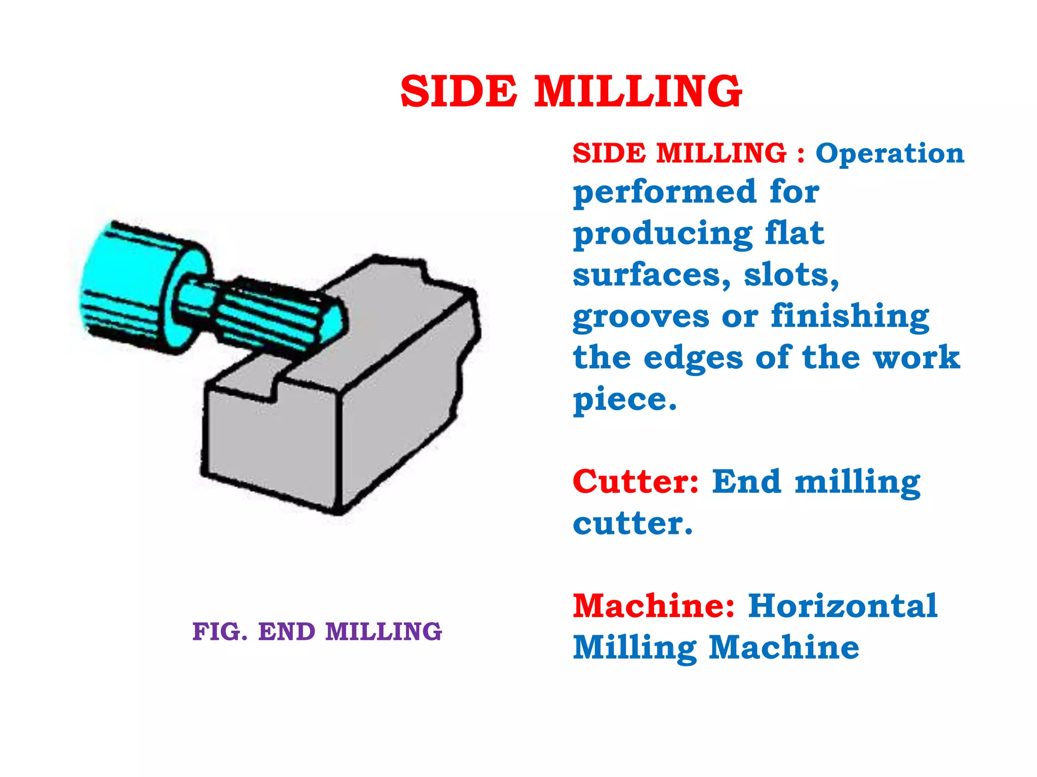
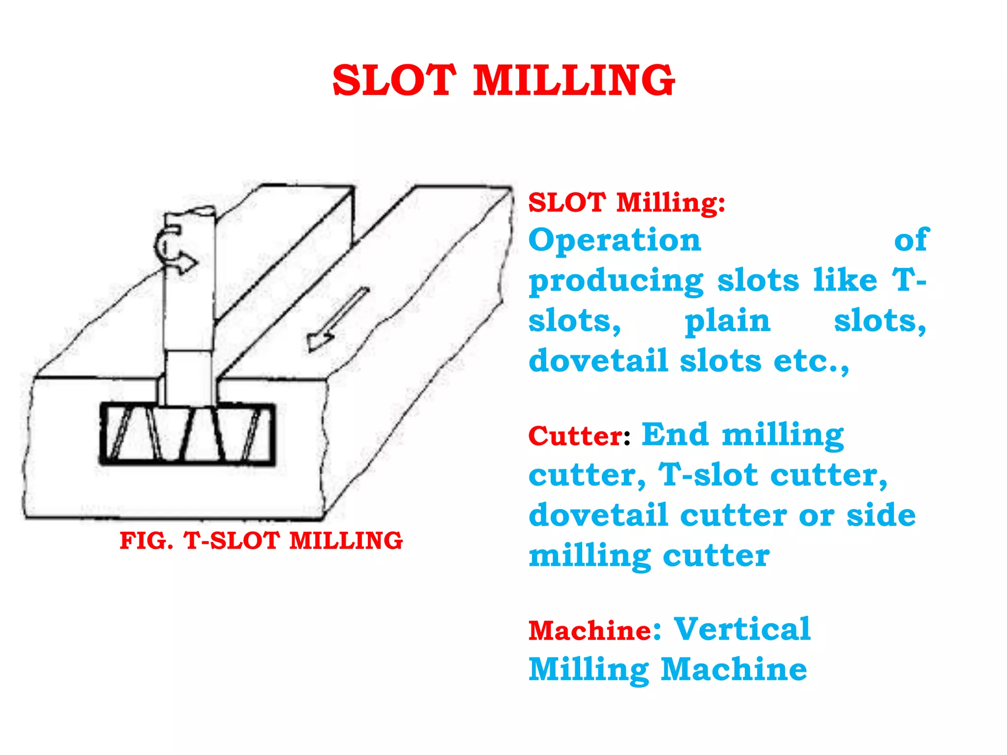
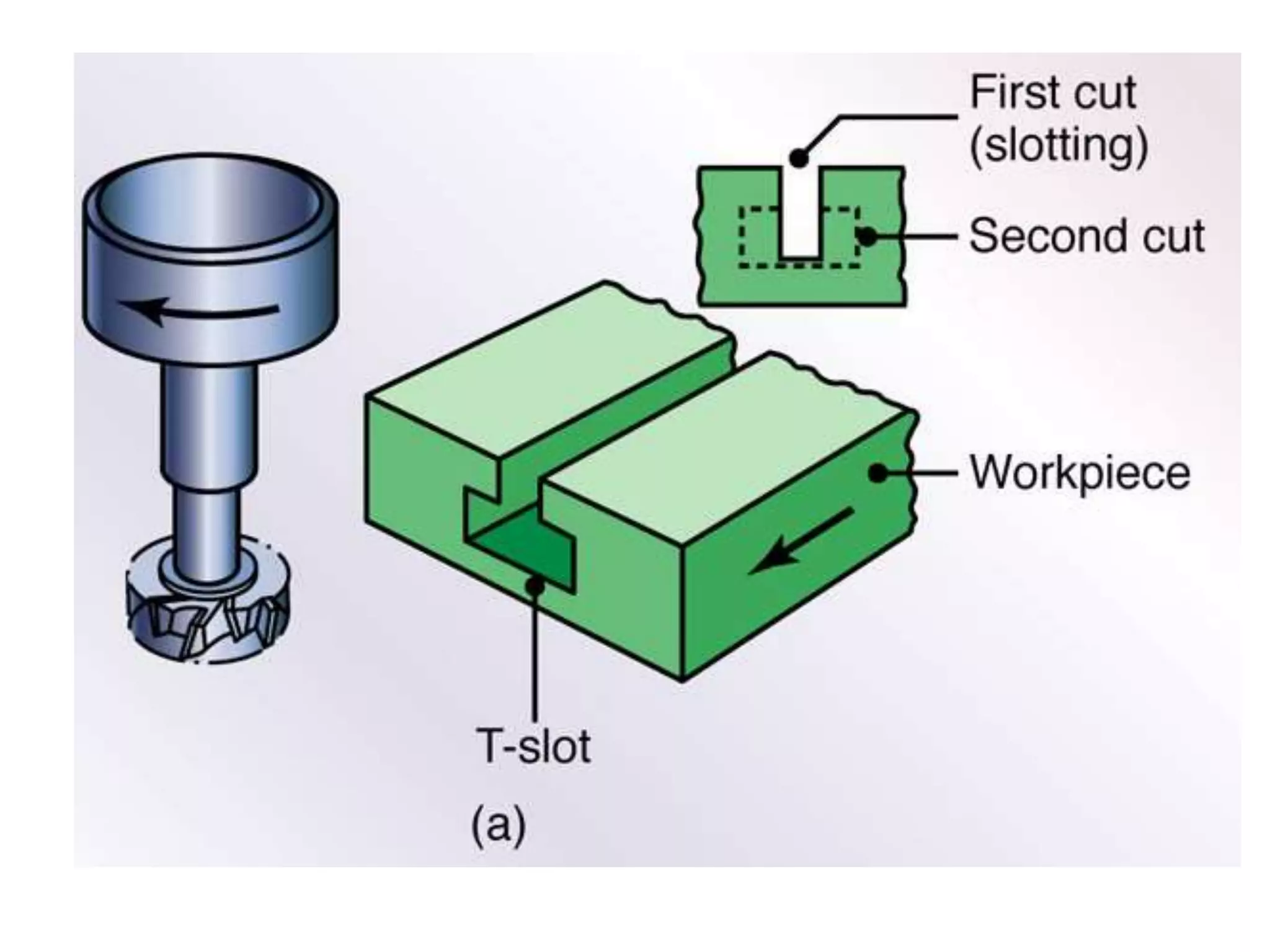
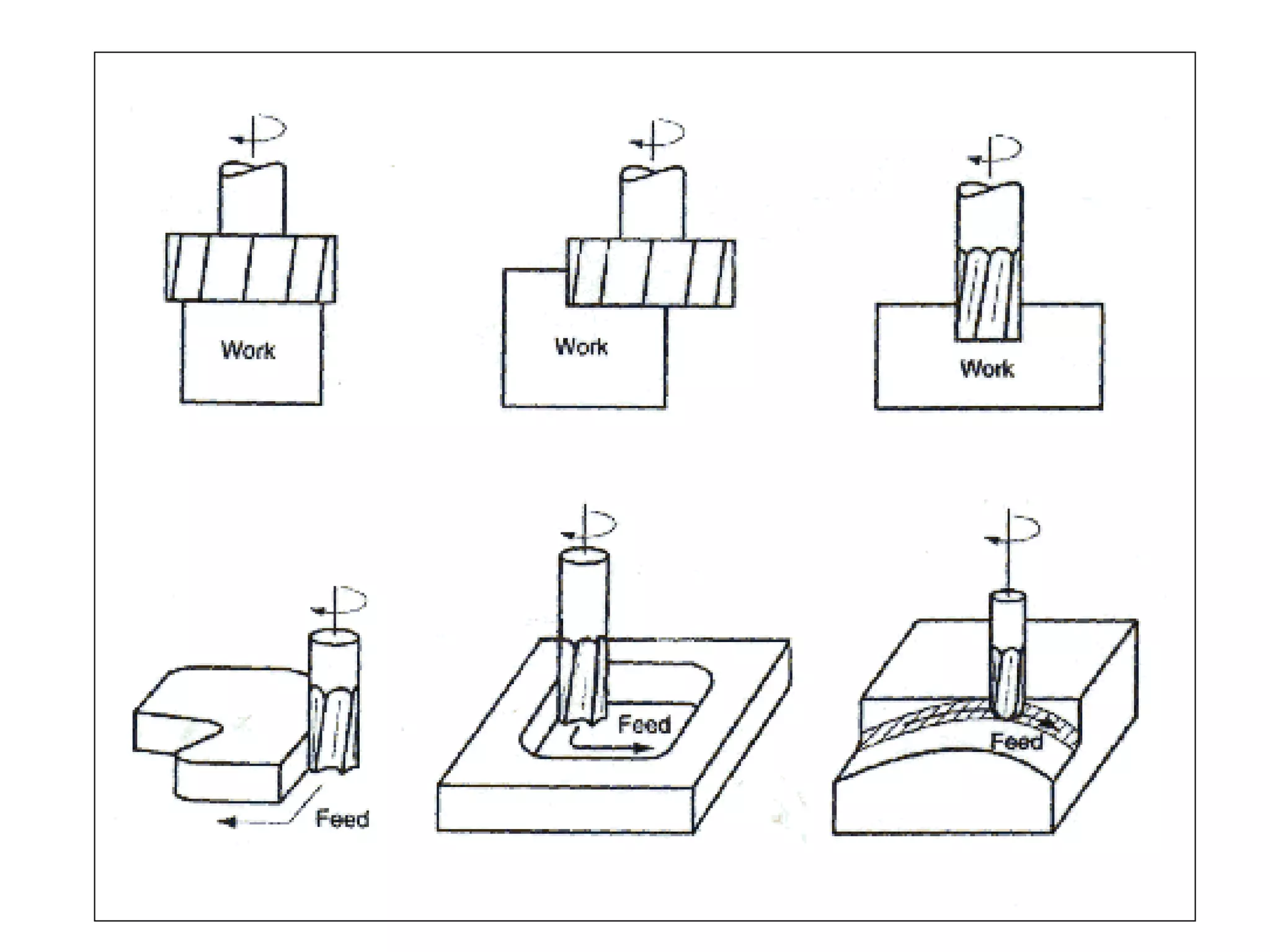
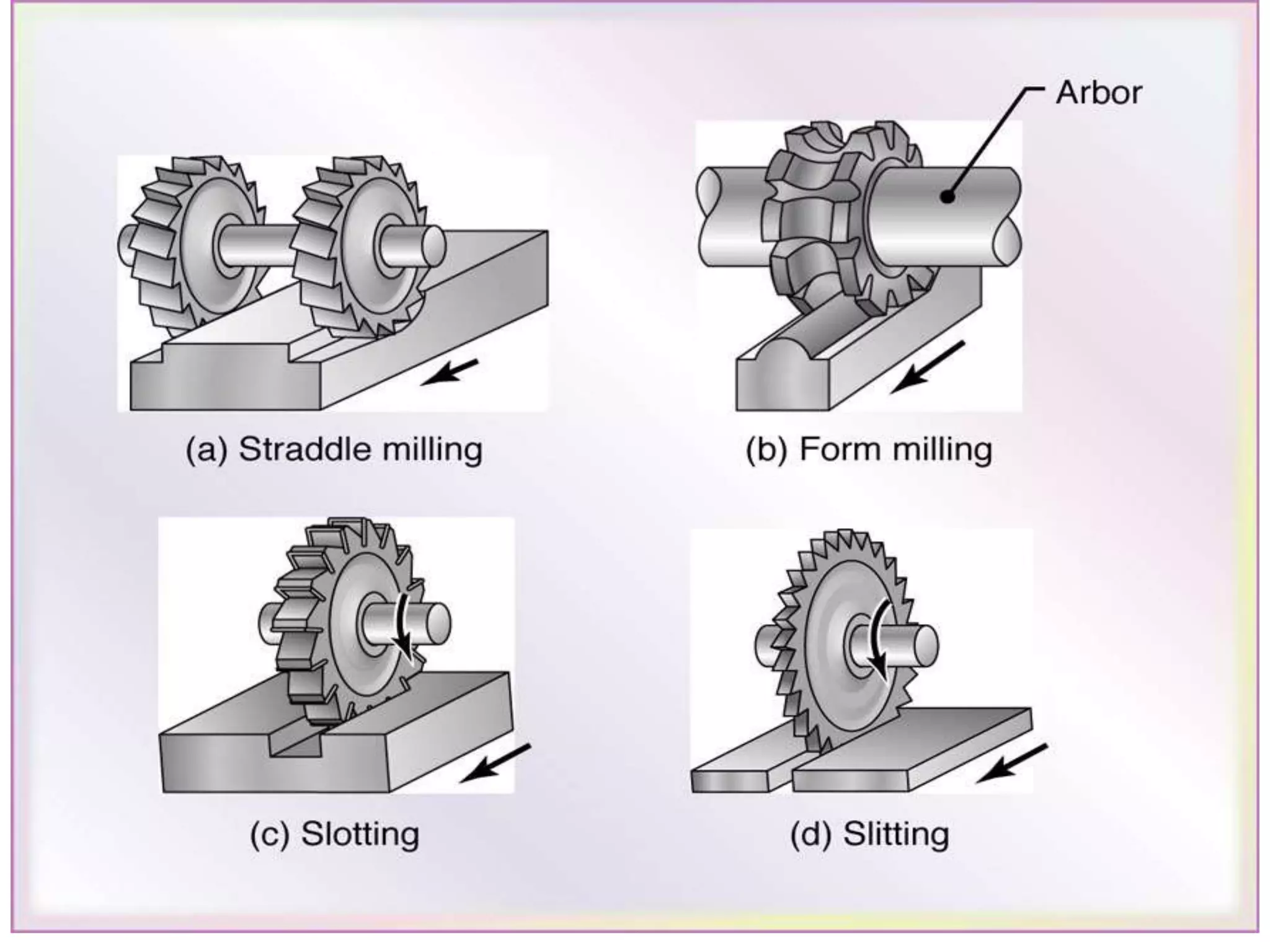
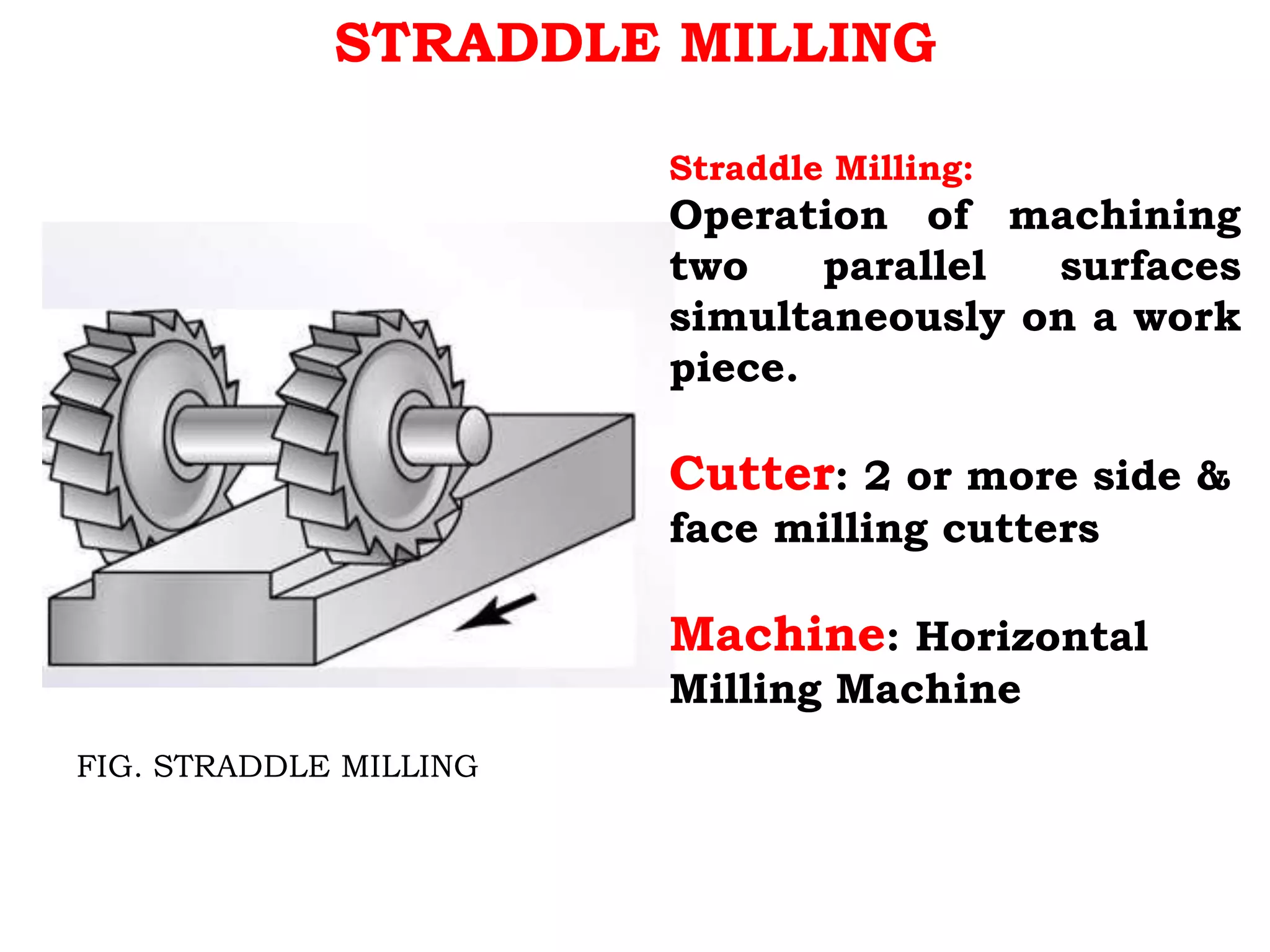
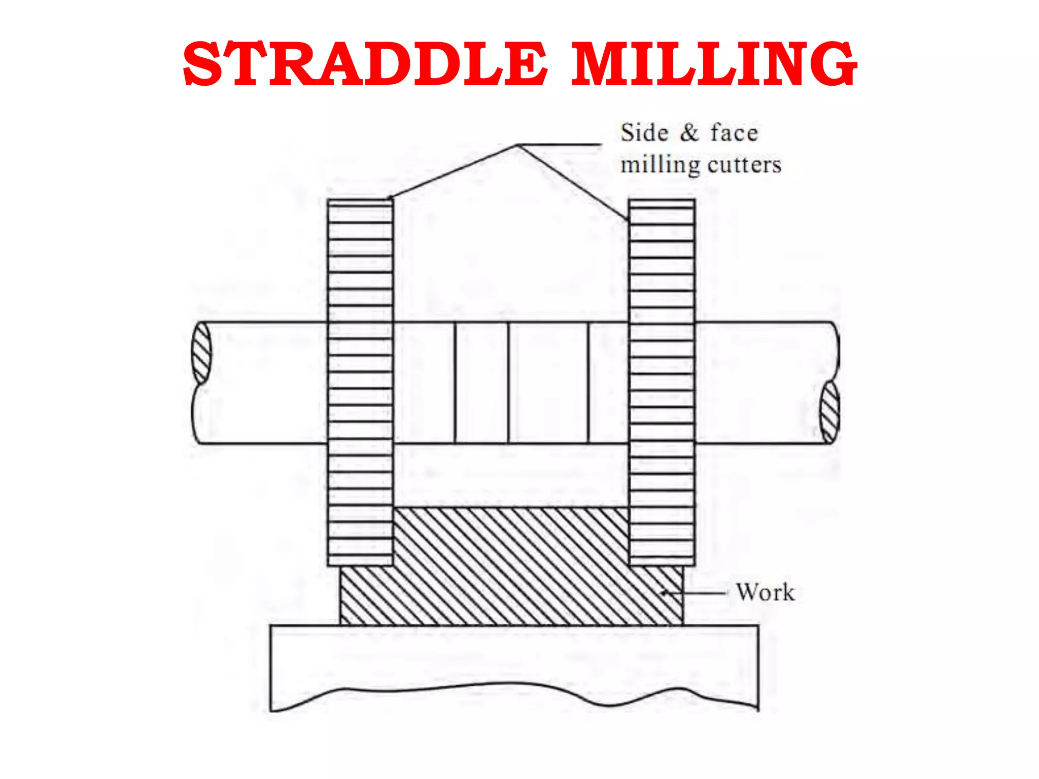
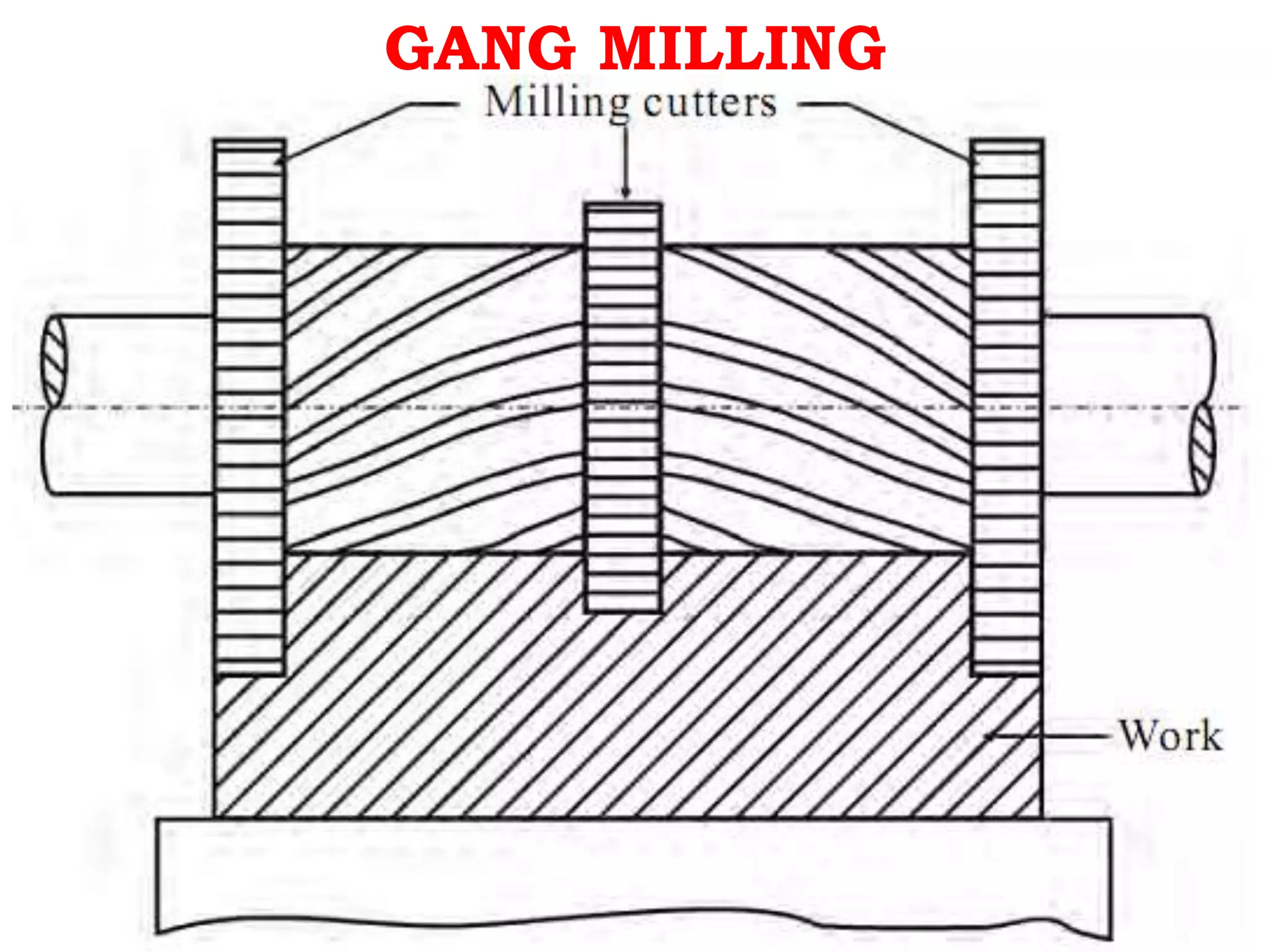
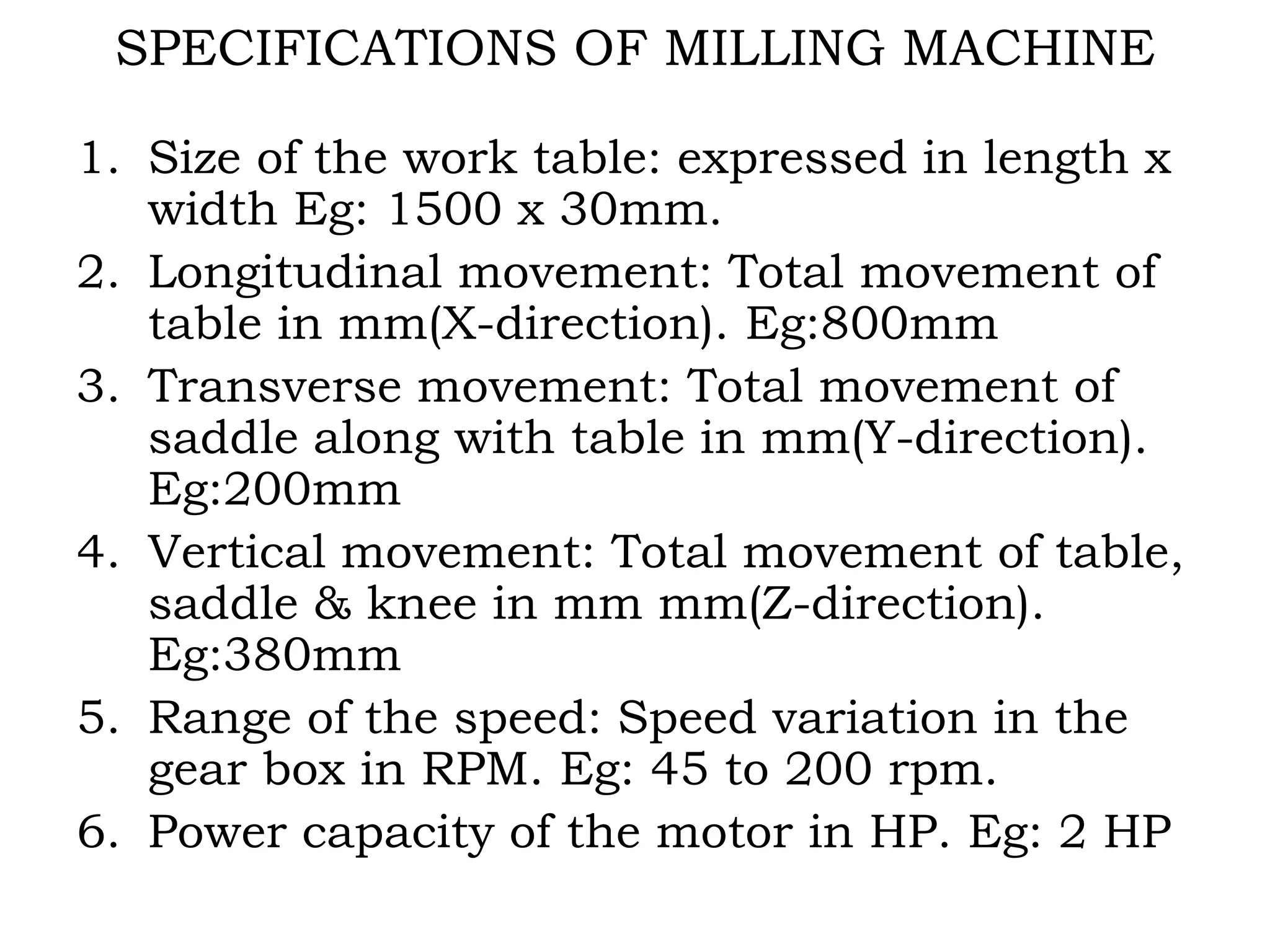
4. MILLING
Milling: is a metal cutting operation in
which the excess material from the work
piece is removed by rotating multipoint
cutting tool called milling cutter.
Milling machine: is a power operated
machine tool in which work piece mounted
on a moving table is machined to various
shapes when moved under a slow revolving
serrated cutter.
5. CLASSIFICATION OF MILLING
MACHINES
1. Column and knee milling machines
a. Plain column & knee type milling machine
- Horizontal spindle type
- Vertical spindle type
2. Bed type milling machine
3. Planer type milling machine
4. Special purpose milling machine
a. Tracer controlled milling machine
b. Thread milling machine
c. CNC milling machine
6. HORIZONTAL MILLING MACHINE
FIG. HORIZONTAL MILLING MACHINE
MAJOR PARTS :
1.BASE
2.COLUMN
3.SPINDLE
4.OVERARM
5.KNEE
6.SADDLE
7.WORKTABLE
Collar
11. DIFFERENCES BETWEEN HORIZONTAL &
VERTICAL MILLING MACHINES
SL. NO. HORIZONTAL MILLING MACHINE VERTICAL MILLING MACHINE
01
Spindle is horizontal &
parallel to the worktable.
Spindle is vertical &
perpendicular to the worktable.
02
Cutter cannot be moved up
& down.
Cutter can be moved up &
down.
03
Cutter is mounted on the
arbor.
Cutter is directly mounted on
the spindle.
04 Spindle cannot be tilted.
Spindle can be tilted for
angular cutting.
05
Operations such as plain
milling, gear cutting, form
milling, straddle milling,
gang milling etc., can be
performed.
Operations such as slot
milling, T-slot milling, angular
milling, flat milling etc., can be
performed and also drilling,
boring and reaming can be
carried out.
13. COMPARISON BETWEEN UP MILLING & DOWN MILLING
SL.
NO.
UP MILLING
(CONVENTIONAL MILLING)
DOWN MILLING
(CLIMB MILLING)
01 Work piece fed in the
opposite direction that of the
cutter.
Work piece fed in the same
direction that of the cutter.
02 Chips are progressively
thicker.
Chips are progressively thinner.
03 Strong clamping is required
since the cutting force is
directed upwards & tends to
lift the work piece.
Strong clamping is not required
since the cutting force is directed
downwards & keep the work piece
pressed to the table.
04 Gives poor surface finish,
since chips gets accumulated
at the cutting zone.
Gives good surface finish, since
the chips are thrown away during
cutting.
05 Used for hard materials. Used for soft materials and
finishing operations.
15. PLAIN/SURFACE/ SLAB MILLING
FIG. PLAIN MILLING
Plain Milling:
Process to get the flat
surface on the work
piece in which the
cutter axis and work
piece axis are parallel.
Cutter: Plain/ Slab
milling cutter.
Machine: Horizontal
Milling m/c.
17. FACE MILLING
FIG. FACE MILLING
Face Milling:
Operation carried out
for producing a flat
surface, which is
perpendicular to the
axis of rotating
cutter.
Cutter: Face milling cutter.
Machine: Vertical Milling
Machine
18. END MILLING
FIG. END MILLING
End Milling:
Operation performed
for producing flat
surfaces, slots,
grooves or finishing
the edges of the work
piece.
Cutter: End milling
cutter.
Machine: Vertical
Milling Machine
19. SIDE MILLING
FIG. END MILLING
SIDE MILLING : Operation
performed for
producing flat
surfaces, slots,
grooves or finishing
the edges of the work
piece.
Cutter: End milling
cutter.
Machine: Horizontal
Milling Machine
20. SLOT MILLING
FIG. T-SLOT MILLING
SLOT Milling:
Operation of
producing slots like T-
slots, plain slots,
dovetail slots etc.,
Cutter: End milling
cutter, T-slot cutter,
dovetail cutter or side
milling cutter
Machine: Vertical
Milling Machine
21.
22.
23. ANGULAR MILLING
FIG. ANGULAR MILLING
Angular Milling:
Operation of
producing all types of
angular cuts like V-
notches and grooves,
serrations and angular
surfaces.
Cutter: Double angle
cutter.
Machine: Horizontal
Milling Machine
24. FORM MILLING
End Milling:
Operation of producing
all types of angular cuts
like V-notches and
grooves, serrations and
angular surfaces.
Cutter: Double angle
cutter.
Machine: Horizontal
Milling Machine
27. STRADDLE MILLING
FIG. STRADDLE MILLING
Straddle Milling:
Operation of machining
two parallel surfaces
simultaneously on a work
piece.
Cutter: 2 or more side &
face milling cutters
Machine: Horizontal
Milling Machine
29. GANG MILLING
FIG. GANG MILLING
Gang Milling:
Process to get
different profiles on
the work piece
simultaneously with
two or more cutters
at one stretch.
Cutter: Different
cutters as required.
Machine: Horizontal
Milling Machine
34. 1.Plain milling cutter
The most common
milling cutter is known
as a plain milling
cutter. It is merely a
metal cylinder having
teeth cut on its
periphery for
producing a flat
horizontal surface
35. 1(a).SLAB MILLING CUTTER
• Cutter width extends beyond the work piece
on both sides
• Process where axis of cutting tool is
parallel to the work piece surface to be
machined
• Used to create flat surfaces or slots
• Cutter may have either straight or
helical teeth
38. 2.SIDE MILLING CUTTER
Side milling cutters have teeth on its
periphery and also on one or both of
its sides. They are intended for
removing metal from the sides of the
work piece. There are different types
of side milling cutters namely face
and side milling cutter, half side
milling cutter.
40. 3.END MILLING CUTTERS
These cutters have cutting
teeth on the end as well as on
the periphery of the cutter. It
is made of two parts – body
and shank. The shanks of the
cutter may be straight or
taper.
42. 4.Metal slitting saw
• It is intended for cutting narrow,
deep slots and for parting off
operation. The teeth are cut on the
circumference of the cutter. The
width of the cutter is limited. The
outside diameter of the cutter will
be up to 200mm and width of the
cutter ranges from 0.75mm to
7mm.
44. 5.Angle milling cutter
The teeth of the angle milling
cutter are not parallel to the axis but
are at an angle to it. By using angle
milling cutter, inclined surfaces,
bevels and helical grooves are
machined. There are two types of
angle milling cutter
1. Single angle milling cutter and
2.double angle milling cutter.
46. 6. ‘T’ – Slot milling cutter.
It is a special form of end
mills intended for machining
‘T’- slots. It looks like a side
milling cutter with a shank. The
cutters have cutting teeth on
the periphery as well as on
both sides of the cutter.
48. 7. Fly cutter
Fly cutter is the simplest form of cutter. It
consists of a single point cutting tool
attached to the end of the arbor. The
cutting edge may be formed to reproduce
a contoured surface. They are used when
standard cutters are not available. The
work is done very slowly because of a
single cutting edge.
50. 8.Formed cutter
Formed cutters have irregular
profiles on their cutting edges to
produce required outlines on the
work. Concave and convex milling
cutters are used to produce
convex and concave surfaces
respectively.
51. SPECIFICATIONS OF MILLING MACHINE
1. Size of the work table: expressed in length x
width Eg: 1500 x 30mm.
2. Longitudinal movement: Total movement of
table in mm(X-direction). Eg:800mm
3. Transverse movement: Total movement of
saddle along with table in mm(Y-direction).
Eg:200mm
4. Vertical movement: Total movement of table,
saddle & knee in mm mm(Z-direction).
Eg:380mm
5. Range of the speed: Speed variation in the
gear box in RPM. Eg: 45 to 200 rpm.
6. Power capacity of the motor in HP. Eg: 2 HP