Downloaded 1,069 times
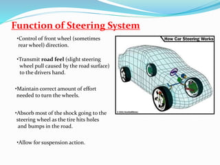
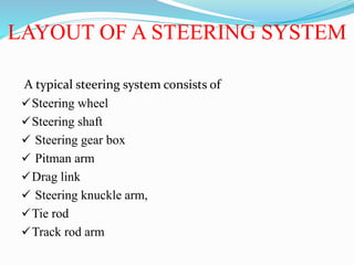
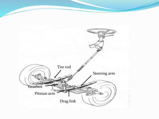
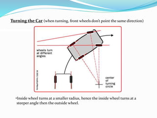
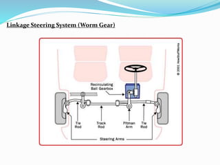
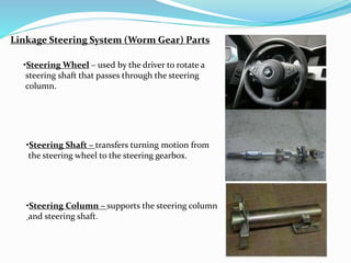
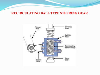
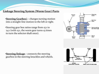
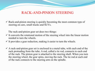
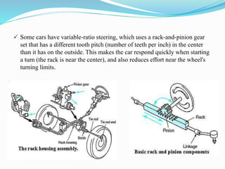
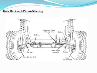
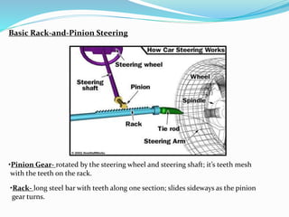
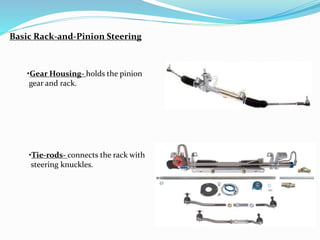
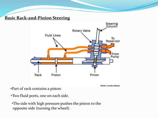
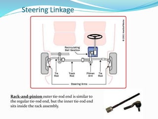
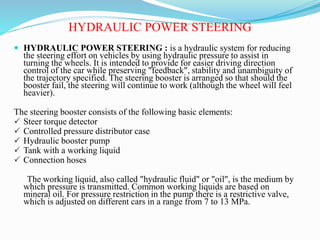
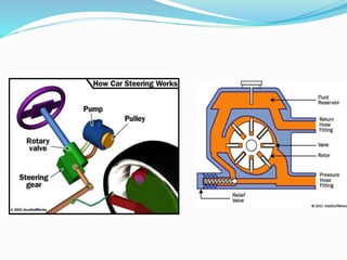
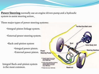


The document summarizes the components and functions of an automobile steering system. It describes the key parts that transfer motion from the steering wheel to the front wheels, including the steering column, gearbox, linkage, and rack-and-pinion assembly. It also explains the purposes of the steering system to control direction, maintain effort levels, absorb shocks, and allow for suspension movement, while highlighting common steering system types like recirculating ball, rack-and-pinion, and hydraulic power steering.


