Downloaded 30 times
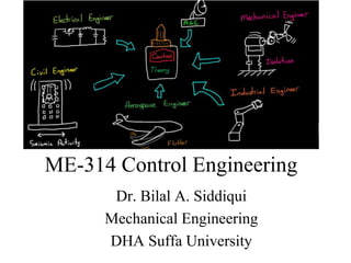
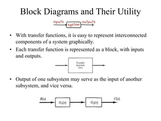
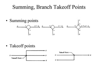
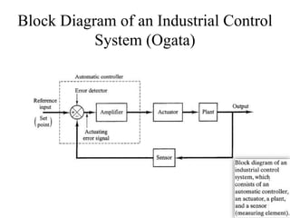

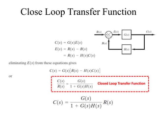
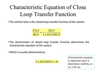


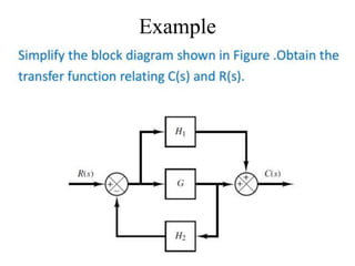
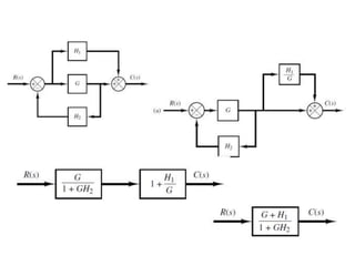
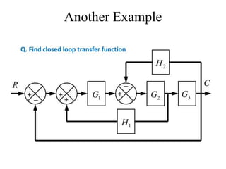


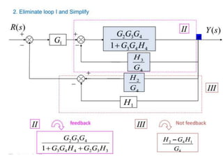
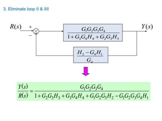
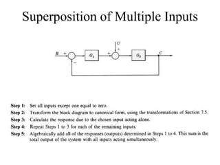
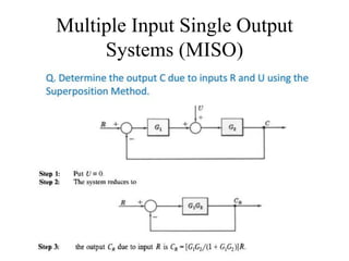

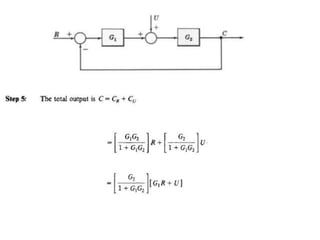
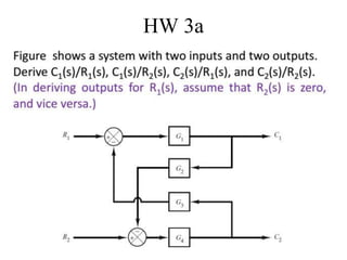

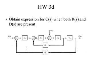
The document discusses block diagrams and their utility in control engineering, highlighting how transfer functions can represent interconnected system components graphically. It explains critical concepts like summing points, takeoff points, and the importance of the characteristic equation of closed-loop transfer functions for stability. Additionally, it includes examples and homework assignments related to obtaining transfer functions for multiple input single output systems.


![Reduction of multiple subsystem [compatibility mode]](https://cdn.slidesharecdn.com/ss_thumbnails/reductionofmultiplesubsystemcompatibilitymode-110418075355-phpapp01-thumbnail.jpg?width=640&height=640&fit=bounds)


![ME 312 Mechanical Machine Design [Screws, Bolts, Nuts]](https://cdn.slidesharecdn.com/ss_thumbnails/me312-dsulec10-screws-170213050612-thumbnail.jpg?width=640&height=640&fit=bounds)


![Av 738- Adaptive Filtering - Wiener Filters[wk 3]](https://cdn.slidesharecdn.com/ss_thumbnails/av-738-aft-spr18-lecture03-optimumfilters-weinerwk3-180215235757-thumbnail.jpg?width=640&height=640&fit=bounds)
![ME 312 Mechanical Machine Design - Introduction [Week 1]](https://cdn.slidesharecdn.com/ss_thumbnails/me312-dsulec01-170213050149-thumbnail.jpg?width=640&height=640&fit=bounds)


