This document discusses block diagrams and their importance. It provides three key points:
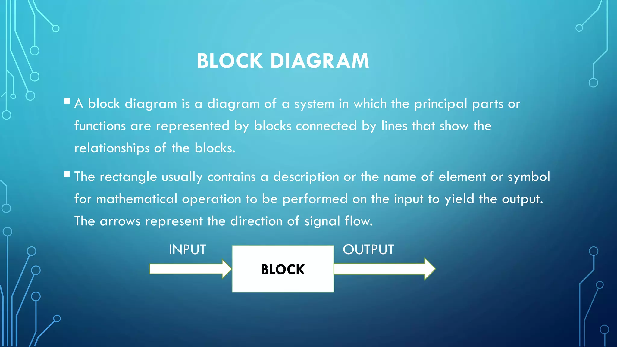
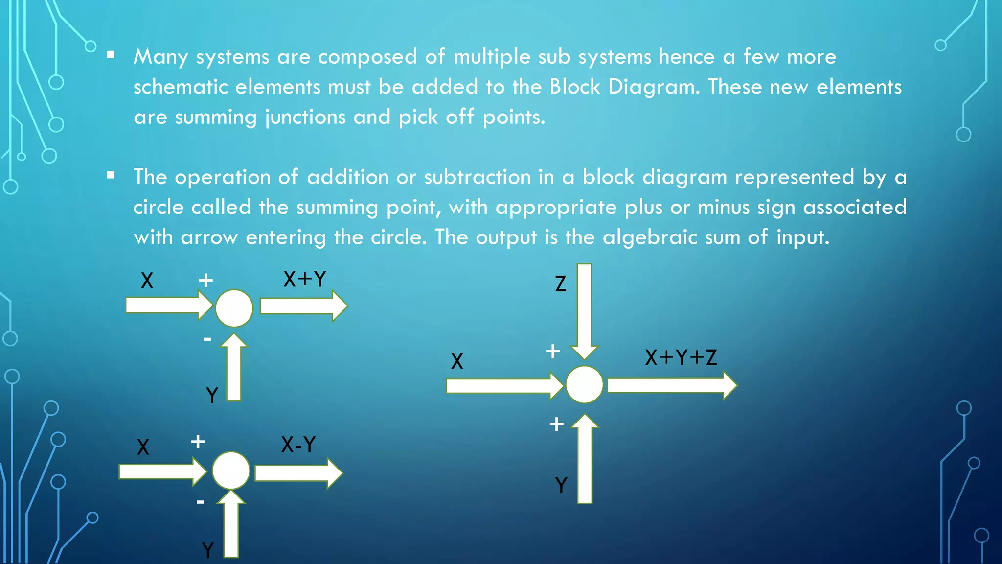
1) A block diagram represents a system using blocks to show the major components and connections showing signal flow. Summing junctions and pick off points are used to show addition/subtraction and splitting of signals.
2) Block diagrams provide a high-level overview of a system, identifying major parts and relationships. This allows quick identification of points of interest or trouble spots.
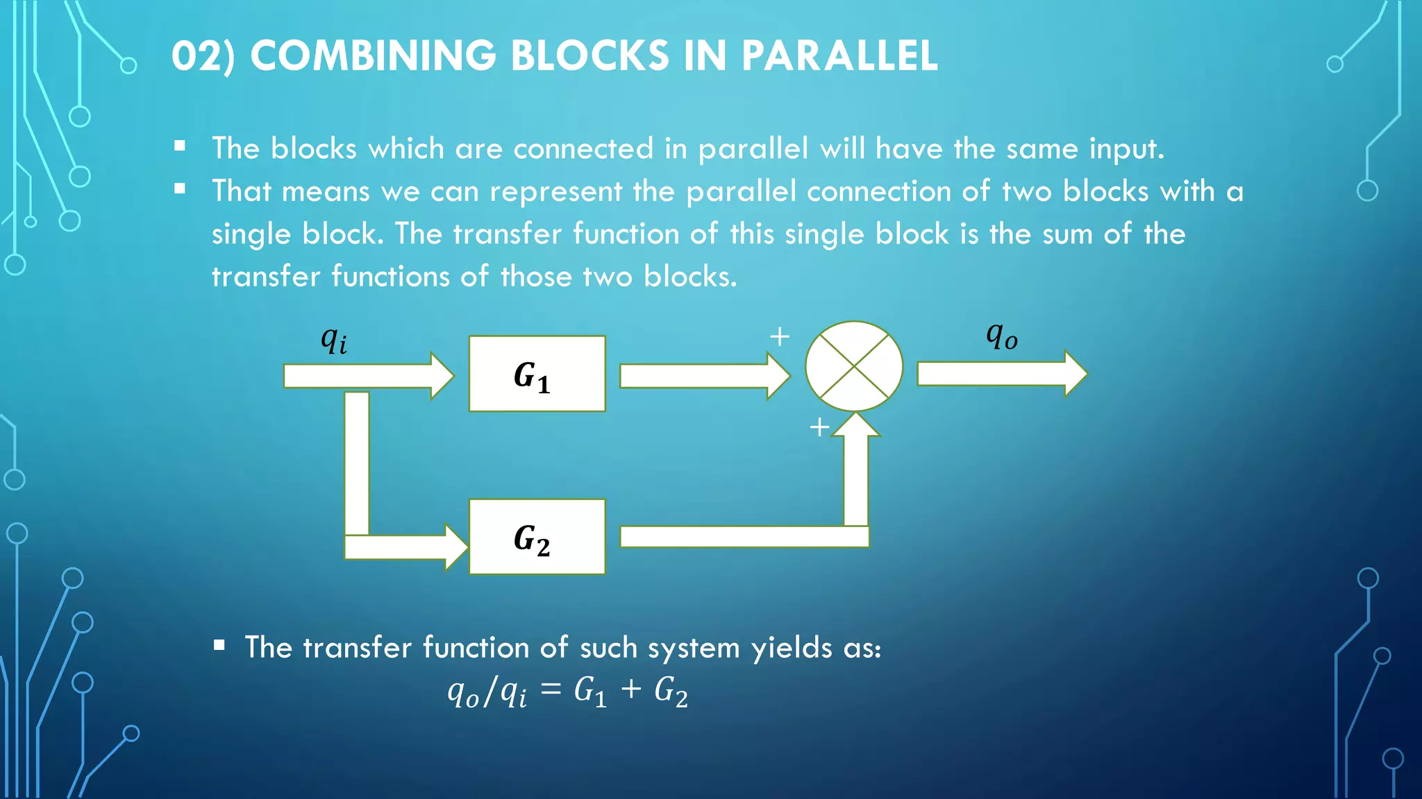
3) Blocks can be combined or reduced in series, parallel, and feedback configurations. The overall transfer function is obtained by multiplying, adding, or applying feedback to the individual block transfer functions.