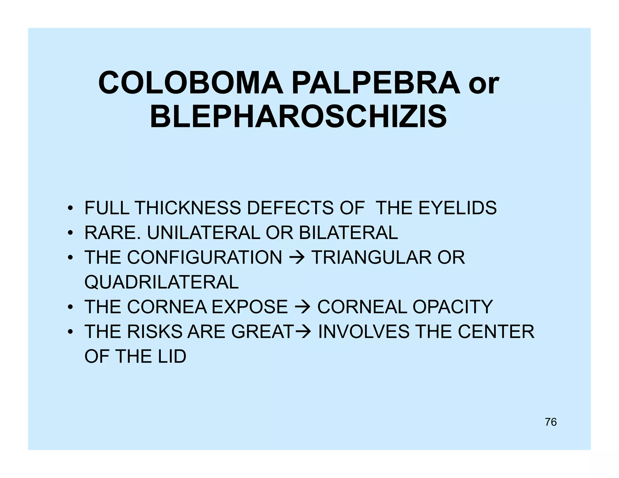
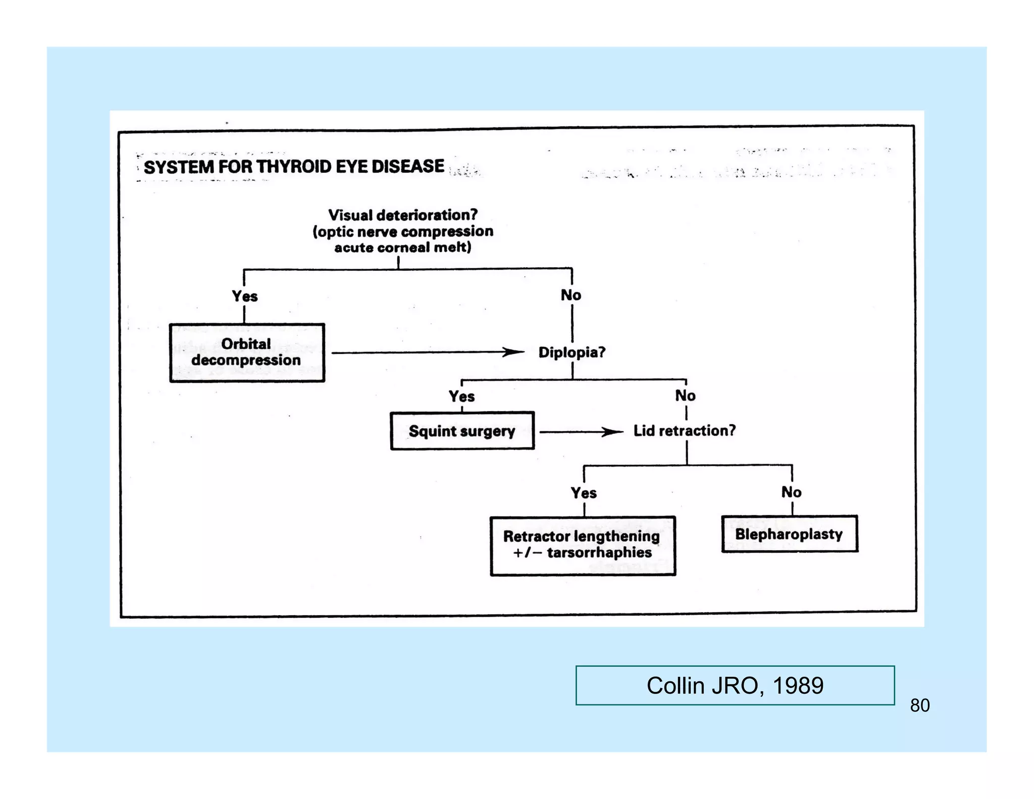
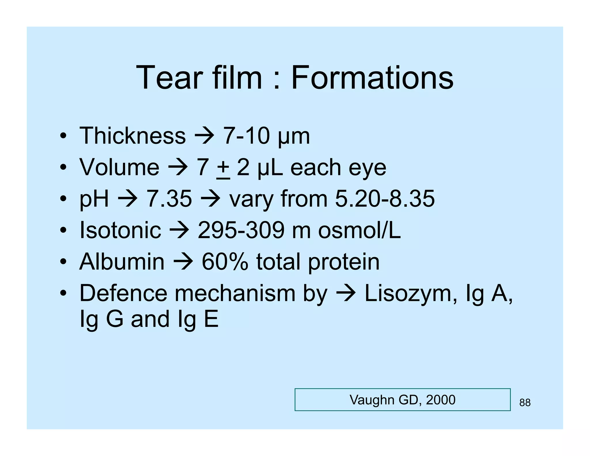
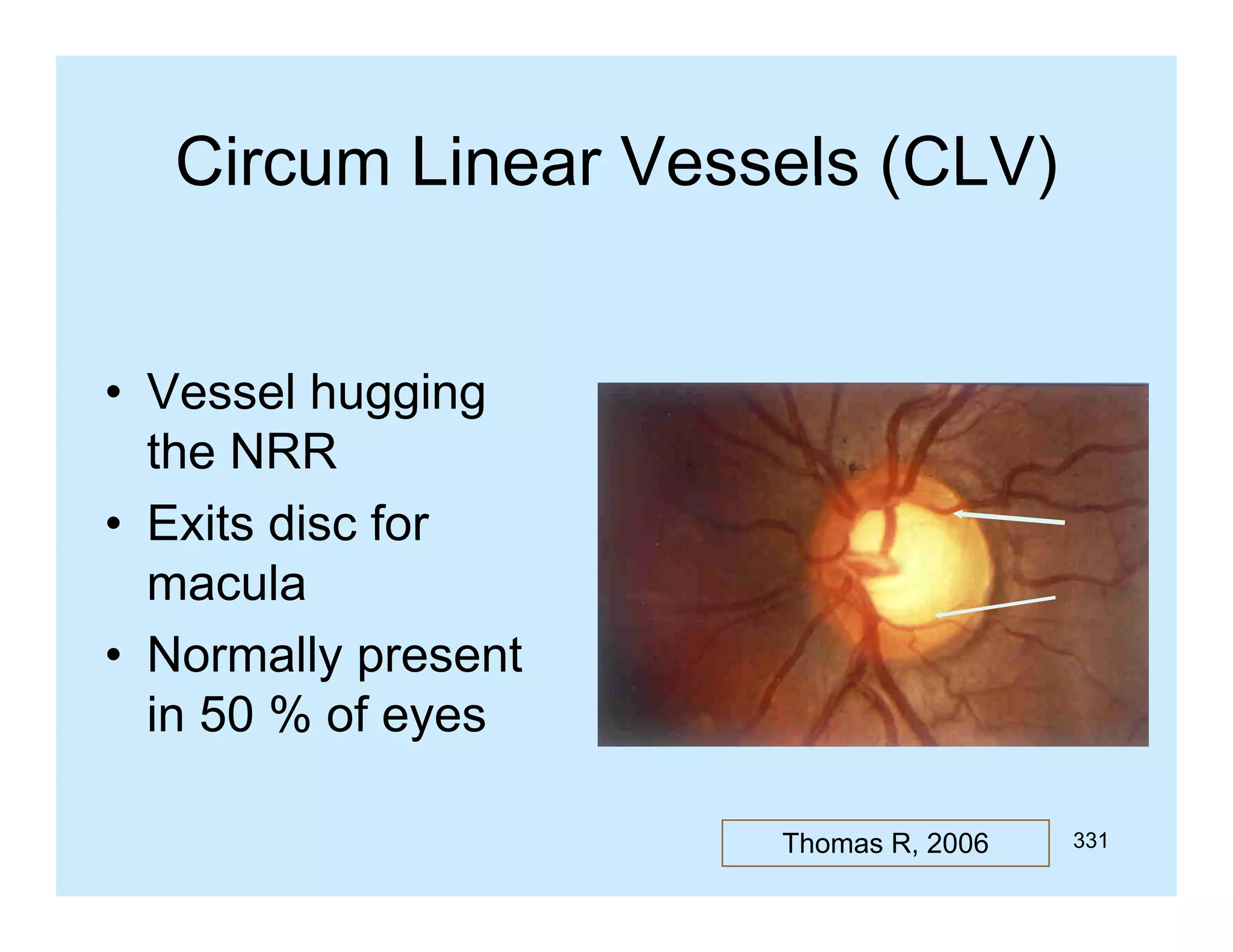
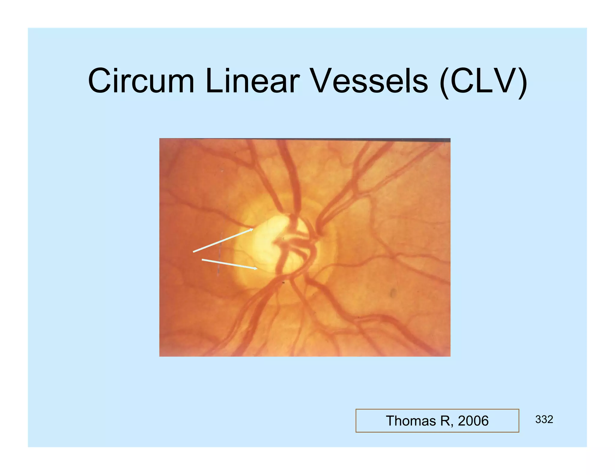
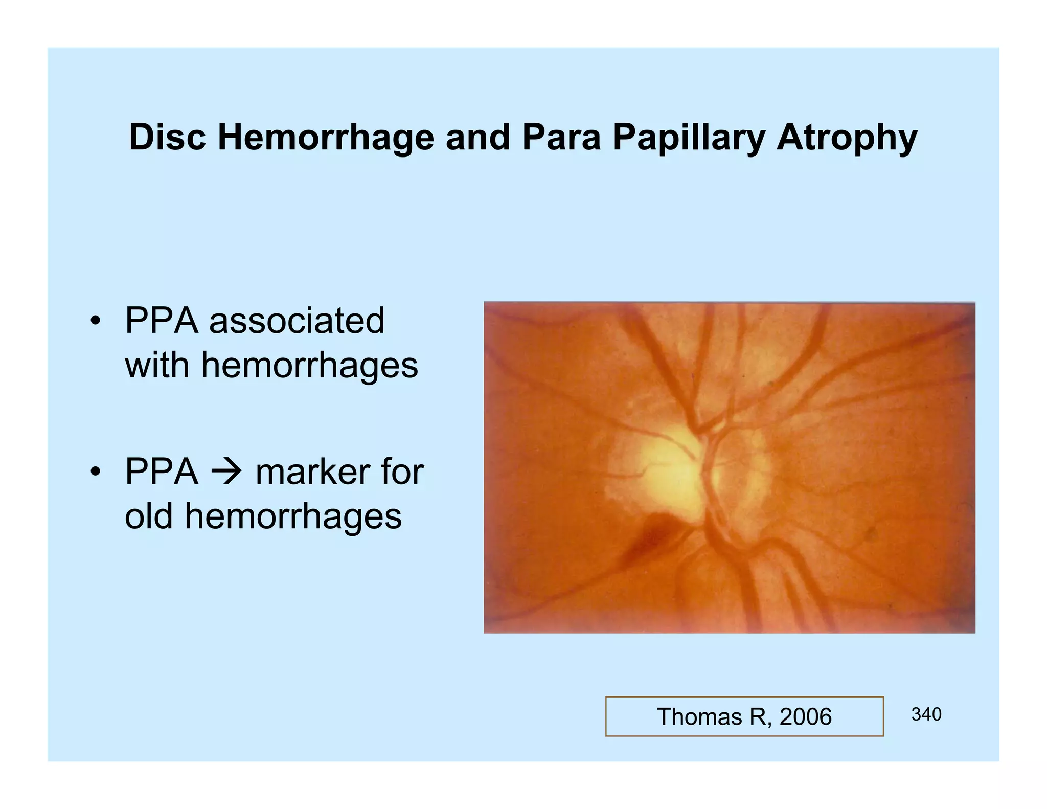
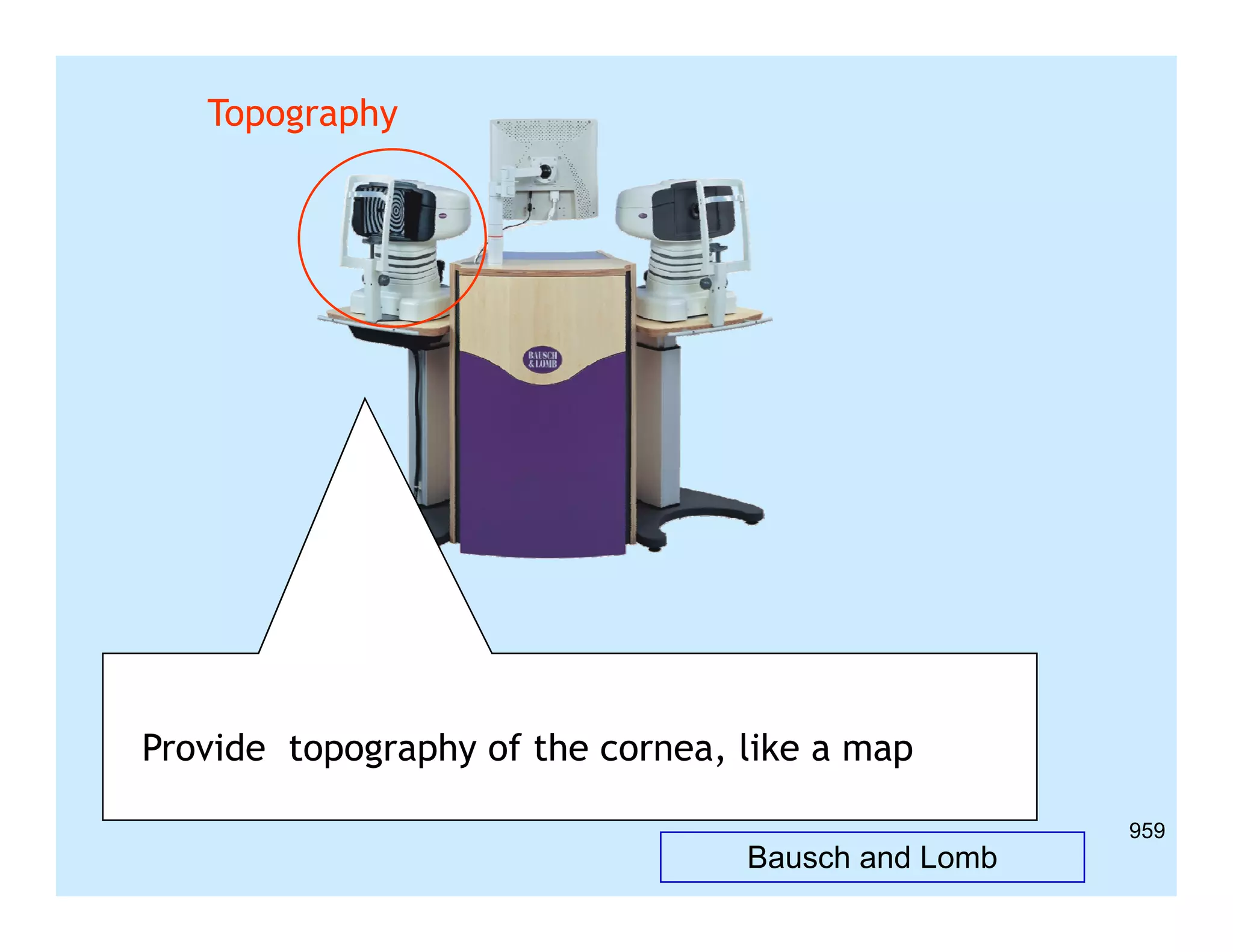
Download as PDF, PPTX


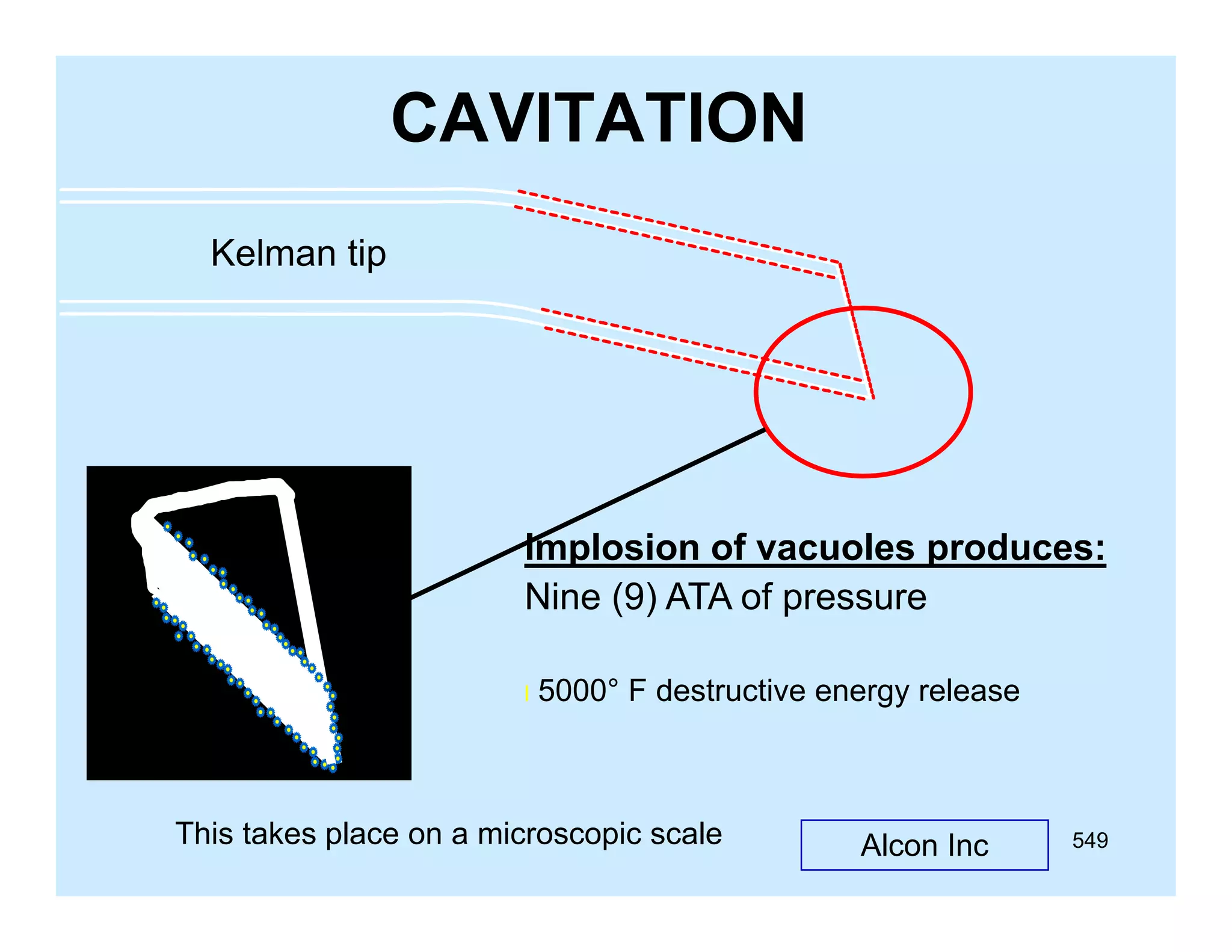


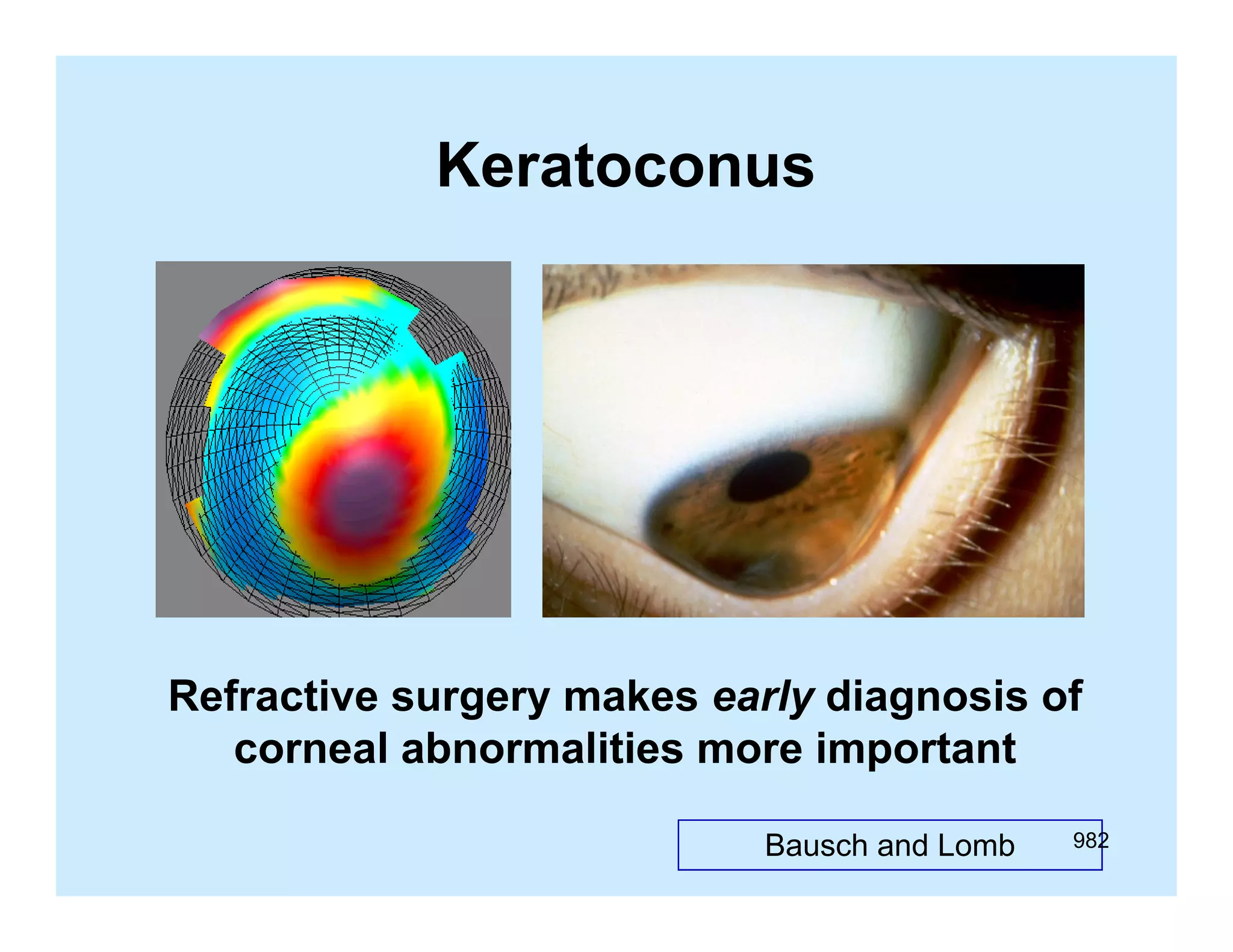


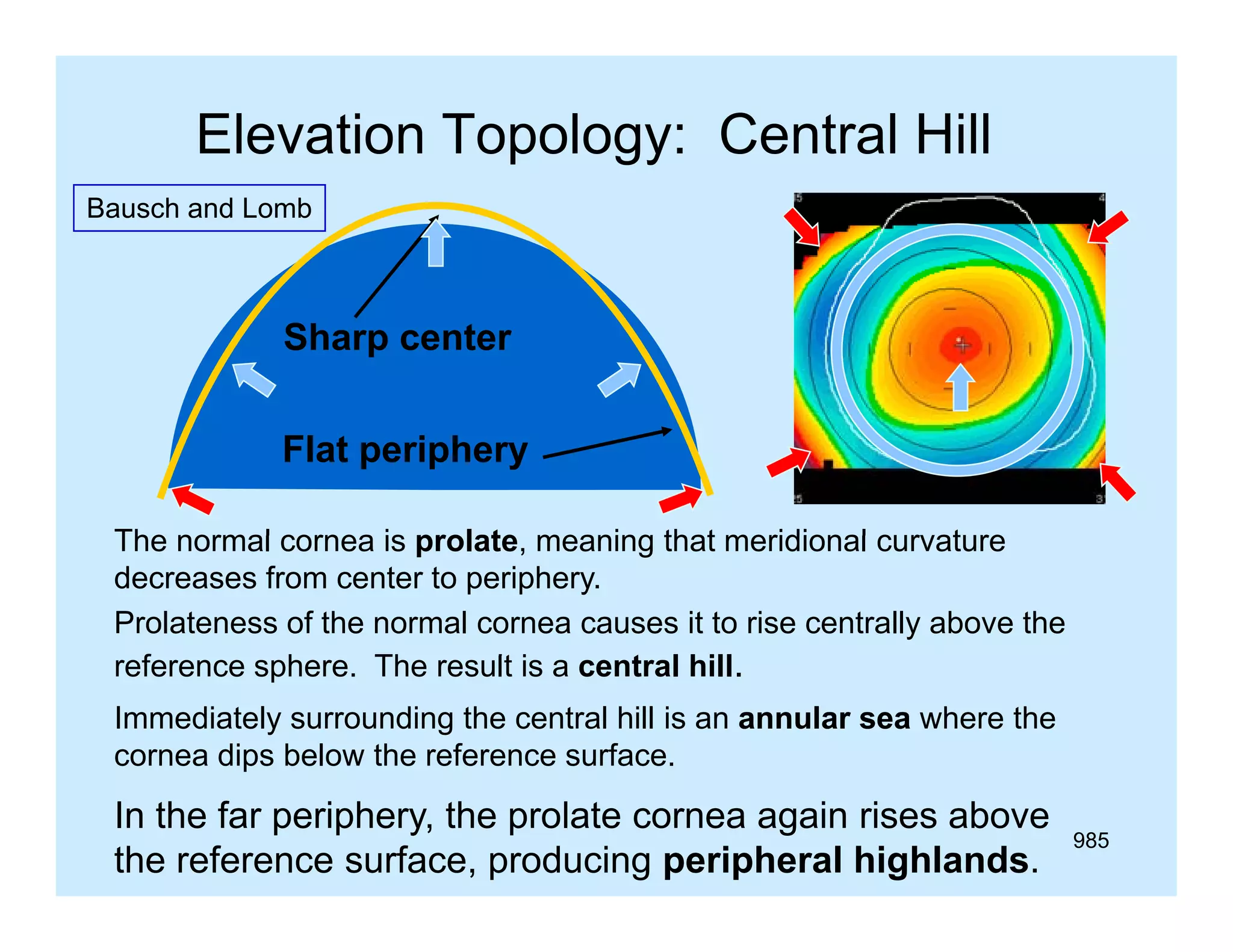
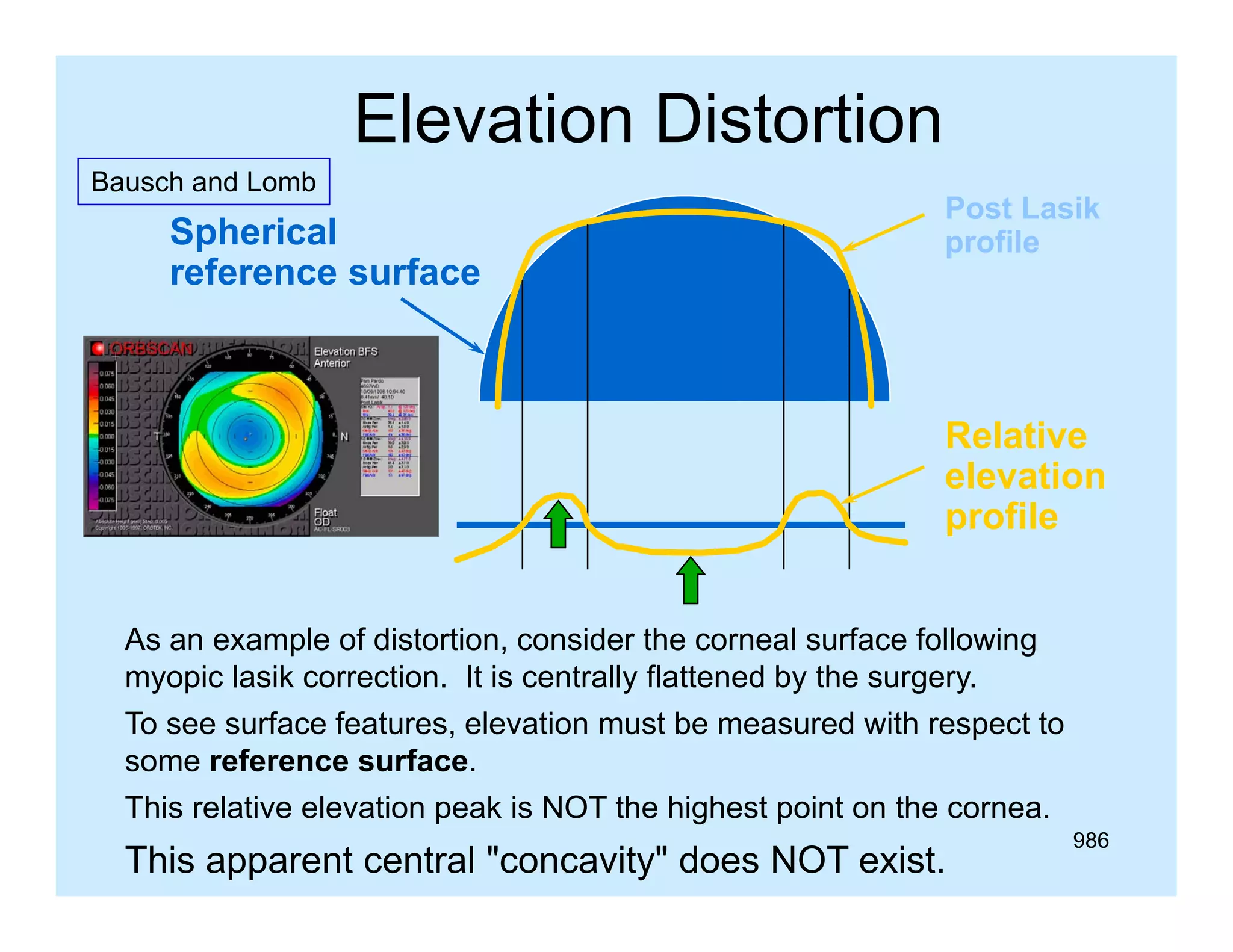


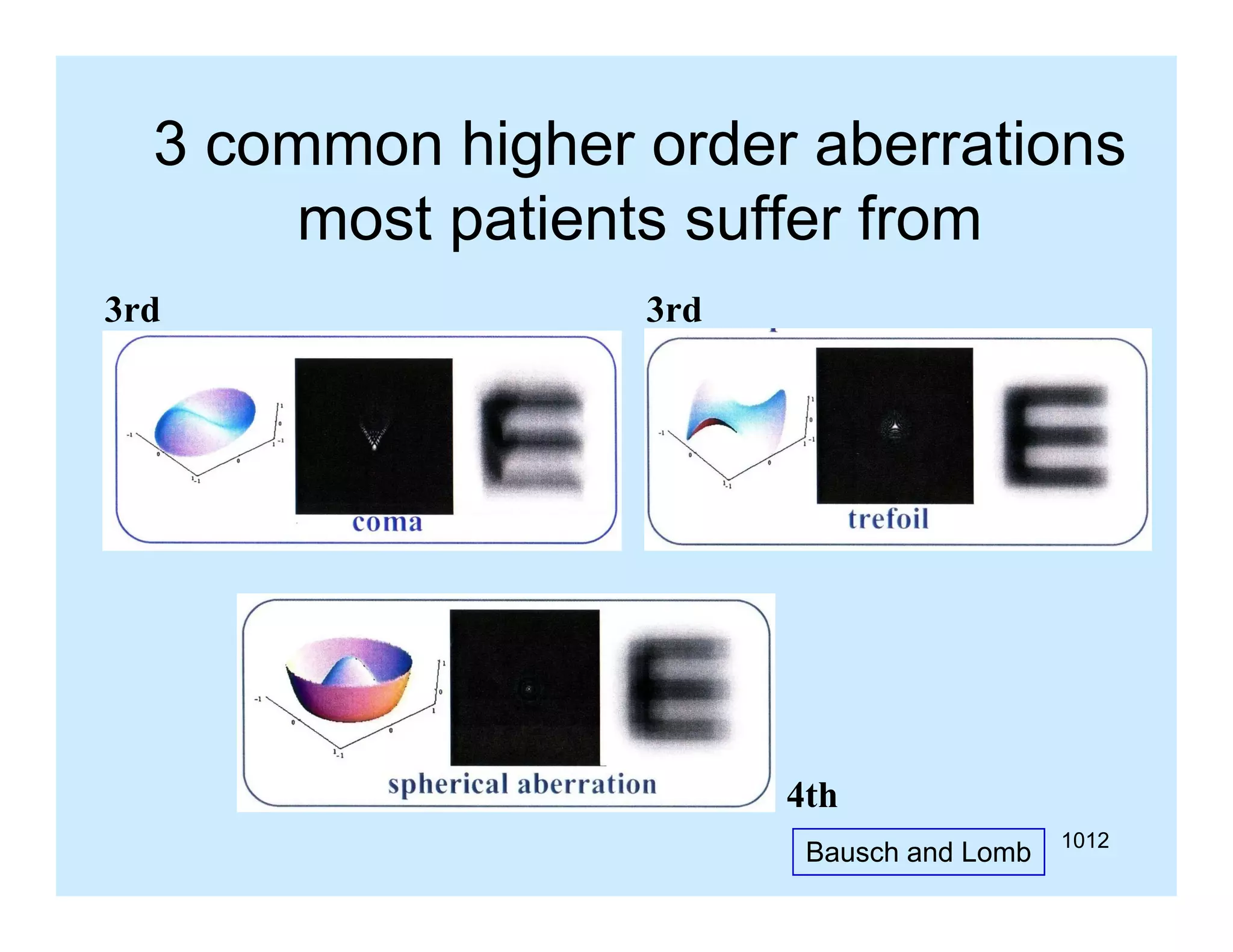

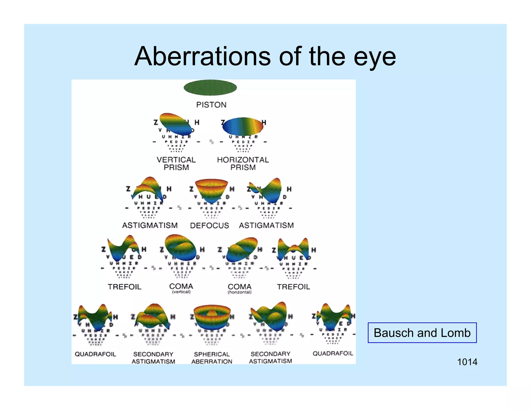

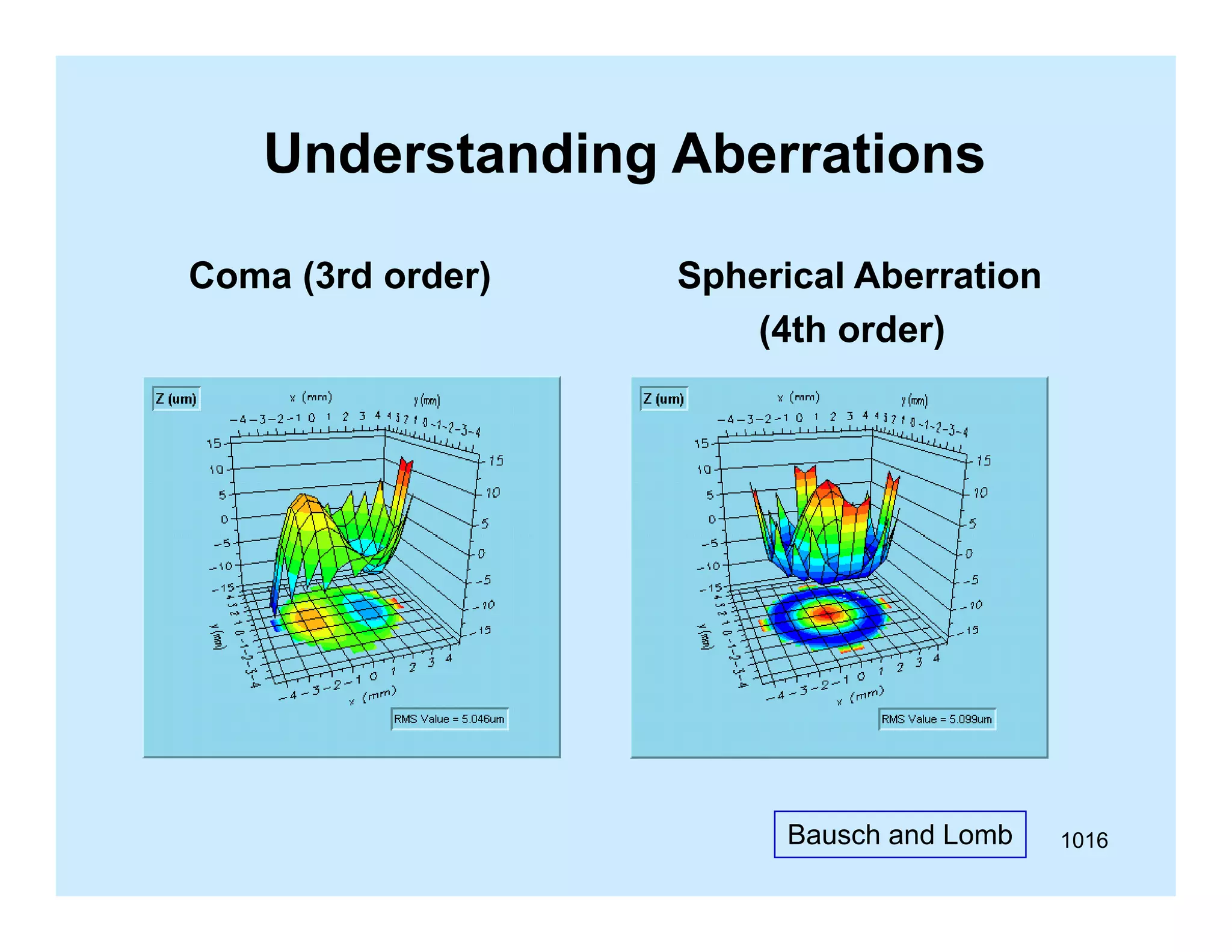

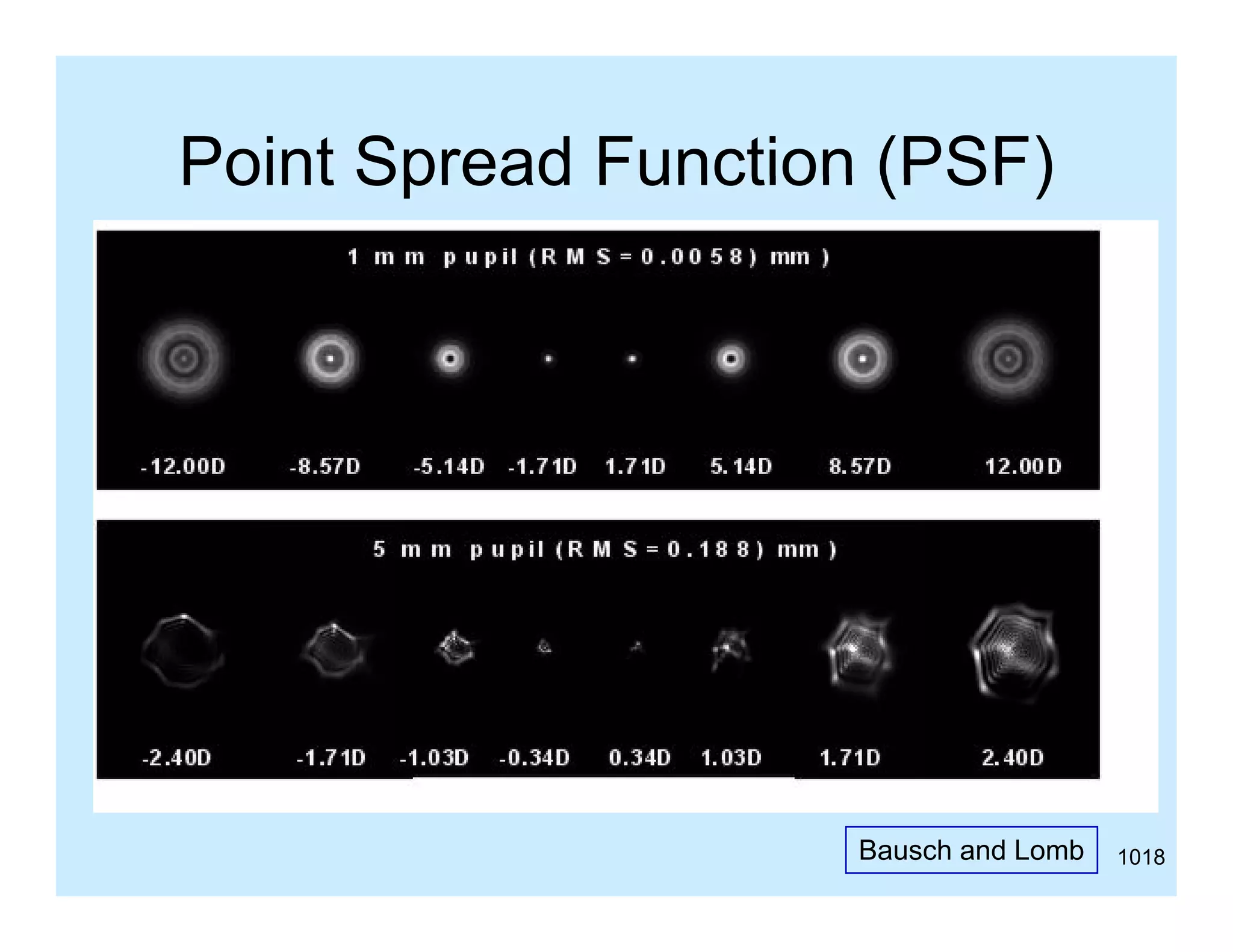


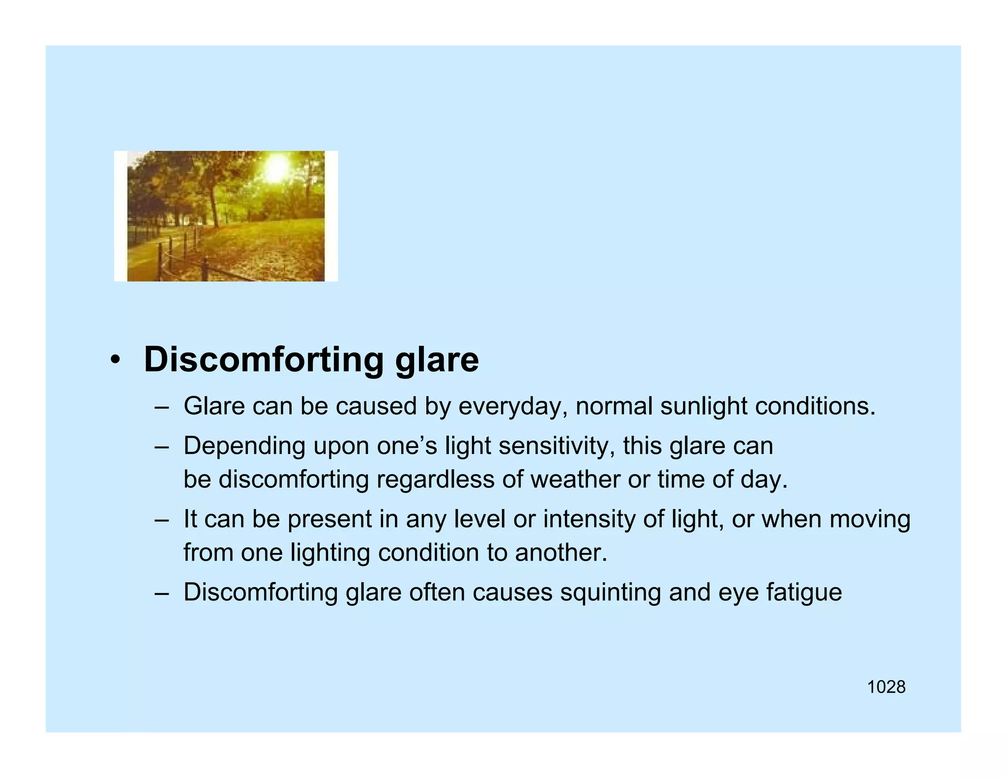


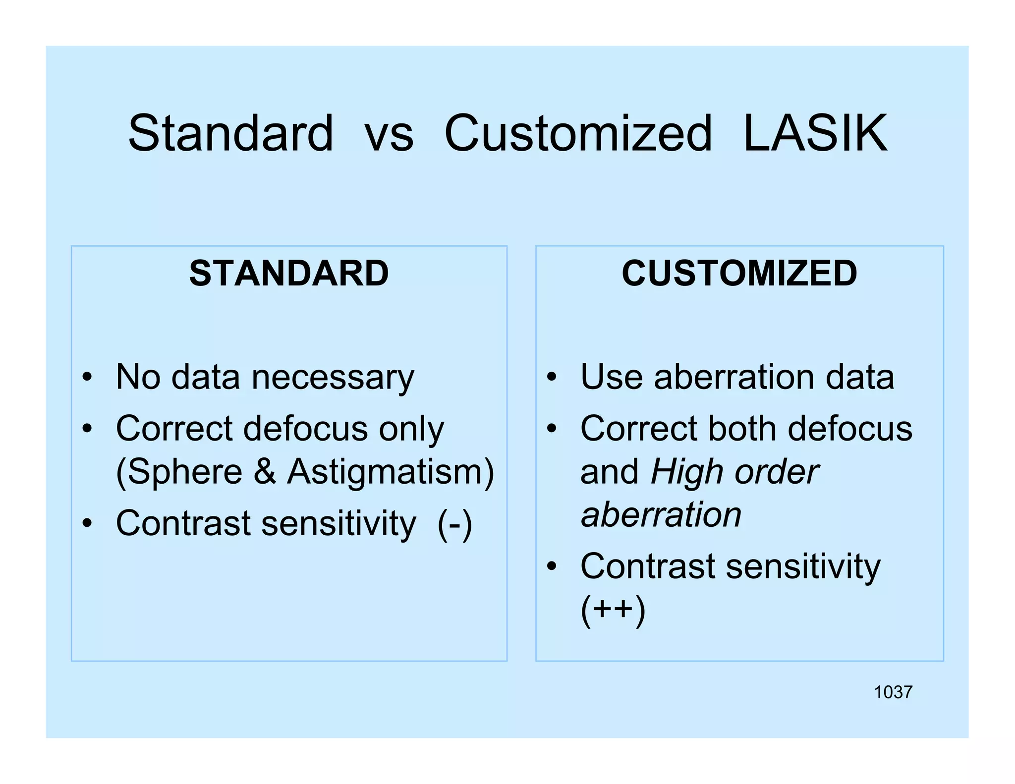
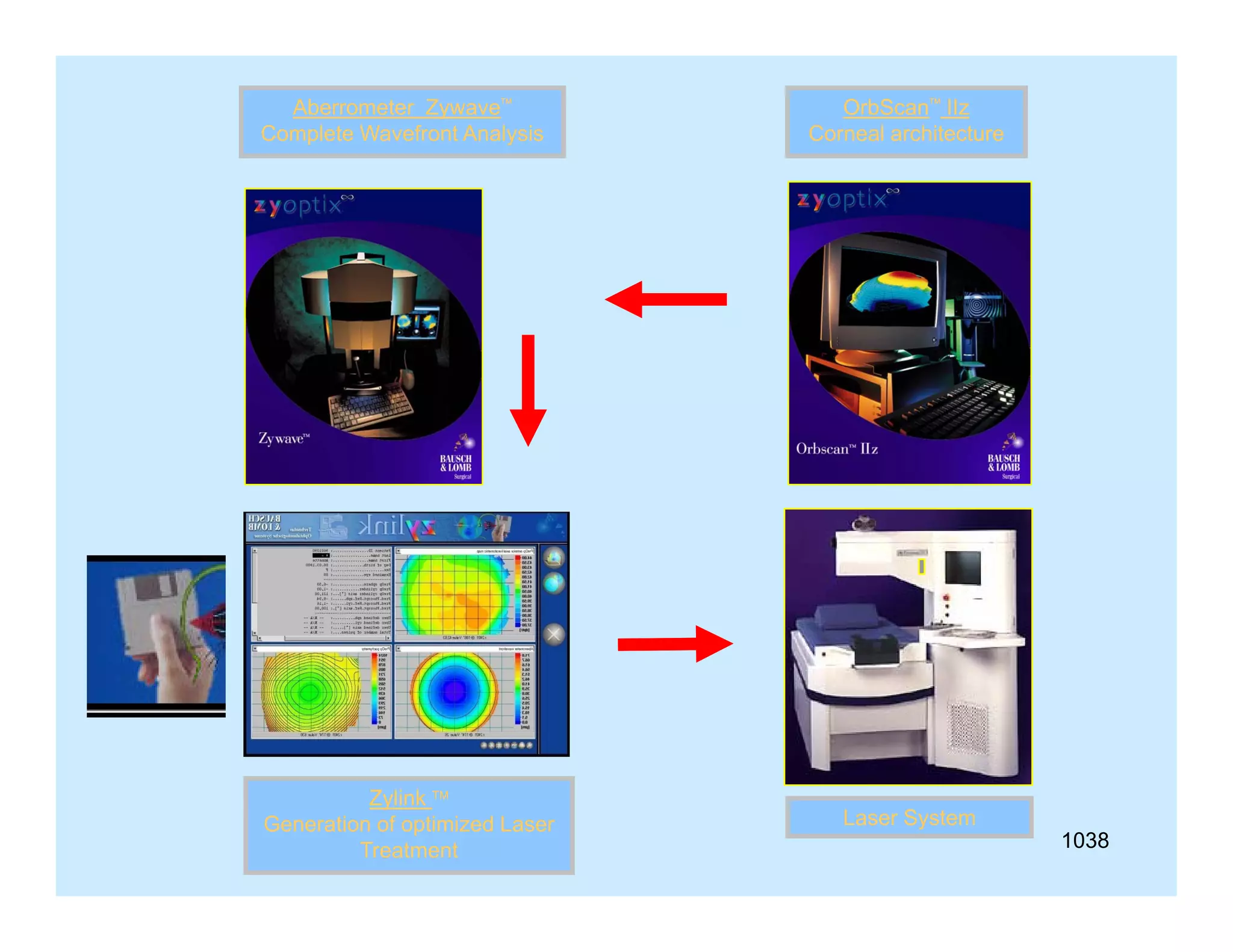
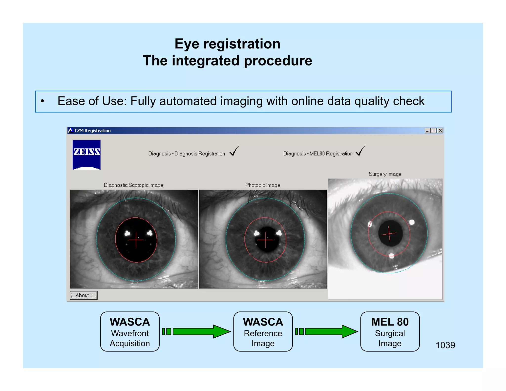


This document appears to be a slide compilation for ophthalmologists covering various topics in ophthalmology. It includes an introduction and acknowledgements section, as well as slides on topics like the spirit of Bali, visual functions and their examination, equipment used in examinations like the slit lamp and optotypes, embryology of ocular tissues, and advanced examination equipment and techniques. The compilation is meant as an educational reference for ophthalmologists.