Downloaded 183 times


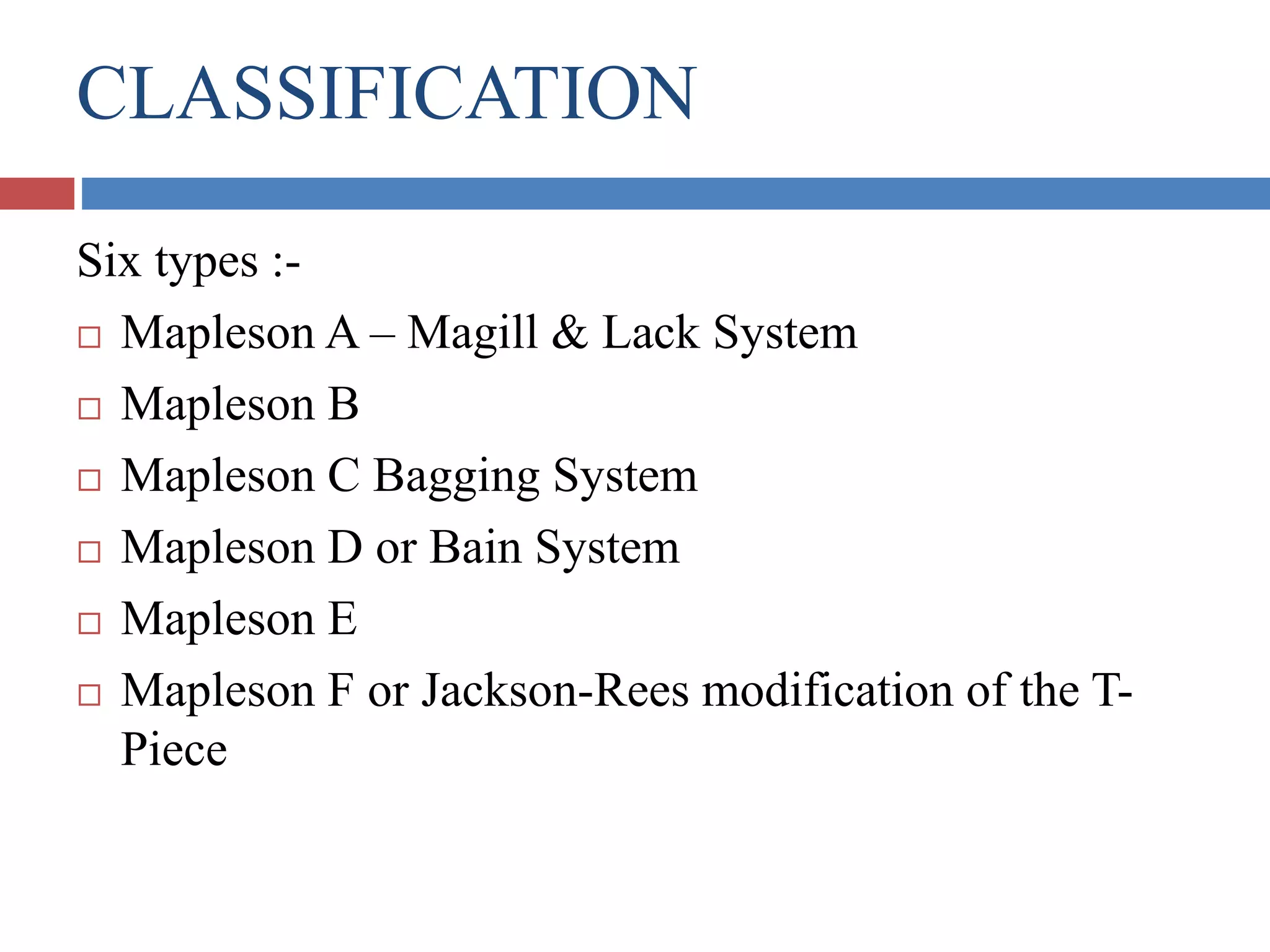


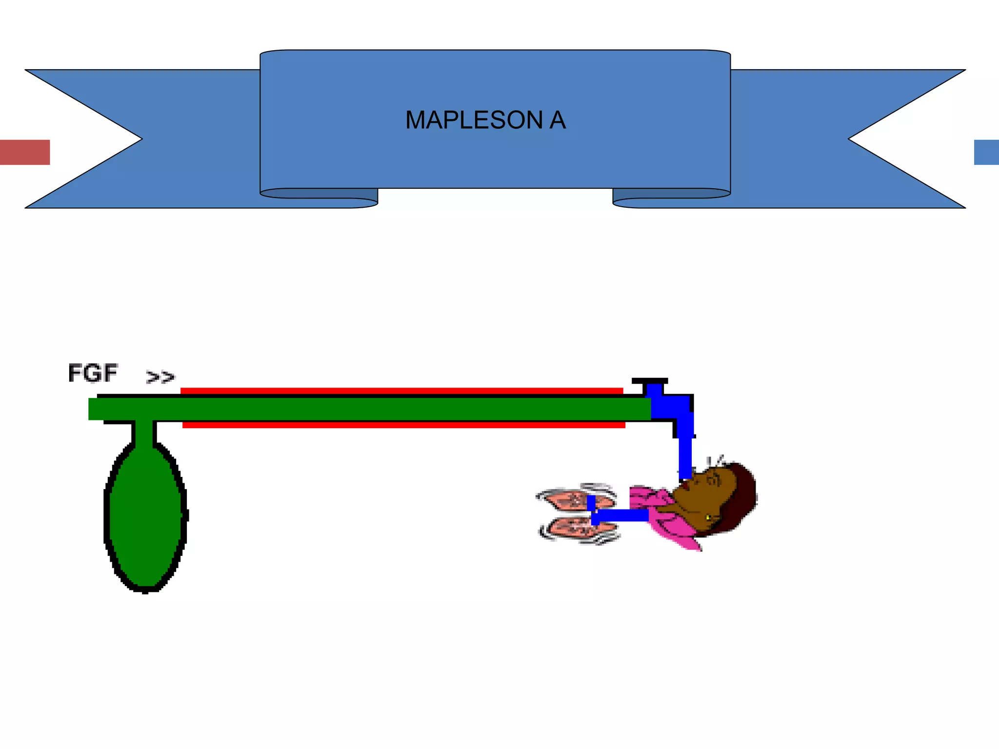


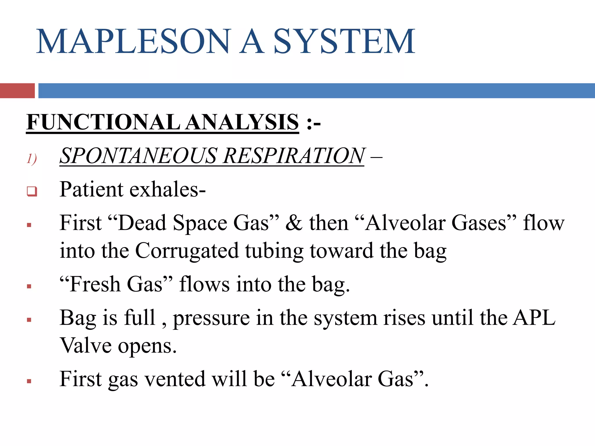
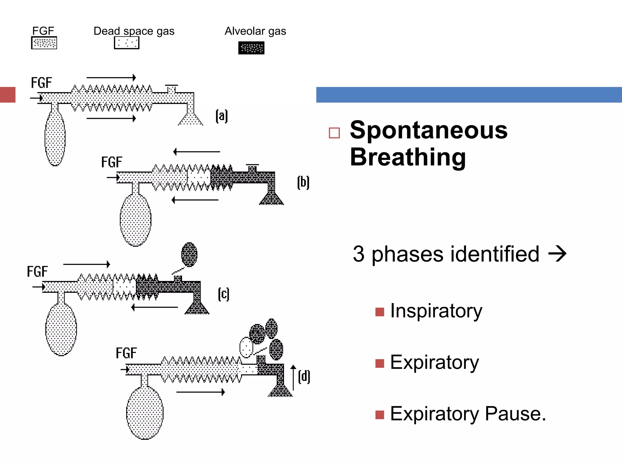
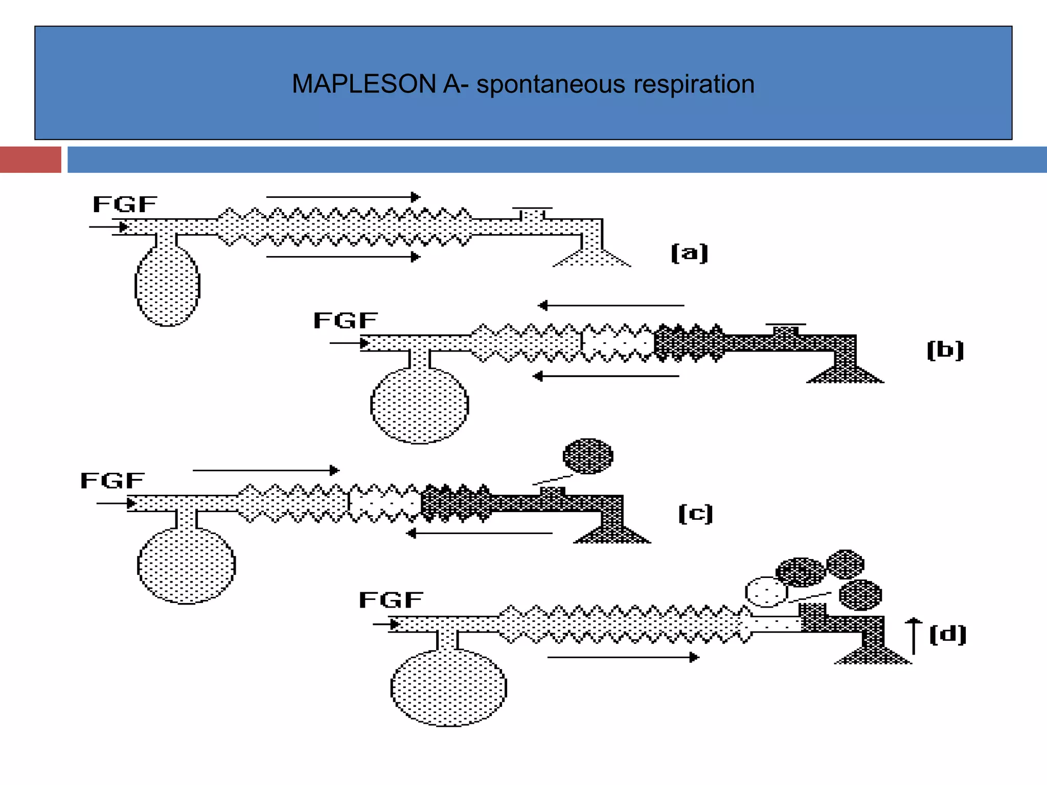


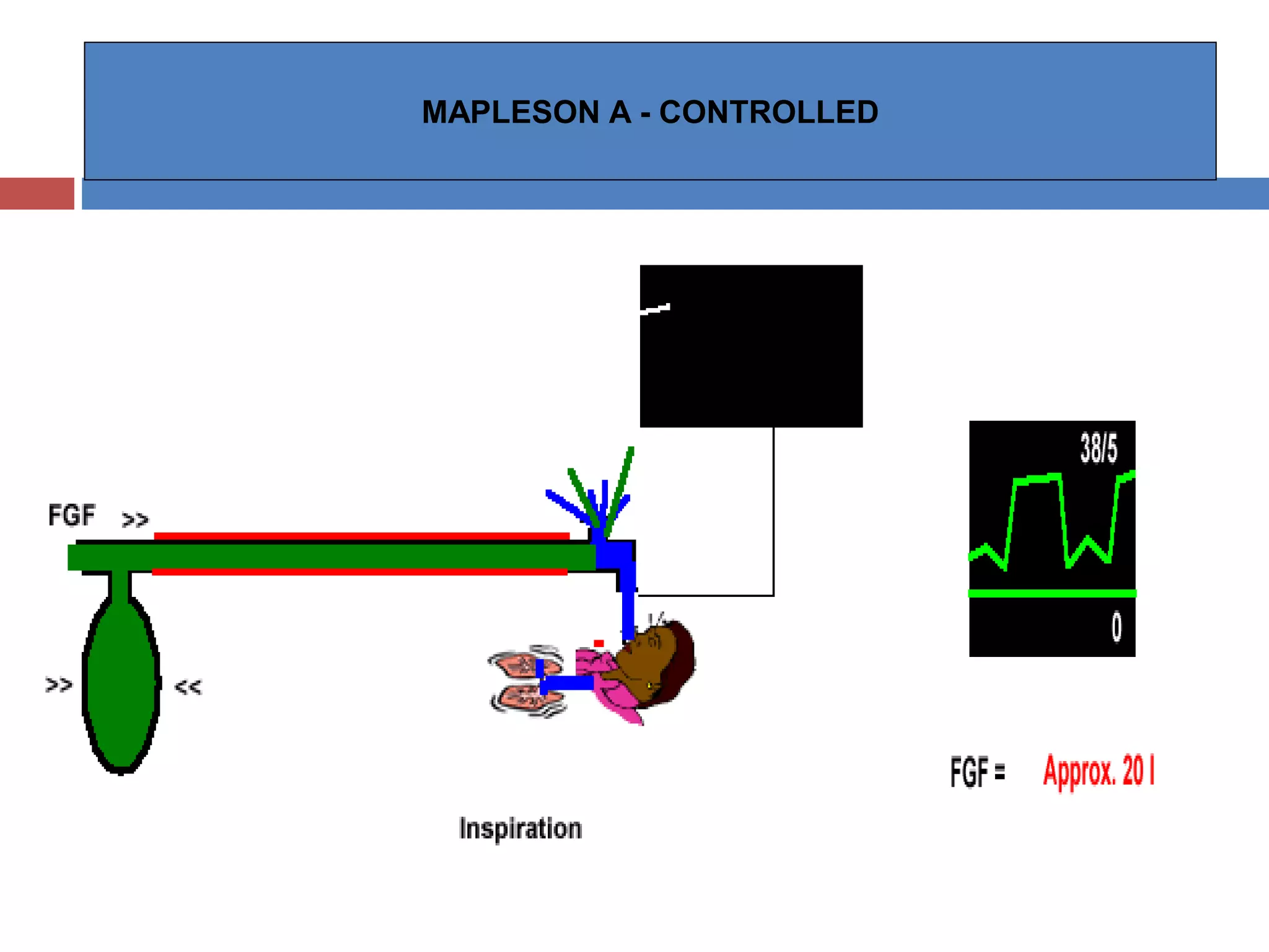


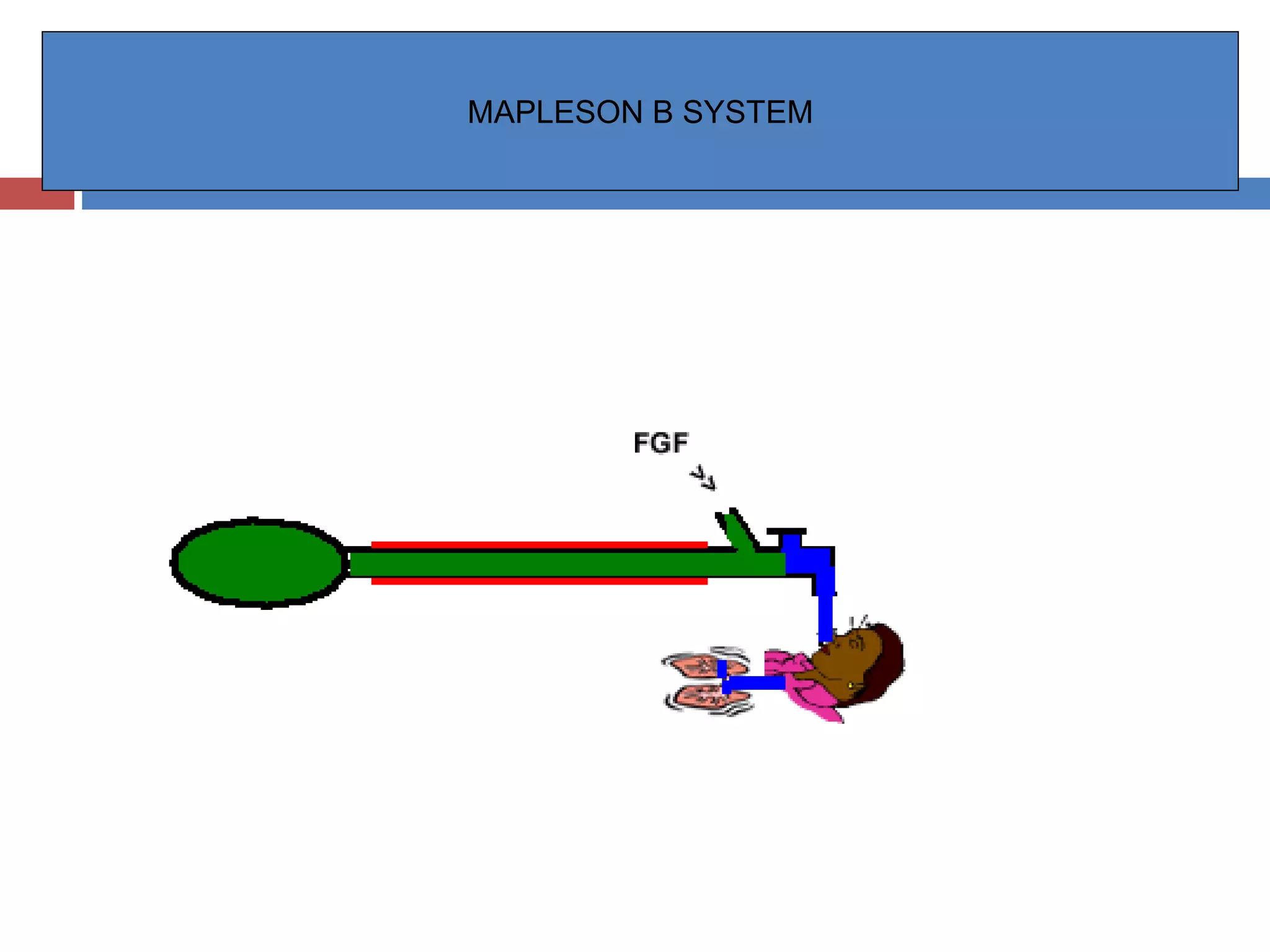


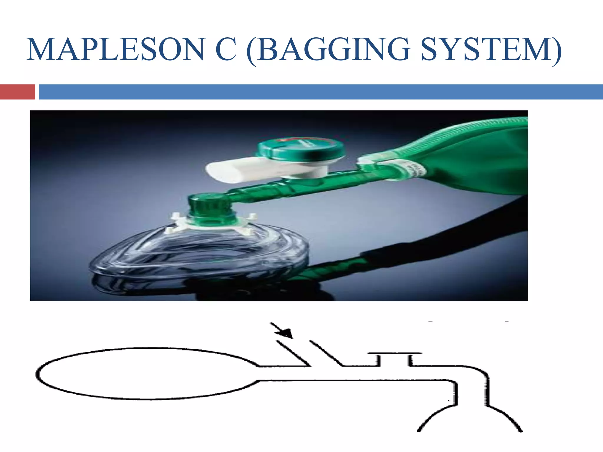
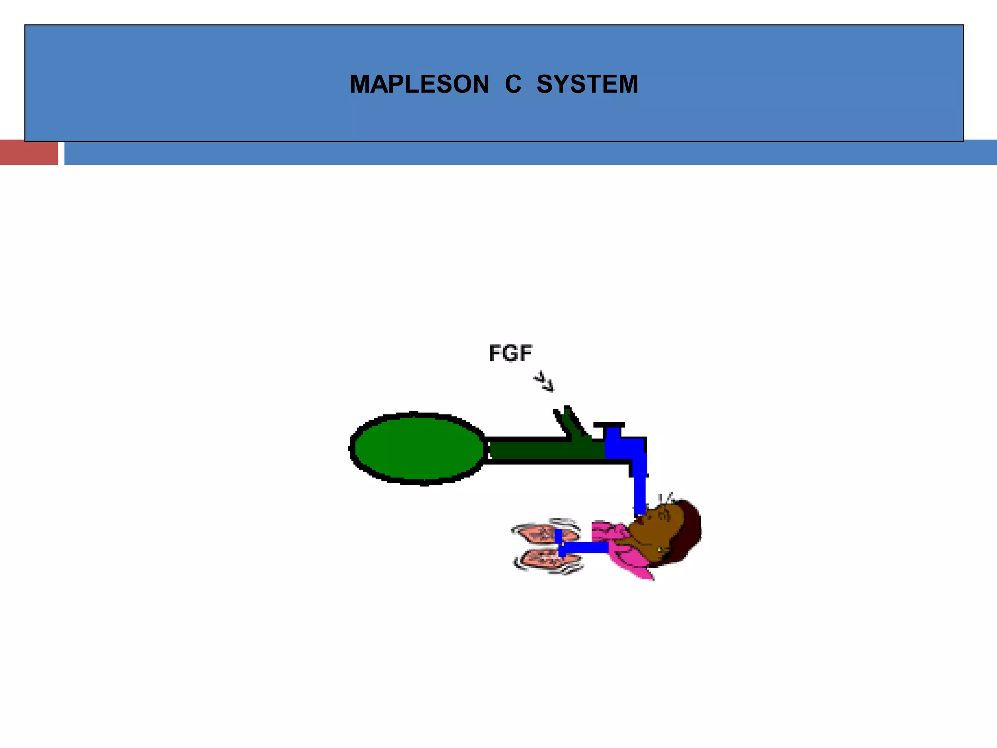
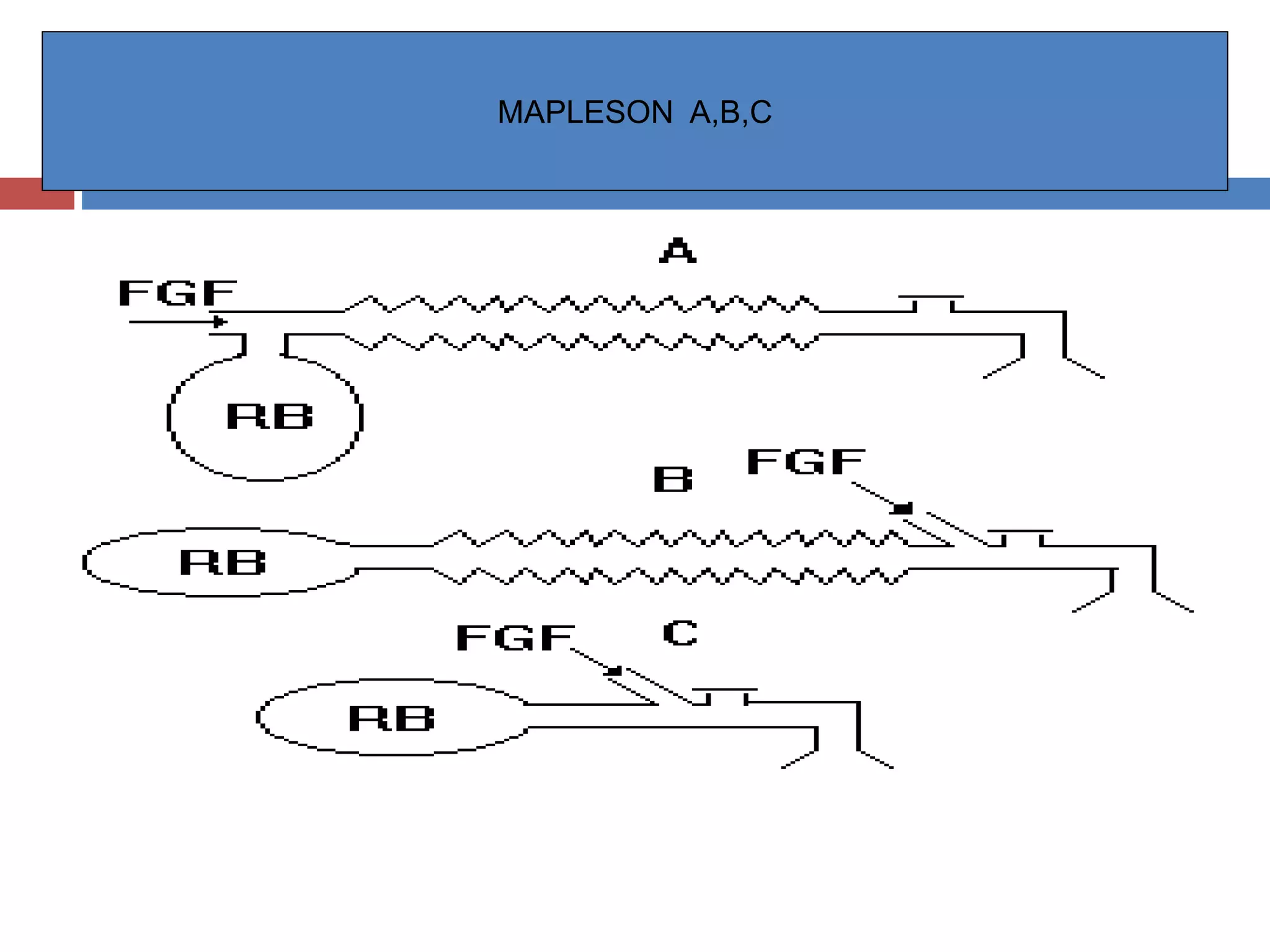


The document discusses various breathing systems used for anesthesia, including the Mapleson A-F systems. It provides details on the history, components, configurations, techniques of use, and functional analysis of each system. The Mapleson A system is described as the original system developed by Evan Magill, with fresh gas entering at the opposite end of the reservoir bag near the patient. Rebreathing occurs more readily with lower fresh gas flows. The Mapleson B and C systems have the fresh gas inlet and adjustable pressure limiting valve located near the patient end.


