Downloaded 645 times
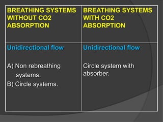
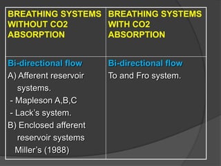
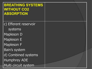
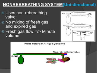
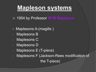
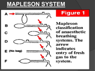
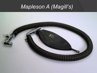
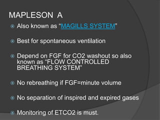
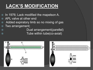

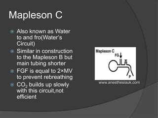
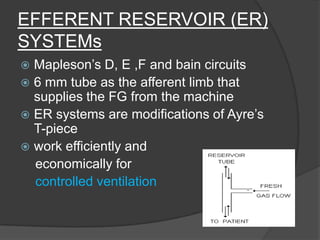
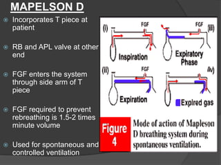
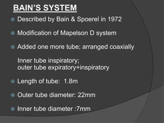
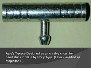
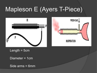
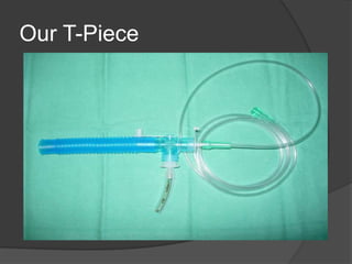
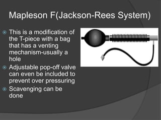
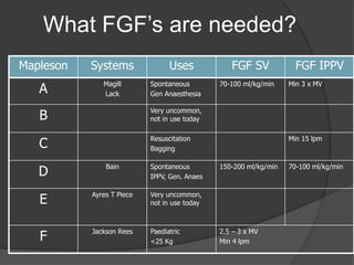
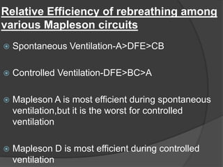

The document discusses various paediatric breathing circuits used in anaesthesia. It describes the key components and classifications of breathing circuits. The most commonly used circuits include the Mapleson A (Magill) system, which is best for spontaneous breathing but requires high fresh gas flows. The Mapleson D and Bain circuits are efferent reservoir systems that work efficiently for controlled ventilation. The Ayre's T-piece is a simple no-valve circuit designed for paediatric use. The document provides details on the construction, functioning and advantages of these different breathing circuit designs.


![5G Explained! A High Level Overview [Introduction]](https://cdn.slidesharecdn.com/ss_thumbnails/5gexplainedahighleveloverview-260119165306-cc137a3e-thumbnail.jpg?width=640&height=640&fit=bounds)