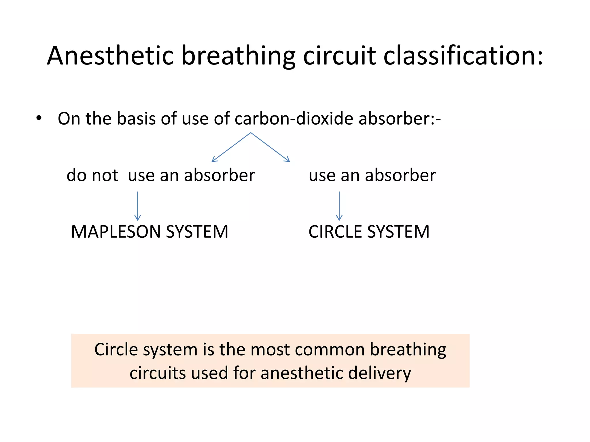
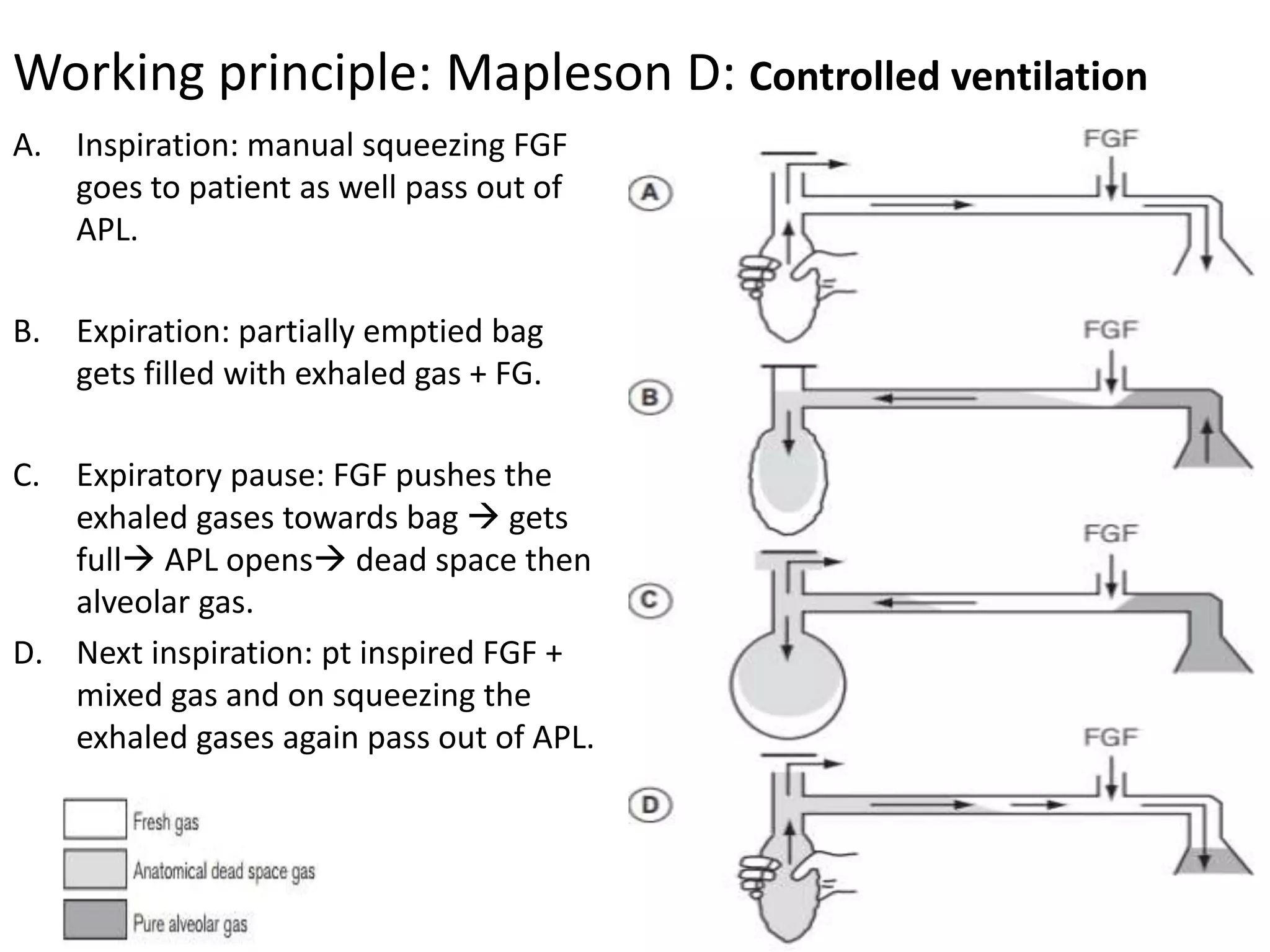
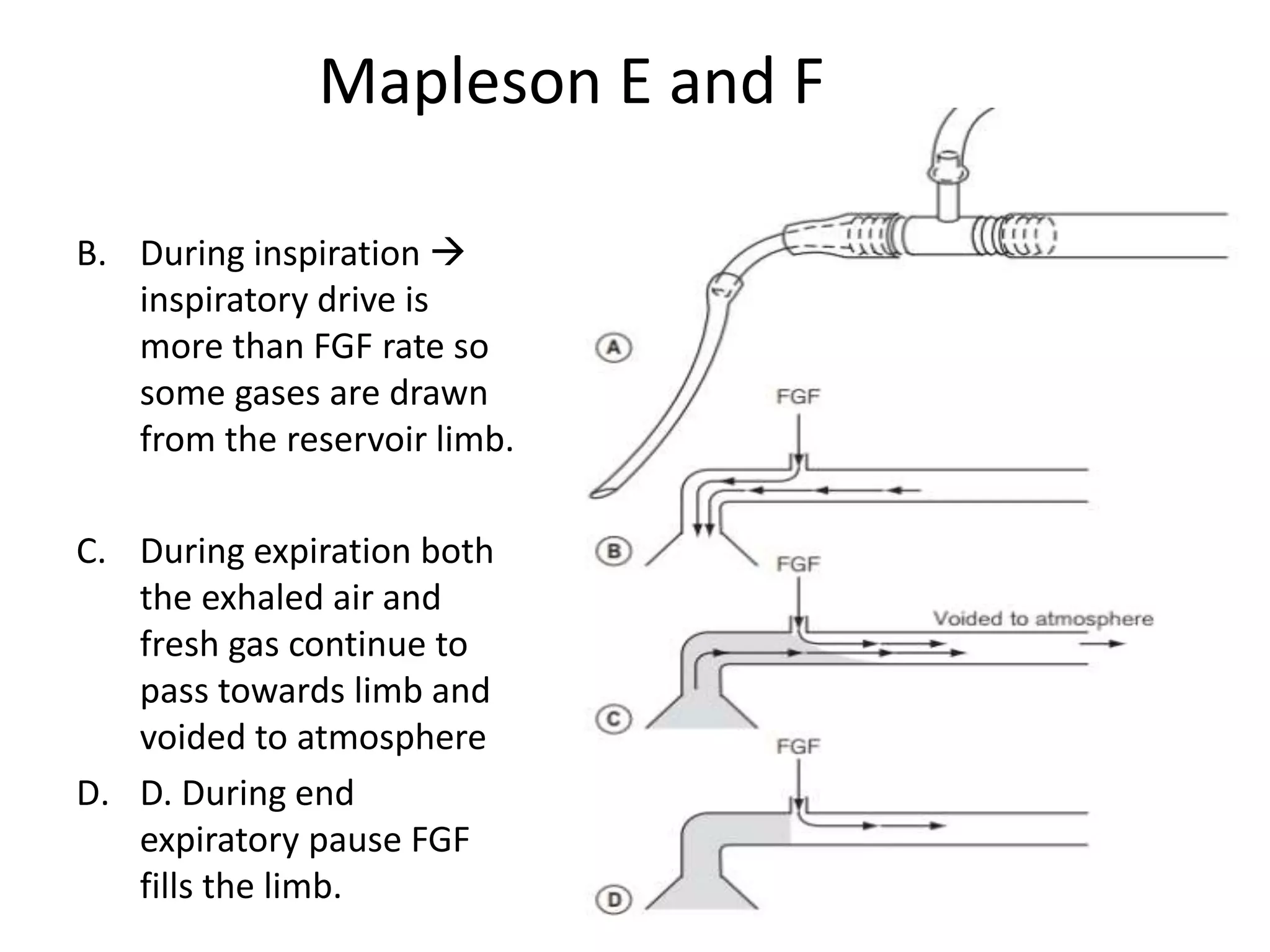
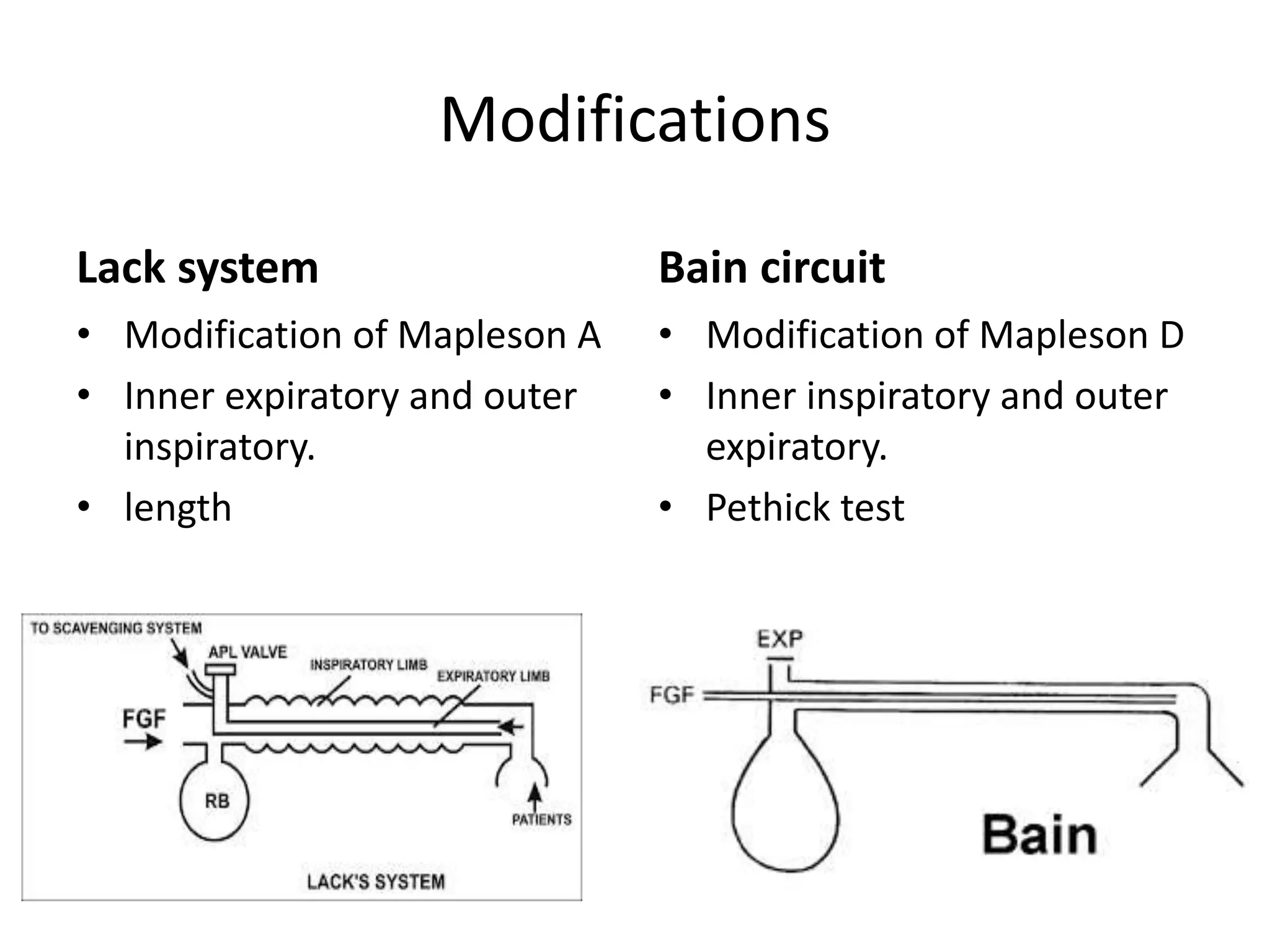
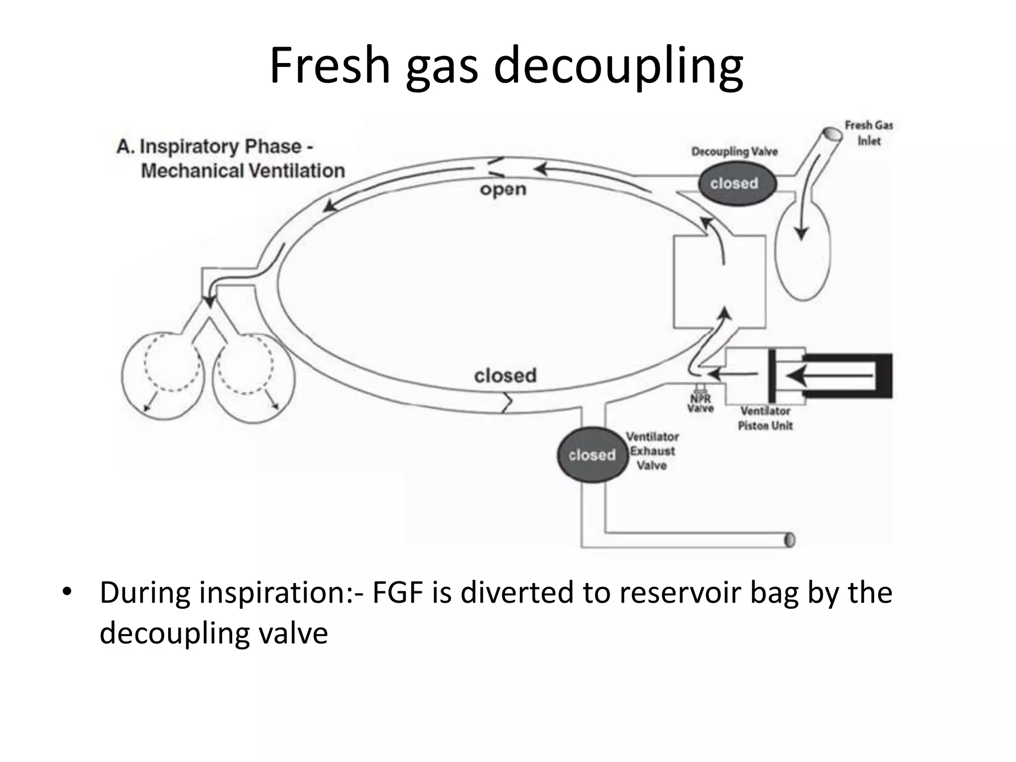
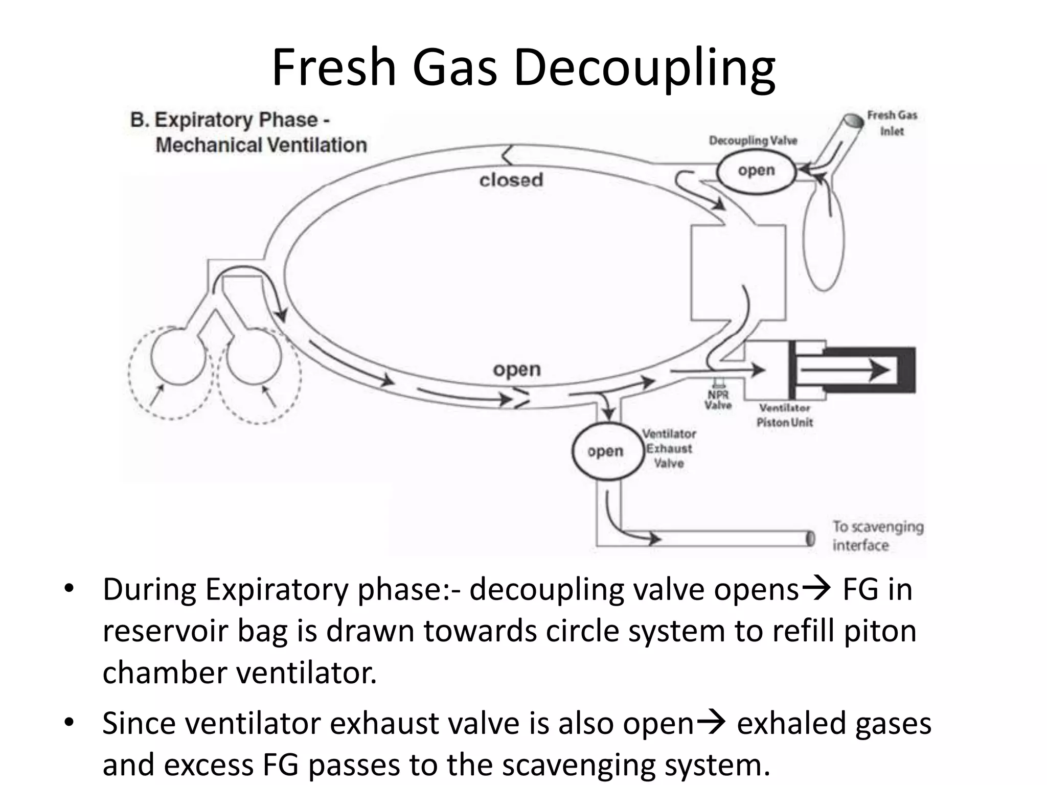
Circuits
Presenter Moderator
Dr. Pooja Lama Associate Prof. Dr. U. B. Bajracharya
Resident
Anesthesiology
Objectives
• Definitions
• History of breathing system
• Classification of breathing systems
• Working principles of breathing systems
• Components of breathing system
• Conclusion
Definition
Assembly of components which connects the patient
airway to the anaesthetic machine creating an artificial
atmosphere ,from and into which the patients breathes.
Function
• To deliver oxygen and other gases to the patient and
to eliminate carbon dioxide.
History
• Any resemblance to a breathing system was developed by
Barth (1907)
• The Mapleson A (Magill) system was designed by Sir Ivan
Magill in the 1930’s
• In 1926, Brian Sword introduced the circle system.
• Ayre’s T piece was introduced in 1937 by Phillip Ayre
• Modified by Jackson Rees into Mapleson F in 1950 by adding
500ml of reservoir bag
• Bain circuit was introduced in 1972 by Bain and Spoerel.
Classification
 McMohan in 1951
 Open  no rebreathing
 Semi closed  partial rebreathing
 Closed  total rebreathing
 Dripps classification
• Insufflation
• Open
• Semi open
• Semi closed
• Closed
Schimmelbush mask
Yankeur mask
 Conway classification
• Breathing systems with CO2 absorber
• Breathing systems without CO2 absorber
 Miller Classification
Breathing system without CO2
absorber
Breathing system with CO2
absorber
Unidirectional flow:
Non-rebreathing valve
Unidirectional flow:
Circle system with absorber
Bi-directional flow:
a) Afferent Reservoir systems
Mapleson A, B, C and Lack
b) Efferent Reservoir system
Mapleson D, E , F and Bain
c) Combined system
Humphrey ADE
Bi-directional flow:
To & Fro system
Disadvantages of insufflation and open
• Poor control of inspired gas concentration
poor control of depth of anesthesia
• Pollution of operating room with large volumes of waste gas
• Mechanical drawbacks during head and neck surgery.
Anesthetic breathing circuit classification:
• On the basis of use of carbon-dioxide absorber:-
do not use an absorber use an absorber
MAPLESON SYSTEM CIRCLE SYSTEM
Circle system is the most common breathing
circuits used for anesthetic delivery
Criteria for anesthetic breathing circuit
1. Low resistance conduit for gas flow
2. A reservoir for gas that can meet the patient’s inspiratory
flow demand
3. An expiratory port or valve to vent excess gas.
4. Have minimal apparatus dead space.
Mapleson’s classification of breathing
system
• Mapleson in 1954 described and analyzed five different
breathing circuits. (A, B, C, D, E)
• Willis in 1975 described the F system.
• Similar to circle breathing system that they accept a fresh gas
flow, supply sufficient volume of gas and eliminate carbon-
dioxide.
• Differ from circle system that they have bidirectional flow and
do not use an absorber.
Components of Mapleson
• Patient end to a facemask or endotracheal tube
• Breathing corrugated tubes
• Fresh gas inlet
• Adjustable pressure limiting valve
• Reservoir bag
Different types of Mapleson
Three distinct functional groups can be seen:
Functional groups Gas stored in
reservoir bag
Named as
A Fresh Gas Afferent reservoir
system
BC Mixed inspired
and expired gas
Junctional
reservoir system
DEF Mixed expired gas Efferent reservoir
system
Relative efficacy of Mapleson system
 During spontaneous ventilation:
A>DFE>CB
 During controlled ventilation:
DFE>BC>A
Mapleson A
• Mapleson A is also called as Magill circuit
• It is best for spontaneous ventilation.
• Modification of Magill circuit is called as Lack’s circuit.
• Mapleson A has a corrugated breathing hose of length 110 cm
with an internal volume of 550ml.
Working principle: Mapleson A:- Spontaneous ventilation
A. Breathing bag fills with
FGF in first inspiration.
B. Pt inspires the gases so
the reservoir bag
becomes partially empty
C. Exhale:- gases from both
ends enter bag and once
it is full the exhaled gases
pass out through APL
valve
D. End-expiratory pause:
FGF now drives the
exhaled gases out.
A. Inspiration: manual squeezing
though APL valve is closed some
of FGF will go out.
B. Since bag is completely empty,
now on expiration the exhaled
gases will reach the bag and get
mixed. But bag is not yet full
enough to open the APL valve.
C. On next inspiration: on
squeezing APL valve opens
and exhaled gases pass out as
well they are inhaled so
rebreathing occurs.
Working principle: Mapleson A:- Controlled ventilation
Mapleson B and C
• Mapleson B:- FGF should be 2-
2.5 times the minute
ventilation.
• Mapleson c (Bagging system)
A. Inspiration: FGF fills the bag and
hose and as respiratory rate is
higher than FGF rate so the bag
get emptied.
B. Expiration: exhaled gas get mixed
with FGF and reach bag.
C. When bag is full: exhaled gases
pass out of APL valve, first
anatomical dead space then
alveolar gas.
D. Next inspiration: rebreathing
occurs.
Working principle: Mapleson D:- Spontaneous ventilation
A. Inspiration: manual squeezing FGF
goes to patient as well pass out of
APL.
B. Expiration: partially emptied bag
gets filled with exhaled gas + FG.
C. Expiratory pause: FGF pushes the
exhaled gases towards bag  gets
full APL opens dead space then
alveolar gas.
D. Next inspiration: pt inspired FGF +
mixed gas and on squeezing the
exhaled gases again pass out of APL.
Working principle: Mapleson D: Controlled ventilation
Mapleson E and F
B. During inspiration 
inspiratory drive is
more than FGF rate so
some gases are drawn
from the reservoir limb.
C. During expiration both
the exhaled air and
fresh gas continue to
pass towards limb and
voided to atmosphere
D. D. During end
expiratory pause FGF
fills the limb.
Modifications
Lack system
• Modification of Mapleson A
• Inner expiratory and outer
inspiratory.
• length
Bain circuit
• Modification of Mapleson D
• Inner inspiratory and outer
expiratory.
• Pethick test
Bain circuit
.
 Coaxial circuit and modification of Mapleson D
 Outer tube 22 mm diameter.
 1.8 m long
 Fresh gas flow to patient end via thinner coaxial inside the
expiratory tube
 Fresh gas inflow rate necessary to prevent rebreathing is
2.5 times minute ventilation
Isopleth
• Vf- Fresh gas flow rate
ml/kg/min
• Ve- minute ventilation
ml/kg/min
 When FGF is high
PACO2 becomes
ventilation
dependent.
 When minute
volume exceeds the
FGF PACO2 is
dependent on FGF.
Advantages of Bain circuit
• Lightweight, convenient, easily sterilized and reusable.
• Very low resistance to breathing.
• Scavenging of gases from the expiratory valve is facilitated
because the valve is located away from the patient.
• Exhaled gases in the outer reservoir tubing add warmth to the
inspired fresh gases by countercurrent heat exchange.
Disadvantages of Bain circuit
o Unrecognized disconnection and kinking of the inner
fresh gas tube.
o An obstructed antimicrobial filter positioned
between the Bain circuit and the endotracheal tube
can result in increased resistance in the circuit.
o High flow gas rate  wastage of gas.
Pethick
test
Outer tube is
transparent
Test for Bain’s circuit
Pethick test Foex Crempton Smith test
Close the APL valve and allow
reservoir bag to fill completely
Now press oxygen flush
Reservoir bag collapses if inner
tube is intact
Because oxygen delivered at
high flow through inner tube
will drag all the air present in
the outer tube due to its
venturi effect.
Close the APL valve and turn on
oxygen at 2 L/minute
End of inner tube is occluded
If inner tube is intact then
bobbin will descend slightly
Once released it will ascend to
its original place.
Required fresh gas flow
Advantages of Mapleson system
 Equipment is simple, inexpensive and rugged.
 Variations in minute volume affect end tidal CO2 less than
circle system.
 Are lightweight and not bulky.
 Easy to position conveniently.
 Changes in fresh gas concentrations result in rapid changes in
inspiratory gas composition.
Disadvantages of Mapleson system
 These system require high gas flows.
 Because of high fresh gas flow, inspired heat and humidity
tend to be low.
 In mapleson A, B and C the APL valve is located close to
patient , where it may be inaccessable to the user.
 Mapleson E and F are difficult to scavange.
Circle system
Circle system
• It is so named because :-
 it allows circular,
 unidirectional gas flows
 Facilitated by unidirectional valves
It must allow for spontaneous ventilation, manual
ventilation and positive pressure ventilation.
Circle system
Three Essential factors
• There should be:-
 Two unidirectional valves on either side of reservoir bag and
canister.
 Pop off valve or APL valve should be positioned in the
expiratory limb only.
 The Fresh Gas Flow should enter the system proximal to the
inspiratory unidirectional valve.
Low Flow Anesthesia
• To enhance oxygen and anaesthetic uptake and the excretion
of nitrogen (N2), a high FGF is recommended at the start of an
anaesthetic.
• When clinically desirable concentrations are reached,
the FGF can be reduced, to a basal metabolic oxygen
consumption rate of approximately 250 ml min−1.
• Hence in circle system, low flow upto 250ml/min to
500ml/min can be administered.
Advantage of circle system
1. Maintenance of relatively stable inspired gas concentrations
2. Conservation of respiratory moisture and heat
3. Elimination of carbon dioxide
4. An economy of anesthetic gases resulting:-
 from rebreathing
 as FGF could be reduced to as low as 250-500ml of oxygen
5. Prevention of operating room pollution.
Disadvantage of circle system
1. Leaks and disconnections
2. Misconnections
3. Occlusion
4. Malfunction of unidirectional valves
Components of circle system
• Fresh gas inflow source
• Inspiratory and expiratory unidirectional valves
• Inspiratory and expiratory corrugated tubes
• Y piece
• Overflow or adjustable pressure limiting valve
• Reservoir or breathing bag
• Canister containing carbon-dioxide absorbent.
Unidirectional valves.
• Essential element .
• Incompetence is one the most common problem
Adjustable pressure limiting valve
• It is operator-adjustable relief valve that vents excess
breathing circuit gases to the scavenging system.
• Other common names are
 “pop off” valve and
 pressure relief valve.
• Types:- 1. variable- resistor or variable-orifice type
2. pressure-regulating type Modern machines
APL valve with inbuilt overpressure safety
devices
A. When unscrewed:- Outer valve
opens when exhaled gases
create a pressure of 1.5cm H20
B. Valve is closed (fully screwed)
C. Valve is fully screwed so an
excess pressure needed to
open the valve.
 At 30 cm H2O valve begins
to open.
 At 60-70 cm H2O valve is fully
open.
Anesthetic reservoir bag
 Breathing Bag.
 Capacity:- 500ml, 1L or 2L.
 Pressure standards:-
Minimal pressure 30 cm H2O
Maximal pressure  60 cm H2O
Functions of reservoir bag
 Serves as reservoir for exhaled gases and excess fresh gas.
 Means of delivering manual ventilation
 Serves as visual and tactile means of monitoring spontaneous
breathing effort
 Partially protecting the patient from excessive positive
pressure on inadvertent closure of APL valve.
Fresh gas decoupling
• During inspiration:- FGF is diverted to reservoir bag by the
decoupling valve
Fresh Gas Decoupling
• During Expiratory phase:- decoupling valve opens FG in
reservoir bag is drawn towards circle system to refill piton
chamber ventilator.
• Since ventilator exhaust valve is also open exhaled gases
and excess FG passes to the scavenging system.
Corrugated breathing circuit tubing
• The hoses should have a diameter that provided low
resistance to gas flow to provide laminar flow.
 Adults:- 22mm
 Pediatrics:- 15 mm
• Should be flexible so that kinking does not occur.
• Corrugated so as to adjust the length of tube.
• Light weight.
Carbon-dioxide absorbers
• Ideal carbon-dioxide absorbents:-
 Lack of reactivity with common anesthetics
 Absence of toxicity
 Low resistance to airflow
 Minimal dust production
 Small cost
 Ease of handling
 High efficiency carbon dioxide absorption
Absorber canister
• Transparent  to monitor the absorbent for its presence and colour.
• The absorbent should be changed when the colour change is about
50 to 70%.
Chemistry of Absorbents
• Most commonly used is Soda-Lime
Absorbent Ca(OH)2 H2O NaOH KOH
Soda lime 80% 16% 3% 2%
1. CO2 + H2O H2CO3
2. H2CO3 +2HaOH (KOH) Na2CO3 (K2CO3) +H2O + heat
3. Na2CO3 (K2CO3) + Ca(OH)2 CaCO3 + 2NaOH(KOH) +Heat
Some of carbon dioxide abosorbers:
Absorbent Ca(OH)2 % LiOH% H2O% NaOH% KOH% Other%
Classic
soda lime
80 0 16 3 2 --
Baralyme 73 0 11-16 0 5 11 Ba(OH)
New soda
lime
73 0 19 <4 0 --
Spiralith 0 95 0 0 0 <5
Polyethylene
Indicators
• Fresh soda lime has pH = 12.
 Decreases as CO2 is absorbed.
 Indicators:-
 White Soda lime contains ethyl violet, critical pH = 10.3;
purple
 Pink Soda lime contains phenolphthalein, critical pH= 7.
colourless.
Carbon dioxide removal capacity
• 100 grams of soda lime granules absorb around 14-23 liters of CO2.
• If completely reacted:-
A pound of calcium hydroxide
has the capacity to absorb 0.59
lb of carbon dioxide
A pound of Lithium
hydroxide has the ability to
absorb 0.91 lb of carbon
dioxide.
Factors affecting carbon dioxide
removal capacity
1. The amount of surface area of the absorbent to which the
exhaled gas is exposed,
2. The intrinsic capacity of absorbent to remove carbon dioxide,
3. The amount of functionally intact absorbent remaining in the
absorber.
Smaller the granule size greater the surface area so more absorption.
BUT
the airflow resistance is increased
Size of granule
• 4-8 mesh size  is the size at which absorptive surface area
and resistance to flow are optimized.
• Mesh size refers to the number of openings per linear inch in
a seive through which the granular particles can pass.
Problems with absorbents
A. Formation of potentially harmful products:-
1. Compound A 2. Carbon monoxide 3.Dichloroacetylene
Nephrotoxic Increased
Carboxyhemoglobin
Cranial nerve
neuropathies and
encephalitis
Sevoflurane Desflurane,
enflurane and
isoflurane
Trichloroethylene
B. Absorbent Heat Production:-
Rare but potentially life-threatening complication which
leads to fires and explosions due to extreme exothermic
reactions.
Summary
Scavenging system
• Scavenging is collection and removal of the vented anesthetic
gases from the operation theatre.
• Types: Active Passive
Suction is applied Waste gases proceed passively
down corrugated tubing through
the room ventilation exhaust grill of
operating room
Recent advances
• New soda lime does not contain KOH
• Spiralyth  only Lithium hydroxide
Conclusion
• Most common used breathing system is circle system.
• Mapleson A for spontaneous ventilation
• Mapleson D for controlled ventilation.
• Modification of Mapleson A is Lack’s system.
Mapleson D is Bain’s system.
Mapleson E is Mapleson F.
• Test for Bain’s circuit Pethick test and Foex Crempton Test
Thank you..
Reference
• Miller’s anesthesia 8th edition
• Ward’s anesthetic equipments 6th edition
• Morgan 5th edition
Role of heat and humidification
Filter
Physics
• Hagen Pouesille law.
Apparatus dead space.
Recent advances
• New soda lime
• Limb – O circuit
• King Flex – 2
• Humphrey ADE
THANK YOU..

Final circuits

  • 1.
    Circuits Presenter Moderator Dr. PoojaLama Associate Prof. Dr. U. B. Bajracharya Resident Anesthesiology
  • 2.
    Objectives • Definitions • Historyof breathing system • Classification of breathing systems • Working principles of breathing systems • Components of breathing system • Conclusion
  • 3.
    Definition Assembly of componentswhich connects the patient airway to the anaesthetic machine creating an artificial atmosphere ,from and into which the patients breathes.
  • 4.
    Function • To deliveroxygen and other gases to the patient and to eliminate carbon dioxide.
  • 5.
    History • Any resemblanceto a breathing system was developed by Barth (1907) • The Mapleson A (Magill) system was designed by Sir Ivan Magill in the 1930’s • In 1926, Brian Sword introduced the circle system. • Ayre’s T piece was introduced in 1937 by Phillip Ayre • Modified by Jackson Rees into Mapleson F in 1950 by adding 500ml of reservoir bag • Bain circuit was introduced in 1972 by Bain and Spoerel.
  • 6.
    Classification  McMohan in1951  Open  no rebreathing  Semi closed  partial rebreathing  Closed  total rebreathing
  • 7.
     Dripps classification •Insufflation • Open • Semi open • Semi closed • Closed Schimmelbush mask Yankeur mask
  • 8.
     Conway classification •Breathing systems with CO2 absorber • Breathing systems without CO2 absorber  Miller Classification Breathing system without CO2 absorber Breathing system with CO2 absorber Unidirectional flow: Non-rebreathing valve Unidirectional flow: Circle system with absorber Bi-directional flow: a) Afferent Reservoir systems Mapleson A, B, C and Lack b) Efferent Reservoir system Mapleson D, E , F and Bain c) Combined system Humphrey ADE Bi-directional flow: To & Fro system
  • 9.
    Disadvantages of insufflationand open • Poor control of inspired gas concentration poor control of depth of anesthesia • Pollution of operating room with large volumes of waste gas • Mechanical drawbacks during head and neck surgery.
  • 10.
    Anesthetic breathing circuitclassification: • On the basis of use of carbon-dioxide absorber:- do not use an absorber use an absorber MAPLESON SYSTEM CIRCLE SYSTEM Circle system is the most common breathing circuits used for anesthetic delivery
  • 11.
    Criteria for anestheticbreathing circuit 1. Low resistance conduit for gas flow 2. A reservoir for gas that can meet the patient’s inspiratory flow demand 3. An expiratory port or valve to vent excess gas. 4. Have minimal apparatus dead space.
  • 12.
    Mapleson’s classification ofbreathing system • Mapleson in 1954 described and analyzed five different breathing circuits. (A, B, C, D, E) • Willis in 1975 described the F system. • Similar to circle breathing system that they accept a fresh gas flow, supply sufficient volume of gas and eliminate carbon- dioxide. • Differ from circle system that they have bidirectional flow and do not use an absorber.
  • 13.
    Components of Mapleson •Patient end to a facemask or endotracheal tube • Breathing corrugated tubes • Fresh gas inlet • Adjustable pressure limiting valve • Reservoir bag
  • 14.
  • 15.
    Three distinct functionalgroups can be seen: Functional groups Gas stored in reservoir bag Named as A Fresh Gas Afferent reservoir system BC Mixed inspired and expired gas Junctional reservoir system DEF Mixed expired gas Efferent reservoir system
  • 16.
    Relative efficacy ofMapleson system  During spontaneous ventilation: A>DFE>CB  During controlled ventilation: DFE>BC>A
  • 17.
    Mapleson A • MaplesonA is also called as Magill circuit • It is best for spontaneous ventilation. • Modification of Magill circuit is called as Lack’s circuit. • Mapleson A has a corrugated breathing hose of length 110 cm with an internal volume of 550ml.
  • 18.
    Working principle: MaplesonA:- Spontaneous ventilation A. Breathing bag fills with FGF in first inspiration. B. Pt inspires the gases so the reservoir bag becomes partially empty C. Exhale:- gases from both ends enter bag and once it is full the exhaled gases pass out through APL valve D. End-expiratory pause: FGF now drives the exhaled gases out.
  • 19.
    A. Inspiration: manualsqueezing though APL valve is closed some of FGF will go out. B. Since bag is completely empty, now on expiration the exhaled gases will reach the bag and get mixed. But bag is not yet full enough to open the APL valve. C. On next inspiration: on squeezing APL valve opens and exhaled gases pass out as well they are inhaled so rebreathing occurs. Working principle: Mapleson A:- Controlled ventilation
  • 20.
    Mapleson B andC • Mapleson B:- FGF should be 2- 2.5 times the minute ventilation. • Mapleson c (Bagging system)
  • 21.
    A. Inspiration: FGFfills the bag and hose and as respiratory rate is higher than FGF rate so the bag get emptied. B. Expiration: exhaled gas get mixed with FGF and reach bag. C. When bag is full: exhaled gases pass out of APL valve, first anatomical dead space then alveolar gas. D. Next inspiration: rebreathing occurs. Working principle: Mapleson D:- Spontaneous ventilation
  • 22.
    A. Inspiration: manualsqueezing FGF goes to patient as well pass out of APL. B. Expiration: partially emptied bag gets filled with exhaled gas + FG. C. Expiratory pause: FGF pushes the exhaled gases towards bag  gets full APL opens dead space then alveolar gas. D. Next inspiration: pt inspired FGF + mixed gas and on squeezing the exhaled gases again pass out of APL. Working principle: Mapleson D: Controlled ventilation
  • 23.
    Mapleson E andF B. During inspiration  inspiratory drive is more than FGF rate so some gases are drawn from the reservoir limb. C. During expiration both the exhaled air and fresh gas continue to pass towards limb and voided to atmosphere D. D. During end expiratory pause FGF fills the limb.
  • 24.
    Modifications Lack system • Modificationof Mapleson A • Inner expiratory and outer inspiratory. • length Bain circuit • Modification of Mapleson D • Inner inspiratory and outer expiratory. • Pethick test
  • 25.
    Bain circuit .  Coaxialcircuit and modification of Mapleson D  Outer tube 22 mm diameter.  1.8 m long  Fresh gas flow to patient end via thinner coaxial inside the expiratory tube  Fresh gas inflow rate necessary to prevent rebreathing is 2.5 times minute ventilation
  • 27.
    Isopleth • Vf- Freshgas flow rate ml/kg/min • Ve- minute ventilation ml/kg/min  When FGF is high PACO2 becomes ventilation dependent.  When minute volume exceeds the FGF PACO2 is dependent on FGF.
  • 28.
    Advantages of Baincircuit • Lightweight, convenient, easily sterilized and reusable. • Very low resistance to breathing. • Scavenging of gases from the expiratory valve is facilitated because the valve is located away from the patient. • Exhaled gases in the outer reservoir tubing add warmth to the inspired fresh gases by countercurrent heat exchange.
  • 29.
    Disadvantages of Baincircuit o Unrecognized disconnection and kinking of the inner fresh gas tube. o An obstructed antimicrobial filter positioned between the Bain circuit and the endotracheal tube can result in increased resistance in the circuit. o High flow gas rate  wastage of gas. Pethick test Outer tube is transparent
  • 30.
    Test for Bain’scircuit Pethick test Foex Crempton Smith test Close the APL valve and allow reservoir bag to fill completely Now press oxygen flush Reservoir bag collapses if inner tube is intact Because oxygen delivered at high flow through inner tube will drag all the air present in the outer tube due to its venturi effect. Close the APL valve and turn on oxygen at 2 L/minute End of inner tube is occluded If inner tube is intact then bobbin will descend slightly Once released it will ascend to its original place.
  • 31.
  • 32.
    Advantages of Maplesonsystem  Equipment is simple, inexpensive and rugged.  Variations in minute volume affect end tidal CO2 less than circle system.  Are lightweight and not bulky.  Easy to position conveniently.  Changes in fresh gas concentrations result in rapid changes in inspiratory gas composition.
  • 33.
    Disadvantages of Maplesonsystem  These system require high gas flows.  Because of high fresh gas flow, inspired heat and humidity tend to be low.  In mapleson A, B and C the APL valve is located close to patient , where it may be inaccessable to the user.  Mapleson E and F are difficult to scavange.
  • 34.
  • 35.
    Circle system • Itis so named because :-  it allows circular,  unidirectional gas flows  Facilitated by unidirectional valves It must allow for spontaneous ventilation, manual ventilation and positive pressure ventilation.
  • 36.
  • 37.
    Three Essential factors •There should be:-  Two unidirectional valves on either side of reservoir bag and canister.  Pop off valve or APL valve should be positioned in the expiratory limb only.  The Fresh Gas Flow should enter the system proximal to the inspiratory unidirectional valve.
  • 38.
    Low Flow Anesthesia •To enhance oxygen and anaesthetic uptake and the excretion of nitrogen (N2), a high FGF is recommended at the start of an anaesthetic. • When clinically desirable concentrations are reached, the FGF can be reduced, to a basal metabolic oxygen consumption rate of approximately 250 ml min−1. • Hence in circle system, low flow upto 250ml/min to 500ml/min can be administered.
  • 39.
    Advantage of circlesystem 1. Maintenance of relatively stable inspired gas concentrations 2. Conservation of respiratory moisture and heat 3. Elimination of carbon dioxide 4. An economy of anesthetic gases resulting:-  from rebreathing  as FGF could be reduced to as low as 250-500ml of oxygen 5. Prevention of operating room pollution.
  • 40.
    Disadvantage of circlesystem 1. Leaks and disconnections 2. Misconnections 3. Occlusion 4. Malfunction of unidirectional valves
  • 41.
    Components of circlesystem • Fresh gas inflow source • Inspiratory and expiratory unidirectional valves • Inspiratory and expiratory corrugated tubes • Y piece • Overflow or adjustable pressure limiting valve • Reservoir or breathing bag • Canister containing carbon-dioxide absorbent.
  • 42.
    Unidirectional valves. • Essentialelement . • Incompetence is one the most common problem
  • 43.
    Adjustable pressure limitingvalve • It is operator-adjustable relief valve that vents excess breathing circuit gases to the scavenging system. • Other common names are  “pop off” valve and  pressure relief valve. • Types:- 1. variable- resistor or variable-orifice type 2. pressure-regulating type Modern machines
  • 44.
    APL valve withinbuilt overpressure safety devices A. When unscrewed:- Outer valve opens when exhaled gases create a pressure of 1.5cm H20 B. Valve is closed (fully screwed) C. Valve is fully screwed so an excess pressure needed to open the valve.  At 30 cm H2O valve begins to open.  At 60-70 cm H2O valve is fully open.
  • 45.
    Anesthetic reservoir bag Breathing Bag.  Capacity:- 500ml, 1L or 2L.  Pressure standards:- Minimal pressure 30 cm H2O Maximal pressure  60 cm H2O
  • 46.
    Functions of reservoirbag  Serves as reservoir for exhaled gases and excess fresh gas.  Means of delivering manual ventilation  Serves as visual and tactile means of monitoring spontaneous breathing effort  Partially protecting the patient from excessive positive pressure on inadvertent closure of APL valve.
  • 47.
    Fresh gas decoupling •During inspiration:- FGF is diverted to reservoir bag by the decoupling valve
  • 48.
    Fresh Gas Decoupling •During Expiratory phase:- decoupling valve opens FG in reservoir bag is drawn towards circle system to refill piton chamber ventilator. • Since ventilator exhaust valve is also open exhaled gases and excess FG passes to the scavenging system.
  • 49.
    Corrugated breathing circuittubing • The hoses should have a diameter that provided low resistance to gas flow to provide laminar flow.  Adults:- 22mm  Pediatrics:- 15 mm • Should be flexible so that kinking does not occur. • Corrugated so as to adjust the length of tube. • Light weight.
  • 51.
    Carbon-dioxide absorbers • Idealcarbon-dioxide absorbents:-  Lack of reactivity with common anesthetics  Absence of toxicity  Low resistance to airflow  Minimal dust production  Small cost  Ease of handling  High efficiency carbon dioxide absorption
  • 52.
    Absorber canister • Transparent to monitor the absorbent for its presence and colour. • The absorbent should be changed when the colour change is about 50 to 70%.
  • 53.
    Chemistry of Absorbents •Most commonly used is Soda-Lime Absorbent Ca(OH)2 H2O NaOH KOH Soda lime 80% 16% 3% 2% 1. CO2 + H2O H2CO3 2. H2CO3 +2HaOH (KOH) Na2CO3 (K2CO3) +H2O + heat 3. Na2CO3 (K2CO3) + Ca(OH)2 CaCO3 + 2NaOH(KOH) +Heat
  • 54.
    Some of carbondioxide abosorbers: Absorbent Ca(OH)2 % LiOH% H2O% NaOH% KOH% Other% Classic soda lime 80 0 16 3 2 -- Baralyme 73 0 11-16 0 5 11 Ba(OH) New soda lime 73 0 19 <4 0 -- Spiralith 0 95 0 0 0 <5 Polyethylene
  • 55.
    Indicators • Fresh sodalime has pH = 12.  Decreases as CO2 is absorbed.  Indicators:-  White Soda lime contains ethyl violet, critical pH = 10.3; purple  Pink Soda lime contains phenolphthalein, critical pH= 7. colourless.
  • 56.
    Carbon dioxide removalcapacity • 100 grams of soda lime granules absorb around 14-23 liters of CO2. • If completely reacted:- A pound of calcium hydroxide has the capacity to absorb 0.59 lb of carbon dioxide A pound of Lithium hydroxide has the ability to absorb 0.91 lb of carbon dioxide.
  • 57.
    Factors affecting carbondioxide removal capacity 1. The amount of surface area of the absorbent to which the exhaled gas is exposed, 2. The intrinsic capacity of absorbent to remove carbon dioxide, 3. The amount of functionally intact absorbent remaining in the absorber. Smaller the granule size greater the surface area so more absorption. BUT the airflow resistance is increased
  • 58.
    Size of granule •4-8 mesh size  is the size at which absorptive surface area and resistance to flow are optimized. • Mesh size refers to the number of openings per linear inch in a seive through which the granular particles can pass.
  • 59.
    Problems with absorbents A.Formation of potentially harmful products:- 1. Compound A 2. Carbon monoxide 3.Dichloroacetylene Nephrotoxic Increased Carboxyhemoglobin Cranial nerve neuropathies and encephalitis Sevoflurane Desflurane, enflurane and isoflurane Trichloroethylene
  • 60.
    B. Absorbent HeatProduction:- Rare but potentially life-threatening complication which leads to fires and explosions due to extreme exothermic reactions.
  • 61.
  • 62.
    Scavenging system • Scavengingis collection and removal of the vented anesthetic gases from the operation theatre. • Types: Active Passive Suction is applied Waste gases proceed passively down corrugated tubing through the room ventilation exhaust grill of operating room
  • 63.
    Recent advances • Newsoda lime does not contain KOH • Spiralyth  only Lithium hydroxide
  • 64.
    Conclusion • Most commonused breathing system is circle system. • Mapleson A for spontaneous ventilation • Mapleson D for controlled ventilation. • Modification of Mapleson A is Lack’s system. Mapleson D is Bain’s system. Mapleson E is Mapleson F. • Test for Bain’s circuit Pethick test and Foex Crempton Test
  • 65.
  • 66.
    Reference • Miller’s anesthesia8th edition • Ward’s anesthetic equipments 6th edition • Morgan 5th edition
  • 67.
    Role of heatand humidification
  • 68.
  • 69.
  • 70.
  • 71.
    Recent advances • Newsoda lime • Limb – O circuit • King Flex – 2
  • 72.
  • 73.

Editor's Notes

  • #7 Barth
  • #8 Open and semi open:- historically, ether or chloroform was dripped onto a gauze-covered mask and applied to the patient’s face. As the patient inhales, air passes through the gauze,vaporizing the liquid agent, and carrying high concentrations of anesthetic to the patient. This technique may be used in locations or situations in which compressed medical gases are unavailabe (eg in battlefield) DISADVANTAGES:
  • #9 Date of classification
  • #11 Though mapleson system overcomes some of disadvantages of insufflation system,, but the high FGF required to prevent rebreathing of CO2 result in waste of anesthetic agent poluution of operating room and also there is loss of patient heat and humidity.
  • #13 Mapleson and Conway photo
  • #14 All the mapleson system use reservoir bag as an additional reservoir except mapleson E.
  • #19 Mapleson a system is the Magill attachment as popularized by Sir Ivan Magill in 1920.
  • #22 FGF flow is near patient end to decrease apparatus dead space.
  • #25 Lack’s in detail… length
  • #26 Bain circuit flow animation
  • #27 Shrestha modification of bain circuit.. Ambu e valve and non rebreathing valve
  • #30 Disconnection leads to hypercapnia as a result of inadequate fresh gas flow . Increased resistance in the circuit causes hypoventilation and hypoxdemia that mimic S/S of severe bronchospasm
  • #36 Brain Sword, water’s to and fro
  • #38 Write as not…..
  • #40 The capability to rebreathe and conserve anesthetic gases is a unique aspect of circle breathing system as compared with an ICU ventilator breathing circuit, in which the entire CO2 exhaled is vented into the room. Prevention of operating room pollution as the exhaled gases (anesthetic and CO2) are scavenged and eliminated by absorber.
  • #43 The expiratory valve seems to be most vulnerable because it is subjected to greater moisture exposure. Stuck-open unidirectional valves result in rebreathing of CO2.
  • #46 Maximum pressure is 60 cm of H20 which means even when accidently closing the APL valve the pressure in the reservoir bag does not rise above 60 cm of H2O to prevent baraotrama to the patient’s lung.
  • #48 Advantage of Fresh gas decoupling is decreasing risk of barotrauma and volutrauma which is avoided as the FG is isolated in reservoir bag when ventilator gives the desired amount of tidal volume to the patient in inspiration
  • #52 CO2 scrubbers:- certain military and submarines, space operations, mining and recue operations, diving persons use CO2 absorbers and they call it as CO2 scrubbers.
  • #54 Catalyst is used as the reaction of CO2 with Ca(OH)2 to form CaCO3 is not quick, hence water and small amount of bases are used to speed up the reaction. NaOH and KOH serves as a catalyst. The absorbent is Ca(OH)2 that produces insoluble CaCO3
  • #55 Since the strong bases like NaOH and KOH especially KOH is responsible for compound A production and also liberation of CO by degrading certain volatile anesthetic agent hence Baralyme that contains such a high % of KOH is withdrawn nowadays. LiOH absorbent does not contain NaOH and KOH becauase it does not need catalyst to form CaCO3 since it quickly absorbs CO2 and forms CaCO3. since it does not contain NaOH and KOH thus there is no CO formation due to absence of strong bases. And also LiOH does not produce compound A because Compound A formation is due to reaction of sevo with CaOH.
  • #60 Compound A :- fluoromethyl-2,2-difluoro-1-(trifluoromethyl) vinyl ether. To minimize the risk of exposure to compound A, sevoflurane should not exceed 2 Mac- hours at flow rates of 1 to less than 2 LPM.