Downloaded 888 times
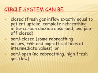


This document discusses the circle system used in anesthesia. It describes the components of the circle system including the absorber, canisters, unidirectional valves, fresh gas inlet, adjustable pressure limiting valve, and reservoir bag. It explains how the circle system works and how it can be configured as a closed, semi-closed, or semi-open system depending on the fresh gas flow. It also discusses the advantages and disadvantages of the circle system and components like the absorber, how it neutralizes carbon dioxide, and factors that influence compound A and carbon monoxide formation.


