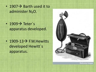
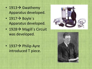
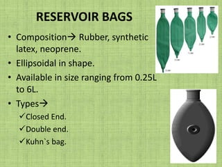
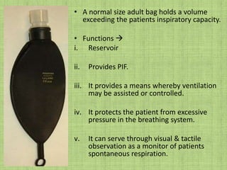
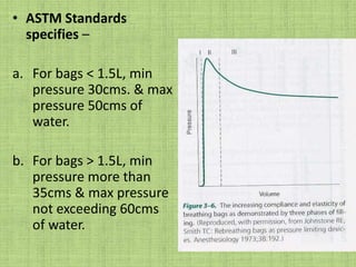
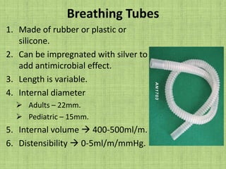
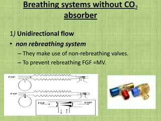
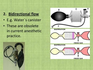
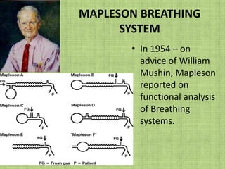
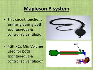
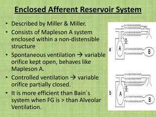
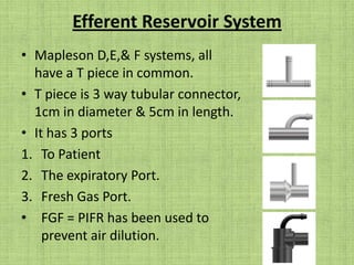
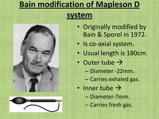
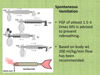
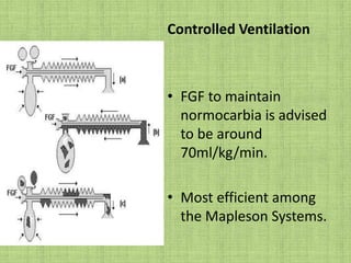
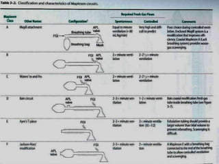
J.J.M MEDICAL COLLEGE, DAVANGEREDEPARTMENT OF ANESTHESIOLOGYSEMINAR ON BREATHING SYSTEMS                            OPEN CIRCUITCHAIR PERSON                            PRESENTED BYDR. PRIYADARSHINI M.B            DR. SHOEIBM.D           P.G IN ANESTHESIAASSISTANT PROFESSORDATE-- 01-06-2010.
“NECESSITY IS MOTHER OF INVENTION” Earlier circuits were simple, differing in the type of anesthetic agent administered.The purpose of breathing systems that have evolved in anesthetic practice is to deliver Gas & Vapor to the patient in an appropriate, controlled & efficient manner.
1846 Sir W.T.G Morton did public demonstration with      Ether.
1876  Clover`s Inhaler developed by J.T Clover.
1907 Barth used it to administer N₂O.1909 Teter`s apparatus developed.1909-13 F.W.Hewitts developed Hewitt`s apparatus.
1913 Gwathemy Apparatus developed.1917 Boyle`s Apparatus developed.1928 Magill`s Circuit was developed.1937 Philip Ayre introduced T piece.
1972 J.A Bain & W.E Spoerel introduced Bain`s Circuit.1975 Dr Gordon Jackson Rees developed Mapleson F system.Humphrey Davy, Brock & Downing  developed combined ADE system.
DefinitionA breathing system is defined as an assembly of components, which connects the patient’s airway to the anesthetic machine creating an artificial atmosphere form and into which the patient breathes.The breathing system converts a continuous flow from the anaesthesia machine to an intermittent flow;
In practice the breathing system is usually regarded as extending from the point of fresh gas inlet to the point at which gas escapes to the atmosphere or a scavenging system.Rebreathing: in anesthetic systems, it now conventionally refers to the breathing again of some or all of the previously exhaled gases including CO2 & water vapor.
Components of breathing system: Formally these were called breathing apparatus or breathing circuits. These names have been abandoned. It primarily consists ofA fresh gas entry port/delivery tube through which gases are delivered from the machine to the systems.A port to connect it to the patients airway.A reservoir for a gas in the form of a bag or a corrugated tube to meet the peak inspiratory flow requirements
d) An expiratory port/valve through which the expired gas is vented to the atmosphere.e) Corrugated tubes for connecting these components.f) Flow directing valves may or may not be used. g) A CO2 absorber if total rebreathing is to be allowed.
h) Connectors & adaptors  A connector is a fitting that joins together 2 or more similar components. An adaptor is a specialized connector that establishes functional continuity between otherwise disparate or incompatible components.There sizes are universal & either male/female, 15/22mm connections. Some incorporate gas sampling ports.
Bacterial filters- they prevent transmission of infection to the patients or contamination of equipments.Generally a new filter should be used for every patient or in the absence of filter, a disposable system should be used on every patient.
j) Heat & Moisture Exchange (HME Filters)-These humidify & warm the Anesthetic gases being delivered to the patients.These devices also help to dehumidify the gases that are been sampled for analysis by the side stream devices
RESERVOIR BAGSComposition Rubber, synthetic latex, neoprene.Ellipsoidal in shape.Available in size ranging from 0.25L to 6L.Types Closed End.
Double end.
Kuhn`s bag.A normal size adult bag holds a volume exceeding the patients inspiratory capacity.Functions ReservoirProvides PIF.It provides a means whereby ventilation may be assisted or controlled.It protects the patient from excessive pressure in the breathing system.It can serve through visual & tactile observation as a monitor of patients spontaneous respiration.
ASTM Standards specifies –For bags < 1.5L, min pressure 30cms. & max pressure 50cms of water.For bags > 1.5L, min pressure more than 35cms & max pressure not exceeding 60cms of water.
Breathing TubesMade of rubber or plastic or silicone.Can be impregnated with silver to add antimicrobial effect.Length is variable.Internal diameter Adults – 22mm.
Pediatric – 15mm.Internal volume  400-500ml/m.Distensibility 0-5ml/m/mmHg.
Resistance to gas flow  <1mm of H₂O/litre/min of flowCorrugations prevent kinking & increased flexibility.Backlash  seen during spontaneous breathing.Wasted ventilation  seen during controlled breathing.FunctionsAct as reservoir in certain systems.They provide connection from 1part of system to another.
Adjustable Pressure Limiting Valve (APL Valve)	Also called as expiratory valve, pressure relief valve, pop off valve, Heidbrink  valve, Dump valve, Exhaust valve, Spill valve etc
TYPES OF APL VALVESSpring Loaded DiscMost commonly used type.
Has 3 ports –Inlet, The Patient & Exhaust Port.Exhaust port may be open to atmosphere or scavenging system.Stem & Seat typeControl Knob typeCollection Device & Exhaust Port
Humphrey Type valve.                                       APL Valves with InbuiltOverpressure Safety devices
Uses of APL valves in spontaneous & controlled ventilation.SpontaneousValve is kept fully opened.
Partial closing will result in PEEP.
Pressure <1cm H₂O needed to open valve.
Should have pressure drop 1-3cm of H₂O for airflow of 3L/min & 1-5cms of water at 30L/min.ControlledValve is partially left open.Essential/ Principle CriteriaThe breathing system mustDeliver the gases from the machine to the alveoli in the same concentration as set and in the shortest possible time.b) Effectively eliminate carbon-dioxide.c) Have minimal apparatus dead space.d) Have low resistance.
Desirable/Secondary CriteriaThe desirable requirements areeconomy of fresh gas.b) conservation of heat.c) adequate humidification of inspired gas.d) light weight
e) Convenience during use.f) Efficiency during spontaneous as well as controlled ventilation (efficiency is determined in terms of CO2 elimination and fresh gas utilization)g) Adaptability for adults, children and mechanical ventilatorsh) Provision to reduce theatre pollution
Dripps classificationIt is based on rebreathing, presence or absence of reservoir, CO2 absorption & directional valves. Insufflation system – gases are delivered directly into the patient’s airways, no reservoir bag, no valves, no CO2 absorber – open drop methodOpen type – gases are directed to the patient from anesthesia machine, and valves direct exhaled gases to the atmosphere – intermittent flow machines, systems with non rebreathing valves
Semiopen type – mixing of inspired and expired gases occur and rebreathing depends on fresh gas flow. No CO2 absorber – Mapleson systemsSemiclosed system – part of the exhaled gases go out to the atmosphere, part of it gets mixed with inspired gases and is rebreathed. CO2 absorber is presentClosed system – complete rebreathing of expired gas. CO2 absorber is present.
Breathing systems without CO2 absorber1) Unidirectional flownon rebreathing systemThey make use of non-rebreathing valves.To prevent rebreathing FGF =MV.
Though it satisfies all the 4 essential requirements, still not very popular becauseFresh gas flow has to be constantly adjusted and is not economical.2) There is no humidification of inspired gases.3) There is no conservation of heat
4) The valve is bulky and has to be placed close to the patient.5) Malfunctioning of the valve can occur due to condensation of moisture.6) Can be noisy at times.7) Cleaning and sterilization is somewhat difficult
Bidirectional flowE.g. Water`s canisterThese are obsolete in current anesthetic practice.
MAPLESON BREATHING SYSTEMIn 1954 – on advice of William Mushin, Mapleson reported on functional analysis of Breathing systems.
For better understanding of functional analysis they have been classified asAfferent Reservoir System (ARS)2) Enclosed Afferent Reservoir System3) Efferent Reservoir System4) Combined SystemThe efficiency of a system is determined in terms of CO₂ elimination & FGF utilization.
Afferent limb is that part of the breathing system which delivers the fresh gas from the machine to the patient. If the reservoir is placed in this limb as in Mapleson A, B, C and Lack’s systems they are called as afferent reservoir system.Efferent limb is that part of the breathing system which carries the expired gas from the patient and vents it to the atmosphere through the expiratory valve/port. If the reservoir is placed in this limb as in Mapleson D, E, F and Bain systems they are called efferent reservoir system
For spontaneous ventilation in the order of efficiency – ADCB (All Dogs Can Bite).For controlled ventilation – DBCA (Dead Bodies Can’t Argue)Here D includes E, F and Bain`s system
Mapleson postulates (1954)Mapleson has analyzed these bi-directional flow systems & few basic assumptions have been made which are of historical interest. Gases move En-bloc i.e they maintain their identity as fresh gas, dead space gas & alveolar gas. There is no mixing of these gases.
Reservoir bags continues to fill up, without offering any resistance till it is full.The expiratory valve opens as soon as the reservoir bag is full & pressure inside the system goes above the atmospheric pressure.The valve remains open throughout the expiratory phase without offering any resistance to gas flow & closes at the start of next inspiration.
Mapleson A/Magill’s systemOriginally described by Evan Magill.Length of breathing tube  110-180 cms.FGF  from machine end.APL  close to patient.Sampling ports to be placed between APL valve & the tube.
Spontaneous Breathing3 phases identified InspiratoryExpiratoryExpiratory Pause.
FunctionTo prevent rebreathing FGF=MV is advised.FGF = 70 ml/kg/min is recommended.Extremely efficient system for spontaneous ventilation.
mapelsonA.swf
Controlled VentilationThese systems are inneficient for controlled ventilation.FGF >20L/min required for CO₂ elimination.This system cannot be used in patients less than 30kgs.
FunctionLack systemCo-axial Mapleson A.Outer tube 30mm in diameter.Inner tube 14mm in diameter.APL valve placed near patients end.
Testing for Leaks in Magills & Lacks Magill – tested for leaks by occluding the patient end & closing valve & pressurizing the system. Opening the APL valve will conform proper functioning of the component.In addition the user or patient should breathe through the system to rule out block.
Lack – tested same as for Mapleson A with testing integrity of inner tube. ET tube is attached to inner tube & valve is closed. Air is blown. If leak is present, excursions will be seen in the reservoir bag.Occlude both the limbs with APL valve open, squeeze the bag. Any leak is confirmed by release of gas from APL valve.
Mapleson B systemThis circuit functions similarly during both spontaneous & controlled ventilation.FGF > 2x Min Volume used for both spontaneous & controlled ventilation.
Mapleson C systemAlso called as Westminster face pieceFGF > 2 x Min Volume for both Spontaneous & controlled.Used for short periods during transportation of patient.
Enclosed Afferent Reservoir SystemDescribed by Miller & Miller.Consists of Mapleson A system enclosed within a non-distensible structureSpontaneous ventilation  variable orifice kept open, behaves like Mapleson A.Controlled ventilation  variable orifice partially closed.It is more efficient than Bain`s system when FG is > than Alveolar Ventilation.
Efferent Reservoir SystemMapleson D,E,& F systems, all have a T piece in common. T piece is 3 way tubular connector, 1cm in diameter & 5cm in length. It has 3 ports To PatientThe expiratory Port.Fresh Gas Port.FGF = PIFR has been used to prevent air dilution.
Bain modification of Mapleson D systemOriginally modified by Bain & Sporel in 1972.Is co-axial system.Usual length is 180cm.Outer tube  Diameter -22mm.Carries exhaled gas.Inner tube Diameter-7mm.Carries fresh gas.
Spontaneous VentilationFGF of atleast 1.5-3 times MV is advised to prevent rebreathing.Based on body wt. 200 ml/kg/min flow has been recommended.
Controlled VentilationFGF to maintain normocarbia is advised to be around 70ml/kg/min.Most efficient among the Mapleson Systems.
Recommendations by Bain & Sporel2L/min FGF in patients <10kg.3.5L/min FGF in patients between 10-50 kg.70ml/kg/min FGF in patients more than 60kg.Tidal volume to be set at 10ml/kg.Respiratory rate at 12-16 breaths/min.
Advantages of Bains circuit1) light weight2) convenient to use3) easily sterilized and reusable4) scavenging of exhaled gases is facilitated5) exhaled gases in the outer tubing add warmth tothe inspired gases6) a long corrugated tubing with an aluminium APL valve may be used to ventilate a patient undergoing MRI
Testing – For the integrity of the inner tubeSet a low flow of O2 on the flow meter and occluding the inner tube (with a finger or the barren of a small syringe) at the patient end while observing the flowmeter indicator. If the inner tube is intact and correctly connected, the indicator will fall.
2) Pethick’s test –High flow O2 is fed into the circuit while the patient end is occluded until the bag is filled.The patient end is opened and simultaneously ‘O2 flush’ is activated. If the inner tube is intact, the Venturi effect occurring at the patient end, causes a decrease in pressure within the circuit and the reservoir bag deflates. Conversely if there is a leak in the inner tube, gas escapes into the outer tube and the reservoir bag remains inflated
Mapleson E systemModification of Ayre`s T Piece.Used initially for pediatric patients undergoing palate repair & intracranial surgery.Minimal dead space, no valves, v.little resistance.Volume of expiratory limb > Pts tidal volume to prevent air dilution.
Used in children weighing 25-30kg.Sampling port is between expiratory port & tubing.FGF > 3 times min. volume
Problems with this system are Air dilution of the expiratory limb is short.2) High fresh gas flow is required to prevent rebreathing and air dilution.3) During controlled ventilation feel of the bag is not there and hence hazard of ‘barotrauma’ is a possibility.Used to administer O₂ for spontaneously breathing patients in ICU.
Mapleson F system(JACKSON-REES)T piece arrangement with a reservoir bag.Relief mechanism is either an adjustable valve at end of bag or a hole on side of Bag.Newer modification incorporates APL valve before the reservoir bag. Pressure relief is actuated at 30cms of water.FGF = 2-3 x MV for spontaneous respiration.FGF = Bain`s for controlled respiration.
1) light weight 2) simple construction3) inexpensive4) minimal resistance5) minimal dead space6) controlled ventilation is easily done7) scavenging is easily facilitated.
Hazards1) lack of humidification2) need for high fresh gas flows3) occlusion of relief valve can increase the airway pressure, producing barotraumas
Advantages of Mapleson systemsthe equipment is simple, inexpensive and rugged.2) components can be easily disassembled and can be sterilized.3) the systems provide buffering effect so that variations in minute volume affect end tidal CO2 less than in a circle system4) rebreathing will result in retention of heat and moisture5) resistance is within the recommended ranges
6) light weight and not bulky7) do not cause excessive drag on ET tube8) easy to position conveniently.9) compression & compliance losses are less with these systems than with circle systems.10) Changes in fresh gas concentration result in rapid changes in inspiratory gas composition
Disadvantagesrequire high gas flows, higher costs, increased atmospheric pollution.2) optimal fresh gas flow may be difficult to determine. Necessary to change fresh gas flows when changing from spontaneous to controlled mode.3) anything that causes decreased fresh gas flow can produce dangerous rebreathing

Breathing systems open circuit- shoeib

  • 1.
    J.J.M MEDICAL COLLEGE,DAVANGEREDEPARTMENT OF ANESTHESIOLOGYSEMINAR ON BREATHING SYSTEMS OPEN CIRCUITCHAIR PERSON PRESENTED BYDR. PRIYADARSHINI M.B DR. SHOEIBM.D P.G IN ANESTHESIAASSISTANT PROFESSORDATE-- 01-06-2010.
  • 2.
    “NECESSITY IS MOTHEROF INVENTION” Earlier circuits were simple, differing in the type of anesthetic agent administered.The purpose of breathing systems that have evolved in anesthetic practice is to deliver Gas & Vapor to the patient in an appropriate, controlled & efficient manner.
  • 3.
    1846 Sir W.T.GMorton did public demonstration with Ether.
  • 4.
    1876  Clover`sInhaler developed by J.T Clover.
  • 5.
    1907 Barth usedit to administer N₂O.1909 Teter`s apparatus developed.1909-13 F.W.Hewitts developed Hewitt`s apparatus.
  • 6.
    1913 Gwathemy Apparatusdeveloped.1917 Boyle`s Apparatus developed.1928 Magill`s Circuit was developed.1937 Philip Ayre introduced T piece.
  • 7.
    1972 J.A Bain& W.E Spoerel introduced Bain`s Circuit.1975 Dr Gordon Jackson Rees developed Mapleson F system.Humphrey Davy, Brock & Downing  developed combined ADE system.
  • 8.
    DefinitionA breathing systemis defined as an assembly of components, which connects the patient’s airway to the anesthetic machine creating an artificial atmosphere form and into which the patient breathes.The breathing system converts a continuous flow from the anaesthesia machine to an intermittent flow;
  • 9.
    In practice thebreathing system is usually regarded as extending from the point of fresh gas inlet to the point at which gas escapes to the atmosphere or a scavenging system.Rebreathing: in anesthetic systems, it now conventionally refers to the breathing again of some or all of the previously exhaled gases including CO2 & water vapor.
  • 10.
    Components of breathingsystem: Formally these were called breathing apparatus or breathing circuits. These names have been abandoned. It primarily consists ofA fresh gas entry port/delivery tube through which gases are delivered from the machine to the systems.A port to connect it to the patients airway.A reservoir for a gas in the form of a bag or a corrugated tube to meet the peak inspiratory flow requirements
  • 11.
    d) An expiratoryport/valve through which the expired gas is vented to the atmosphere.e) Corrugated tubes for connecting these components.f) Flow directing valves may or may not be used. g) A CO2 absorber if total rebreathing is to be allowed.
  • 12.
    h) Connectors &adaptors  A connector is a fitting that joins together 2 or more similar components. An adaptor is a specialized connector that establishes functional continuity between otherwise disparate or incompatible components.There sizes are universal & either male/female, 15/22mm connections. Some incorporate gas sampling ports.
  • 13.
    Bacterial filters- theyprevent transmission of infection to the patients or contamination of equipments.Generally a new filter should be used for every patient or in the absence of filter, a disposable system should be used on every patient.
  • 14.
    j) Heat &Moisture Exchange (HME Filters)-These humidify & warm the Anesthetic gases being delivered to the patients.These devices also help to dehumidify the gases that are been sampled for analysis by the side stream devices
  • 15.
    RESERVOIR BAGSComposition Rubber,synthetic latex, neoprene.Ellipsoidal in shape.Available in size ranging from 0.25L to 6L.Types Closed End.
  • 16.
  • 17.
    Kuhn`s bag.A normalsize adult bag holds a volume exceeding the patients inspiratory capacity.Functions ReservoirProvides PIF.It provides a means whereby ventilation may be assisted or controlled.It protects the patient from excessive pressure in the breathing system.It can serve through visual & tactile observation as a monitor of patients spontaneous respiration.
  • 18.
    ASTM Standards specifies–For bags < 1.5L, min pressure 30cms. & max pressure 50cms of water.For bags > 1.5L, min pressure more than 35cms & max pressure not exceeding 60cms of water.
  • 19.
    Breathing TubesMade ofrubber or plastic or silicone.Can be impregnated with silver to add antimicrobial effect.Length is variable.Internal diameter Adults – 22mm.
  • 20.
    Pediatric – 15mm.Internalvolume  400-500ml/m.Distensibility 0-5ml/m/mmHg.
  • 21.
    Resistance to gasflow  <1mm of H₂O/litre/min of flowCorrugations prevent kinking & increased flexibility.Backlash  seen during spontaneous breathing.Wasted ventilation  seen during controlled breathing.FunctionsAct as reservoir in certain systems.They provide connection from 1part of system to another.
  • 22.
    Adjustable Pressure LimitingValve (APL Valve) Also called as expiratory valve, pressure relief valve, pop off valve, Heidbrink valve, Dump valve, Exhaust valve, Spill valve etc
  • 23.
    TYPES OF APLVALVESSpring Loaded DiscMost commonly used type.
  • 24.
    Has 3 ports–Inlet, The Patient & Exhaust Port.Exhaust port may be open to atmosphere or scavenging system.Stem & Seat typeControl Knob typeCollection Device & Exhaust Port
  • 25.
    Humphrey Type valve. APL Valves with InbuiltOverpressure Safety devices
  • 26.
    Uses of APLvalves in spontaneous & controlled ventilation.SpontaneousValve is kept fully opened.
  • 27.
    Partial closing willresult in PEEP.
  • 28.
    Pressure <1cm H₂Oneeded to open valve.
  • 29.
    Should have pressuredrop 1-3cm of H₂O for airflow of 3L/min & 1-5cms of water at 30L/min.ControlledValve is partially left open.Essential/ Principle CriteriaThe breathing system mustDeliver the gases from the machine to the alveoli in the same concentration as set and in the shortest possible time.b) Effectively eliminate carbon-dioxide.c) Have minimal apparatus dead space.d) Have low resistance.
  • 30.
    Desirable/Secondary CriteriaThe desirablerequirements areeconomy of fresh gas.b) conservation of heat.c) adequate humidification of inspired gas.d) light weight
  • 31.
    e) Convenience duringuse.f) Efficiency during spontaneous as well as controlled ventilation (efficiency is determined in terms of CO2 elimination and fresh gas utilization)g) Adaptability for adults, children and mechanical ventilatorsh) Provision to reduce theatre pollution
  • 32.
    Dripps classificationIt isbased on rebreathing, presence or absence of reservoir, CO2 absorption & directional valves. Insufflation system – gases are delivered directly into the patient’s airways, no reservoir bag, no valves, no CO2 absorber – open drop methodOpen type – gases are directed to the patient from anesthesia machine, and valves direct exhaled gases to the atmosphere – intermittent flow machines, systems with non rebreathing valves
  • 33.
    Semiopen type –mixing of inspired and expired gases occur and rebreathing depends on fresh gas flow. No CO2 absorber – Mapleson systemsSemiclosed system – part of the exhaled gases go out to the atmosphere, part of it gets mixed with inspired gases and is rebreathed. CO2 absorber is presentClosed system – complete rebreathing of expired gas. CO2 absorber is present.
  • 35.
    Breathing systems withoutCO2 absorber1) Unidirectional flownon rebreathing systemThey make use of non-rebreathing valves.To prevent rebreathing FGF =MV.
  • 36.
    Though it satisfiesall the 4 essential requirements, still not very popular becauseFresh gas flow has to be constantly adjusted and is not economical.2) There is no humidification of inspired gases.3) There is no conservation of heat
  • 37.
    4) The valveis bulky and has to be placed close to the patient.5) Malfunctioning of the valve can occur due to condensation of moisture.6) Can be noisy at times.7) Cleaning and sterilization is somewhat difficult
  • 38.
    Bidirectional flowE.g. Water`scanisterThese are obsolete in current anesthetic practice.
  • 39.
    MAPLESON BREATHING SYSTEMIn1954 – on advice of William Mushin, Mapleson reported on functional analysis of Breathing systems.
  • 40.
    For better understandingof functional analysis they have been classified asAfferent Reservoir System (ARS)2) Enclosed Afferent Reservoir System3) Efferent Reservoir System4) Combined SystemThe efficiency of a system is determined in terms of CO₂ elimination & FGF utilization.
  • 41.
    Afferent limb isthat part of the breathing system which delivers the fresh gas from the machine to the patient. If the reservoir is placed in this limb as in Mapleson A, B, C and Lack’s systems they are called as afferent reservoir system.Efferent limb is that part of the breathing system which carries the expired gas from the patient and vents it to the atmosphere through the expiratory valve/port. If the reservoir is placed in this limb as in Mapleson D, E, F and Bain systems they are called efferent reservoir system
  • 42.
    For spontaneous ventilationin the order of efficiency – ADCB (All Dogs Can Bite).For controlled ventilation – DBCA (Dead Bodies Can’t Argue)Here D includes E, F and Bain`s system
  • 43.
    Mapleson postulates (1954)Maplesonhas analyzed these bi-directional flow systems & few basic assumptions have been made which are of historical interest. Gases move En-bloc i.e they maintain their identity as fresh gas, dead space gas & alveolar gas. There is no mixing of these gases.
  • 44.
    Reservoir bags continuesto fill up, without offering any resistance till it is full.The expiratory valve opens as soon as the reservoir bag is full & pressure inside the system goes above the atmospheric pressure.The valve remains open throughout the expiratory phase without offering any resistance to gas flow & closes at the start of next inspiration.
  • 45.
    Mapleson A/Magill’s systemOriginallydescribed by Evan Magill.Length of breathing tube  110-180 cms.FGF  from machine end.APL  close to patient.Sampling ports to be placed between APL valve & the tube.
  • 46.
    Spontaneous Breathing3 phasesidentified InspiratoryExpiratoryExpiratory Pause.
  • 47.
    FunctionTo prevent rebreathingFGF=MV is advised.FGF = 70 ml/kg/min is recommended.Extremely efficient system for spontaneous ventilation.
  • 48.
  • 49.
    Controlled VentilationThese systemsare inneficient for controlled ventilation.FGF >20L/min required for CO₂ elimination.This system cannot be used in patients less than 30kgs.
  • 50.
    FunctionLack systemCo-axial MaplesonA.Outer tube 30mm in diameter.Inner tube 14mm in diameter.APL valve placed near patients end.
  • 51.
    Testing for Leaksin Magills & Lacks Magill – tested for leaks by occluding the patient end & closing valve & pressurizing the system. Opening the APL valve will conform proper functioning of the component.In addition the user or patient should breathe through the system to rule out block.
  • 52.
    Lack – testedsame as for Mapleson A with testing integrity of inner tube. ET tube is attached to inner tube & valve is closed. Air is blown. If leak is present, excursions will be seen in the reservoir bag.Occlude both the limbs with APL valve open, squeeze the bag. Any leak is confirmed by release of gas from APL valve.
  • 53.
    Mapleson B systemThiscircuit functions similarly during both spontaneous & controlled ventilation.FGF > 2x Min Volume used for both spontaneous & controlled ventilation.
  • 54.
    Mapleson C systemAlsocalled as Westminster face pieceFGF > 2 x Min Volume for both Spontaneous & controlled.Used for short periods during transportation of patient.
  • 55.
    Enclosed Afferent ReservoirSystemDescribed by Miller & Miller.Consists of Mapleson A system enclosed within a non-distensible structureSpontaneous ventilation  variable orifice kept open, behaves like Mapleson A.Controlled ventilation  variable orifice partially closed.It is more efficient than Bain`s system when FG is > than Alveolar Ventilation.
  • 56.
    Efferent Reservoir SystemMaplesonD,E,& F systems, all have a T piece in common. T piece is 3 way tubular connector, 1cm in diameter & 5cm in length. It has 3 ports To PatientThe expiratory Port.Fresh Gas Port.FGF = PIFR has been used to prevent air dilution.
  • 57.
    Bain modification ofMapleson D systemOriginally modified by Bain & Sporel in 1972.Is co-axial system.Usual length is 180cm.Outer tube  Diameter -22mm.Carries exhaled gas.Inner tube Diameter-7mm.Carries fresh gas.
  • 58.
    Spontaneous VentilationFGF ofatleast 1.5-3 times MV is advised to prevent rebreathing.Based on body wt. 200 ml/kg/min flow has been recommended.
  • 59.
    Controlled VentilationFGF tomaintain normocarbia is advised to be around 70ml/kg/min.Most efficient among the Mapleson Systems.
  • 60.
    Recommendations by Bain& Sporel2L/min FGF in patients <10kg.3.5L/min FGF in patients between 10-50 kg.70ml/kg/min FGF in patients more than 60kg.Tidal volume to be set at 10ml/kg.Respiratory rate at 12-16 breaths/min.
  • 61.
    Advantages of Bainscircuit1) light weight2) convenient to use3) easily sterilized and reusable4) scavenging of exhaled gases is facilitated5) exhaled gases in the outer tubing add warmth tothe inspired gases6) a long corrugated tubing with an aluminium APL valve may be used to ventilate a patient undergoing MRI
  • 62.
    Testing – Forthe integrity of the inner tubeSet a low flow of O2 on the flow meter and occluding the inner tube (with a finger or the barren of a small syringe) at the patient end while observing the flowmeter indicator. If the inner tube is intact and correctly connected, the indicator will fall.
  • 63.
    2) Pethick’s test–High flow O2 is fed into the circuit while the patient end is occluded until the bag is filled.The patient end is opened and simultaneously ‘O2 flush’ is activated. If the inner tube is intact, the Venturi effect occurring at the patient end, causes a decrease in pressure within the circuit and the reservoir bag deflates. Conversely if there is a leak in the inner tube, gas escapes into the outer tube and the reservoir bag remains inflated
  • 64.
    Mapleson E systemModificationof Ayre`s T Piece.Used initially for pediatric patients undergoing palate repair & intracranial surgery.Minimal dead space, no valves, v.little resistance.Volume of expiratory limb > Pts tidal volume to prevent air dilution.
  • 65.
    Used in childrenweighing 25-30kg.Sampling port is between expiratory port & tubing.FGF > 3 times min. volume
  • 66.
    Problems with thissystem are Air dilution of the expiratory limb is short.2) High fresh gas flow is required to prevent rebreathing and air dilution.3) During controlled ventilation feel of the bag is not there and hence hazard of ‘barotrauma’ is a possibility.Used to administer O₂ for spontaneously breathing patients in ICU.
  • 67.
    Mapleson F system(JACKSON-REES)Tpiece arrangement with a reservoir bag.Relief mechanism is either an adjustable valve at end of bag or a hole on side of Bag.Newer modification incorporates APL valve before the reservoir bag. Pressure relief is actuated at 30cms of water.FGF = 2-3 x MV for spontaneous respiration.FGF = Bain`s for controlled respiration.
  • 68.
    1) light weight2) simple construction3) inexpensive4) minimal resistance5) minimal dead space6) controlled ventilation is easily done7) scavenging is easily facilitated.
  • 69.
    Hazards1) lack ofhumidification2) need for high fresh gas flows3) occlusion of relief valve can increase the airway pressure, producing barotraumas
  • 71.
    Advantages of Maplesonsystemsthe equipment is simple, inexpensive and rugged.2) components can be easily disassembled and can be sterilized.3) the systems provide buffering effect so that variations in minute volume affect end tidal CO2 less than in a circle system4) rebreathing will result in retention of heat and moisture5) resistance is within the recommended ranges
  • 72.
    6) light weightand not bulky7) do not cause excessive drag on ET tube8) easy to position conveniently.9) compression & compliance losses are less with these systems than with circle systems.10) Changes in fresh gas concentration result in rapid changes in inspiratory gas composition
  • 73.
    Disadvantagesrequire high gasflows, higher costs, increased atmospheric pollution.2) optimal fresh gas flow may be difficult to determine. Necessary to change fresh gas flows when changing from spontaneous to controlled mode.3) anything that causes decreased fresh gas flow can produce dangerous rebreathing