Downloaded 141 times
![IJRET: International Journal of Research in Engineering and Technology eISSN: 2319-1163 | pISSN: 2321-7308
_______________________________________________________________________________________
Volume: 03 Issue: 05 | May-2014, Available @ http://www.ijret.org 50
MAGLEV WINDMILL
Minu John1
, Rohit John2
, Syamily P.S3
, Vyshak P.A4
1
Student, Dept. of EEE, Mar Athanasius College of Engineering, Kothamangalam, India
2
Student, Dept. of EEE, Mar Athanasius College of Engineering, Kothamangalam, India
3
Student, Dept. of EEE, Mar Athanasius College of Engineering, Kothamangalam, India
4
Student, Dept. of EEE, Mar Athanasius College of Engineering, Kothamangalam, India
Abstract
Magnetic levitation, maglev, or magnetic suspension is a method by which an object is suspended with no support other than magnetic
fields. Magnetic pressure is used to counteract the effects of the gravitational and any other accelerations. The principal advantage of
a maglev windmill from a conventional one is, as the rotor is floating in the air due to levitation, mechanical friction is totally elimi-
nated. That makes the rotation possible in very low wind speeds. Maglev wind turbines have several advantages over conventional
wind turbines. For instance, they’re able to use winds with starting speeds as low as 1.5 meters per second (m/s). Also, they could
operate in winds exceeding 40 m/s.
Keywords: Wind Energy, Magnetic Levitation, Power Generation, Magnets
-----------------------------------------------------------------------***-----------------------------------------------------------------------
1. INTRODUCTION
Wind is a form of solar energy. It is a natural power source that
can be economically used to generate electricity. The way in
which wind is created is from the atmosphere of the sun causing
areas of uneven heating. In conjunction with the uneven heating
of the sun, rotation of the earth and the rockiness of the earth’s
surface winds are formed. The terms wind energy or wind power
describes the process by which the wind is used to generate me-
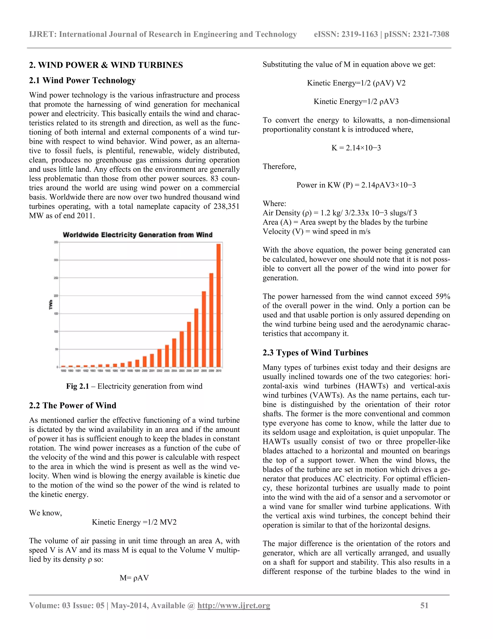
chanical power or electricity. Wind turbines convert the kinetic
energy in the wind into mechanical power. This mechanical
power can be used for specific tasks (such as grinding grain or
pumping water) or a generator can convert this mechanical pow-
er into electricity. The wind turbine is used for conversion of
kinetic energy of wind into electrical energy. The wind turns the
blades, which spin a shaft, which connects to a generator and
makes electricity.
The Maglev wind turbine design is a vast departure from con-
ventional propeller designs. Its main advantages are that it uses
frictionless bearings and a magnetic levitation design and it does
not need to vast spaces required by more conventional wind tur-
bines. It also requires little if any maintenance. The Maglev wind
turbine was first unveiled at the Wind Power Asia exhibition in
Beijing 2007. The unique operating principle behind this design
is through magnetic levitation. Magnetic levitation is supposedly
an extremely efficient system for wind energy. The vertically
oriented blades of the wind turbine are suspended in the air re-
placing any need for ball bearings.
1.1 Need for Wind Power Technology
Renewable energy is generally electricity supplied from
sources, such as wind power, solar power, geothermal
energy, hydropower and various forms of biomass. These
sources have been coined renewable due to their conti-
nuous replenishment and availability for use over and
over again. The popularity of renewable energy has expe-
rienced a significant upsurge in recent times due to the
exhaustion of conventional power generation methods
and increasing realization of its adverse effects on the
environment. It is estimated that renewable sources might
contribute about 20%-50% to energy consumption in the
later part of the 21st century. Facts from the World Wind
Energy Association estimates that by 2010, 160GW of
wind power capacity is expected to be installed world-
wide which implies an anticipated net growth rate of
more than 21% per year. Maglev wind turbines have sev-
eral advantages over conventional wind turbines. For
instance, they’re able to use winds with starting speeds as
low as 1.5 meters per second (m/s). Also, they could op-
erate in winds exceeding 40 m/s. It would also increase
generation capacity by 20% over conventional wind tur-
bines and decrease operational costs by 50%. This makes
the efficiency of the system higher than conventional
wind turbine. Currently, the largest conventional wind
turbines in the world produce only five megawatts of
power. However, one large maglev wind turbine could
generate one GW of clean power, enough to supply ener-
gy to 75,000 homes [1]
. The turbine uses permanent type
of rare earth magnets (neodymium) instead of electro-
magnets and therefore it doesn’t require electricity to run.
The friction between the turbine blades and the base can
maximum power output.](https://image.slidesharecdn.com/maglevwindmill-140813054609-phpapp01/75/Maglev-windmill-1-2048.jpg)
![IJRET: International Journal of Research in Engineering and Technology eISSN: 2319-1163 | pISSN: 2321-7308
_______________________________________________________________________________________
Volume: 03 Issue: 05 | May-2014, Available @ http://www.ijret.org 53
nets and magnetic fields are the dominant factors in this form of
generator functioning. These generators have air gap surface
perpendicular to the rotating axis and the air gap generates mag-
netic fluxes parallel to the axis. In further chapters we will take a
detailed look into their basic operation and the configuration of
our design.
3.3 Magnetic Levitation
Also known as maglev, this phenomenon operates on the repul-
sion characteristics of permanent magnets. This technology has
been predominantly utilized in the rail industry in the Far East to
provide very fast and reliable transportation on maglev trains and
with on-going research its popularity is increasingly attaining
new heights. Using a pair of permanent magnets like neodymium
magnets and substantial support magnetic levitation can easily be
experienced. By placing these two magnets on top of each other
with like polarities facing each other, the magnetic repulsion will
be strong enough to keep both magnets at a distance away from
each other. The force created as a result of this repulsion can be
used for suspension purposes and is strong enough to balance the
weight of an object depending on the threshold of the magnets.
In this project, we expect to implement this technology form the
purpose of achieving vertical orientation with our rotors as well
as the axial flux generator.
3.4 Power Generation
When designing a generator it is important to have a firm grasp
of the basic laws that govern its performance. In order to induce
a voltage in a wire a nearby changing magnetic field must exist.
The voltage induced not only depends on the magnitude of the
field density but also on the coil area. The relationship between
the area and field density is known as flux (Φ). The way in
which this flux varies in time depends on the generator design.
The axial flux generator uses the changing magnetic flux to pro-
duce a voltage. The voltage produced by each coil can be calcu-
lated using Faraday's law of induction,
V= -N(dO/dt)
3.4.1 Induced EMF
In order to explain how an axial flux generator is designed the
elements that produce an electromotive force or voltage must be
described. An induced EMF is produced by a time varying mag-
netic field. Michael Faraday performed experiments with steady
currents and a simple transformer in hopes of producing a vol-
tage from a magnetic field. He discovered that a constant mag-
netic field would not induce a voltage but a time varying field
could. This was an important discovery in what is known as elec-
tromagnetic induction, a discovery that is fundamental in the
design of a generator. It is this relative motion of a magnetic
field producing a voltage that allows us to be creative in the
ways we produce electricity.
3.4.2 Magnetic Flux
The magnitude of the magnetic flux is greatest when the
coil in a magnetic field is perpendicular to the field. In the
design of an axial flux generator it is best to keep the
coils perpendicular to the field produced by the perma-
nent magnets. In many conventional motors a winding
rotates inside a magnetic field. The number of windings is
increased so that each winding is positioned close to 90
degrees to the field. Figure 4.1 illustrates this concept. In
our design the angle between the coils and the field does
not change, instead the field itself varies with time.
Faraday's law of induction states that the induced elec-
tromotive force is equal to the change in magnetic flux
over the change in time.
V = −d∅/dt
4. MAGNETIC LEVITATION
In selecting the vertical axis concept for the wind turbine
that is implemented as the power generation portion of
this project, certain uniqueness corresponded to it that did
not pertain to the other wind turbine designs. The charac-
teristic that set this wind generator apart from the others
is that it is fully supported and rotates about a vertical
axis. This axis is vertically oriented through the center of
the wind sails, which allows for a different type of rota-
tional support rather than the conventional ball bearing
system found in horizontal wind turbines.
This support is called maglev, which is based on magnet-
ic levitation. Maglev offers a near frictionless substitute
for ball bearings with little to no maintenance. The four
different classes are Alnico, Ceramic, Samarium Cobalt
and Neodymium Iron Boron also known Nd- Fe-B. Nd-
Fe-B is the most recent addition to this commercial list of
materials and at room temperature exhibits the highest
properties of all of the magnetic materials. It can be seen
in the B-H graph shown in Figure 5.1 that Nd-Fe-B has a
very attractive magnetic characteristic, which offers high
flux density operation and the ability to resist demagneti-
zation.
This attribute will be very important because the load that
will be levitated will be heavy and rotating high speeds,
which will exhibit a large downward force on the axis[3]
.
The next factor that needs to be considered is the shape
and size of the magnet which is directly related to the
placement of the magnets. It seems that levitation would
be most effective directly on the central axis line where,
under an evenly distributed load, the wind turbine center
of mass will be found as seen in Figure 5.2. This figure
shows a basic rendition of how the maglev will be inte-
grated into the design.](https://image.slidesharecdn.com/maglevwindmill-140813054609-phpapp01/75/Maglev-windmill-4-2048.jpg)
![IJRET: International Journal of Research in Engineering and Technology eISSN: 2319-1163 | pISSN: 2321-7308
_______________________________________________________________________________________
Volume: 03 Issue: 05 | May-2014, Available @ http://www.ijret.org 55
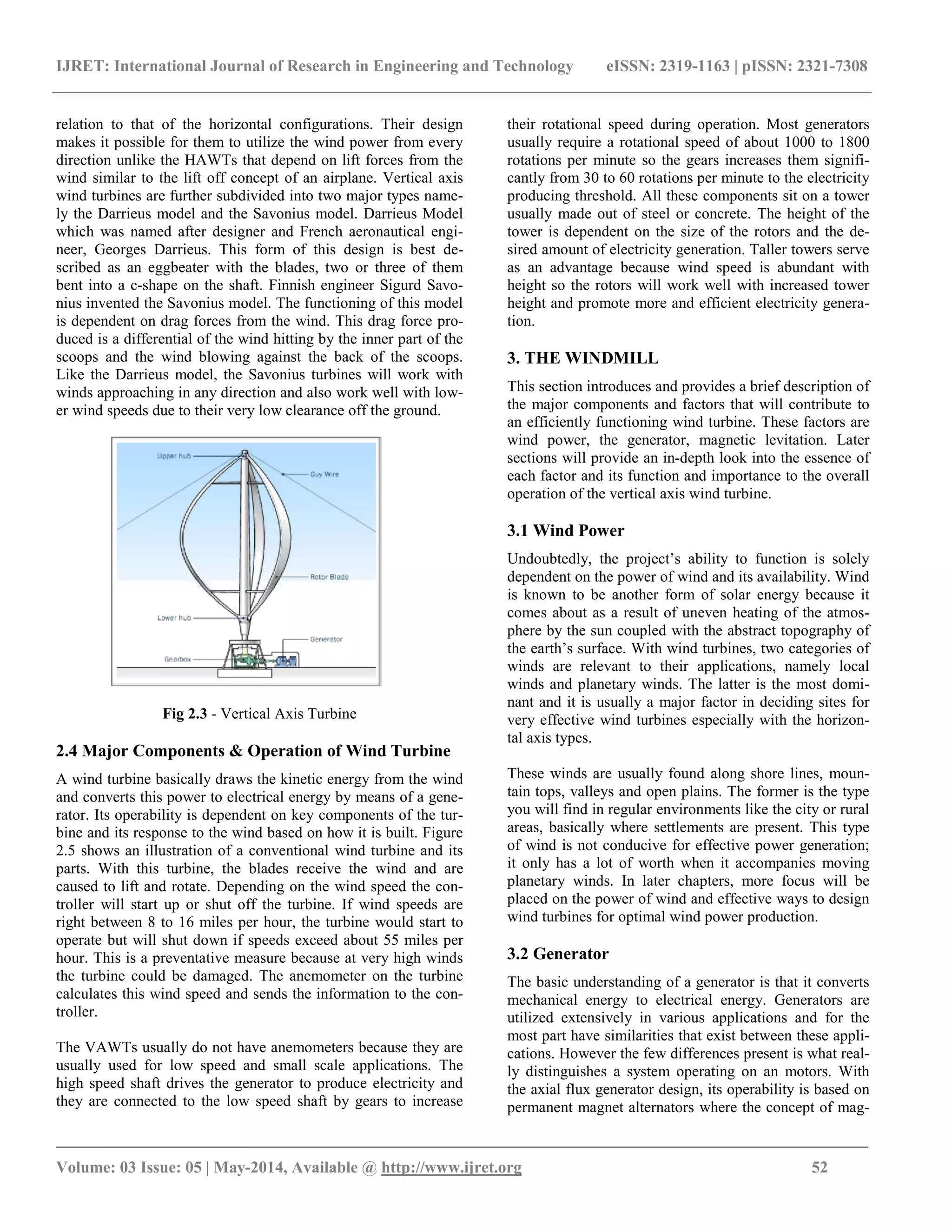
The coils are raised to a certain height for maximum utilization
of the magnetic flux. Each set of such coils are connected in se-
ries aiding to obtain maximum output voltage[4]
. The series con-
nections of the coils are preferred over the parallel connection
for optimizing a level between the output current and voltage.
The coil arrangement is shown in figure 6.2.
5.3 Levitation between Stator & Rotor
In the designed prototype, the stator and rotor are separated in
the air using the principle of magnetic levitation. The rotor is
lifted by a certain centimeters in the air by the magnetic pull
forces created by the ring type Neodymium magnets. This is the
principal advantage of a maglev windmill from a conventional
one. That is, as the rotor is floating in the air due to levitation,
mechanical friction is totally eliminated. That makes the rotation
possible in very low wind speeds. Figure 6.3 illustrates the mag-
netic levitation in our prototype.
Fig 6.3 - Magnetic Levitation
5.4 Blade Design
The blades used in this prototype are not of the conventional
type. In this prototype, As compared to the standard design mod-
el of the Savonius, we took a bit of a different approach in our
design by modifying it with a curvature design from the top of
the sails to the bottom[2]
. This design was attained with four tri-
angular shapes cut out from aluminum sheet metal and due to the
flexibility of the sheet metal, we were able to spiral the sail from
the top of the shaft to the base[6]
. The height of the blades were
400mm.
5.5 Final Model
The overall structure of the prototype designed is shown in the
figure 6.6. The output voltage obtained from this prototype is
measured using a multimeter and a maximum of 45 volts DC
were obtained.
A Led load of 3W is connected to the turbine and current is
measured to be 0.4 Amps.
6. CONCLUSIONS
At the end of the project, the magnetically levitated ver-
tical axis wind turbine was a success. The rotors that were
designed harnessed enough air to rotate at low and high
wind speeds while keeping the centre of mass closer to
the base yielding stability. The wind turbine rotor levi-
tated properly using permanent magnets, which allowed
for a smooth rotation with negligible friction.
Generator satisfied the specifications needed to supply
the LED load. An output ranging from 40V to 45V was
obtained from the magnetic levitated vertical axis wind
turbine prototype. A modified design of savonius model
wind turbine blade was used in the construction of the
model. An aluminium shaft was used to avoid the wob-
bling movement of the rotor. Overall, the magnetic levita-
tion wind turbine was a successful model.
Fig. 6.6 - Output waveform before & after rectification.
6.1 Limitations
In terms of large scale power production, vertical axis
wind turbines have not been known to be suitable for
these applications. Due to the overall structure and com-
plexity of the of the vertical axis wind turbine, to scale it
up to a size where it could provide the amount of power
to satisfy a commercial park or feed into the grid would
not be practical. The size of the rotors would have to be
immense and would cost too much to make. Aside from
the cost, this type of consumer would not desire the area
that it would consume and the aesthetics of the product.
Horizontal axis wind turbines are good for these applica-
tions because they do not take up as much space and are
positioned high up where they can obtain higher wind
speeds to provide an optimum power output.
6.2 Future Scope
The home for the magnetically levitated vertical axis
wind turbine would be in residential areas. Here it can be
mounted to a roof and be very efficient and practical. A
home owner would be able to extract free clean energy
thus experiencing a reduction in their utility cost and also
contribute to the “Green Energy” awareness that is in-
creasingly gaining popularity. The maglev windmill can](https://image.slidesharecdn.com/maglevwindmill-140813054609-phpapp01/75/Maglev-windmill-6-2048.jpg)
![IJRET: International Journal of Research in Engineering and Technology eISSN: 2319-1163 | pISSN: 2321-7308
_______________________________________________________________________________________
Volume: 03 Issue: 05 | May-2014, Available @ http://www.ijret.org 56
be designed for using in a moderate scale power generation rang-
ing from 400 Watts to 1 KW. Also it is suitable for integrating
with the hybrid power generation units consisting of solar and
other natural resources.
Fig 7.1 - The finished model generating a voltage of 40V.
ACKNOWLEDGEMENTS
I thank almighty for bestowing upon us all his blessings for the
compilation of this project. I would like to express our gratitude
to Dr. George Isaac, Principal, Mar Athanasius College of Engi-
neering, Kothamangalam and Prof. K. Radhakrishnan, Head of
the Department, Electrical and Electronics, for providing us with
the guidance and facilities for the project. A deep sense of grati-
tude to project guide Prof. Rajan P Thomas, whose overall direc-
tion and guidance has been responsible for the successful com-
pletion of this project. I express our sincere gratitude to Project
coordinator Prof. Elizabeth Sebastian, for her cooperation and
guidance for preparing Project. I also extend our sincere thanks
to all other faculty members of Electrical and Electronics De-
partment and our friends for their support and encouragement.
REFERENCES
[1] Dinesh N Nagarkarand Dr. Z. J. Khan,”Wind Power Plant
Using Magnetic Levitation Wind Turbine”, International-
Journal of Engineering and Innovative Technology
(IJEIT) Volume 3, Issue1, July 2013.
[2] Liu Shuqin,”Magnetic Suspension and Self-pitch for Ver-
tical-axis Wind Turbines”,
ISBN:http://www.intechopen.com/books/fundamental-
and-advanced-topics-in-wind-power/magnetic-
suspensionand-self-pitch-for-vertical-axis-wind-
turbines.2011.
[3] MagLev Wind Turbine Technologies, Inc.
(MWTT) & Off Grid Technologies, Inc. (OGT),”
Vertical Axis Wind Turbine 200 Mega Watt off
Shore Wind Farm (VAWT Off Shore JV)-City of
Evanston, Illinois Lake Michigan Project”.
[4] M. A. Mueller and A. S. McDonald,”A
lightweight low speed permanent magnet electrical
generator for direct-drive wind turbines”, Institute
for Energy Systems, Institute for Energy Systems,
Edinburgh University, Edinburgh University,
Edinburgh, UK.
[5] Vishal D Dhareppgoaland MaheshwariM Kona-
gutti,” REGENEDYNE Maglev Wind Power Gen-
eration”, SARC-IRAJ International Conference,
16th June 2013, Pune, India, ISBN: 978-81-
92747-8-3.](https://image.slidesharecdn.com/maglevwindmill-140813054609-phpapp01/75/Maglev-windmill-7-2048.jpg)

This document describes a proposed maglev windmill design. Some key points: - The maglev windmill uses magnetic levitation to suspend the turbine blades in air, eliminating mechanical friction and allowing the turbine to operate in very low wind speeds starting at 1.5 m/s. - The design aims to increase power generation capacity by 20% over conventional wind turbines and decrease operational costs by 50% by using magnetic levitation bearings. - The document provides background on wind power technologies, components of conventional wind turbines, and introduces the concept of using an axial flux generator and magnetic levitation in the proposed maglev windmill design.