Downloaded 1,088 times

![Muppandal, supplying the villagers with electricity for work. The village had been
selected as the showcase for India's $2 billion clean energy program which provides
foreign companies with tax breaks for establishing fields of wind turbines in the area.
In february 2009, Shriram EPC bagged INR 700 million contract for setting up of 60
units of 250 KW (totaling 15 MW) wind turbines in Tirunelveli district by Cape
Energy.[15] Enercon is also playing a major role in development of wind energy in
India. In Tamil Nadu, Coimbatore and Tiruppur Districts having more wind Mills from
2002 onwards,specially, Chittipalayam, Kethanoor, Gudimangalam,
Poolavadi,Murungappatti (MGV
Place),Sunkaramudaku,KongalNagaram,Gomangalam, Anthiur are the high wind
power production places in the both districts.
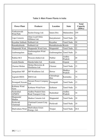
Maharashtra (2077.70 MW)
Maharashtra is second only to Tamil Nadu in terms of generating capacity. Suzlon
has been heavily involved. Suzlon operates what was once Asia's largest wind farm,
the Vankusawade Wind Park (201 MW), near the Koyna reservoir in Satara district of
Maharashtra.
Gujarat (1863.64 MW)
Samana & Sadodar in Jamanagar district is set to host energy companies like China
Light Power (CLP) and Tata Power have pledged to invest up to 8.15 billion ($189.5
million) in different projects in the area. CLP, through its India subsidiary CLP India,
is investing close to 5 billion for installing 126 wind turbines in Samana that will
generate 100.8 MW power. Tata Power has installed wind turbines in the same area
for generating 50 MW power at a cost of 3.15 billion. Both projects are expected to
become operational by early next year, according to government sources. The
Gujarat government, which is banking heavily on wind power, has identified Samana
as an ideal location for installation of 450 turbines that can generate a total of 360
MW. To encourage investment in wind energy development in the state, the
government has introduced a raft of incentives including a higher wind energy tariff.
Samana has a high tension transmission grid and electricity generated by wind
turbines can be fed into it. For this purpose, a substation at Sadodar has been
15 | P a g e](https://image.slidesharecdn.com/fyp-verticalaxis-turbine-140830205342-phpapp02/85/VERTICAL-AXIS-WIND-TURBINE-15-320.jpg)
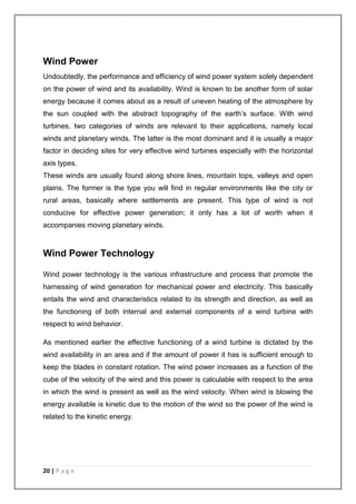
![Rajasthan (1088.37 MW)
Gurgaon-headquartered Gujarat Fluorochemicals Ltd is in an advanced stage of
commissioning a large wind farm in Jodhpur district of Rajasthan. A senior official
told Projectmonitor that out of the total 31.5 mw capacity, 12 mw had been
completed so far. The remaining capacity would come on line shortly, he added. For
the INOX Group company, this would be the largest wind farm. In 2006-07, GFL
commissioned a 23.1-mw wind power project at Gudhe village near Panchgani in
Satara district of Maharashtra. Both the wind farms will be grid-connected and will
earn carbon credits for the company, the official noted. In an independent
development, cement major ACC Ltd has proposed to set up a new wind power
project in Rajasthan with a capacity of around 11 mw. Expected to cost around 60
crore, the wind farm will meet the power requirements of the company's Lakheri
cement unit where capacity was raised from 0.9 million tpa to 1.5 million tpa through
a modernisation plan. For ACC, this would be the second wind power project after
the 9-mw farm at Udayathoor in Tirunelvelli district of Tamil Nadu.[citation needed]
Rajasthan is emerging as an important destination for new wind farms, although it is
currently not amongst the top five states in terms of installed capacity. As of 2007
end, this northern state had a total of 496 mw, accounting for a 6.3 per cent share in
India's total capacity.
Madhya Pradesh (229.39 MW)
In consideration of unique concept, Govt. of Madhya Pradesh has sanctioned
another 15 MW project to MPWL at Nagda Hills near Dewas. All the 25 WEGs have
been commissioned on 31.03.2008 and under successful operation.
Kerala (27.75 MW)
The first wind farm of the state was set up at Kanjikode in Palakkad district. It has a
generating capacity of 23.00 MW. A new wind farm project was launched with private
participation at Ramakkalmedu in Idukki district. The project, which was inaugurated
by chief minister V. S. Achuthanandan in April 2008, aims at generating 10.5 MW of
electricity.
The Agency for Non-Conventional Energy and Rural Technology (ANERT), an
autonomous body under the Department of Power, Government of Kerala, is setting
17 | P a g e](https://image.slidesharecdn.com/fyp-verticalaxis-turbine-140830205342-phpapp02/85/VERTICAL-AXIS-WIND-TURBINE-17-320.jpg)


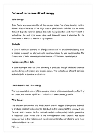
The document provides an overview of global energy consumption trends, highlighting a significant increase in energy demand in G20 countries and the continued reliance on renewable energy sources like wind, solar, and hydropower. It discusses the historical context of energy usage, the rise of wind power, and the potential for renewable energy to contribute significantly to future energy needs. It emphasizes the urgent necessity for energy security and the importance of diversifying energy sources amid rising fossil fuel costs and environmental concerns.