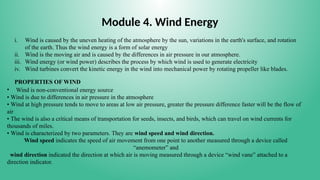
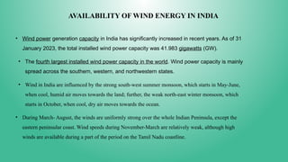
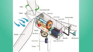
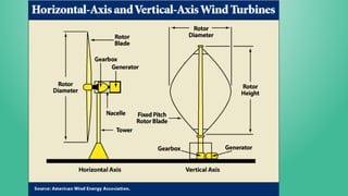
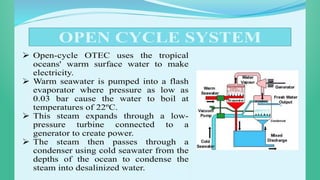
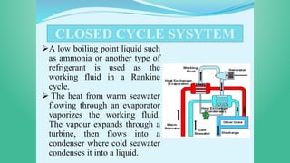
The document discusses wind energy, its causes, and how it's harnessed through wind turbines, which convert kinetic energy from wind into electricity. It highlights India's growing wind power capacity, challenges associated with wind energy, and the impact on wildlife and the environment. Additionally, it covers various types of wind turbines, their advantages, disadvantages, and design principles, along with a brief mention of tidal and ocean thermal energy.
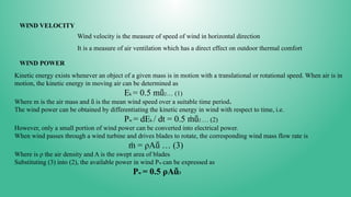
![AERODYNAMIC CONSIDERATIONS IN WIND MILL DESIGN
There are two primary physical principles by which energy
can be extracted from the wind. These are through the
creation of either lift or drag force
Air flow over a stationary airfoil produces two forces, a lift
force perpendicular to the air flow and a drag force in the
direction of air flow
The existence of the lift force depends upon laminar flow
over the airfoil, which means that the air flows smoothly
over both sides of the airfoil. If turbulent flow exists rather
than laminar flow, there will be little or no lift force.
Lift Force: The lift force (FL) arises in a direction that is
perpendicular to the airstream caused by Bernoulli’s effect
that lowers the pressure on the top of the airfoil when
compared with the pressure on its bottom. The curvature on
the top leads to a higher stream velocity than at the bottom
and hence a lower pressure.
Let (FL) is the lift force in Newton, (SL) is the cross-
sectional area of airfoil in m2, ρ is the air density in
kg/m2, and V is the wind speed in m/s2. Then, lift
coefficient (CL) is
defined as follows
CL = [FL/SL} / [(1/2) ρV2]](https://image.slidesharecdn.com/4thmodulences-read-only-241114035731-40b2fb17/85/4TH-MODULE-NCES-Read-Oaeryrhtrshnly-pptx-20-320.jpg)
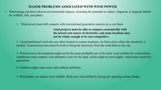
![Drag force (FD): It is described as follows, Where CD = drag coefficient and SD = Effective area of airfoil
in the direction of drag force.
CD = [FD/SD] / [(1/2) ρV2]](https://image.slidesharecdn.com/4thmodulences-read-only-241114035731-40b2fb17/85/4TH-MODULE-NCES-Read-Oaeryrhtrshnly-pptx-21-320.jpg)


![EEE 483[Wind Energy ,use of wind energy].pdf](https://cdn.slidesharecdn.com/ss_thumbnails/eee483windenergy-240506111938-7f084448-thumbnail.jpg?width=640&height=640&fit=bounds)


