Download to read offline
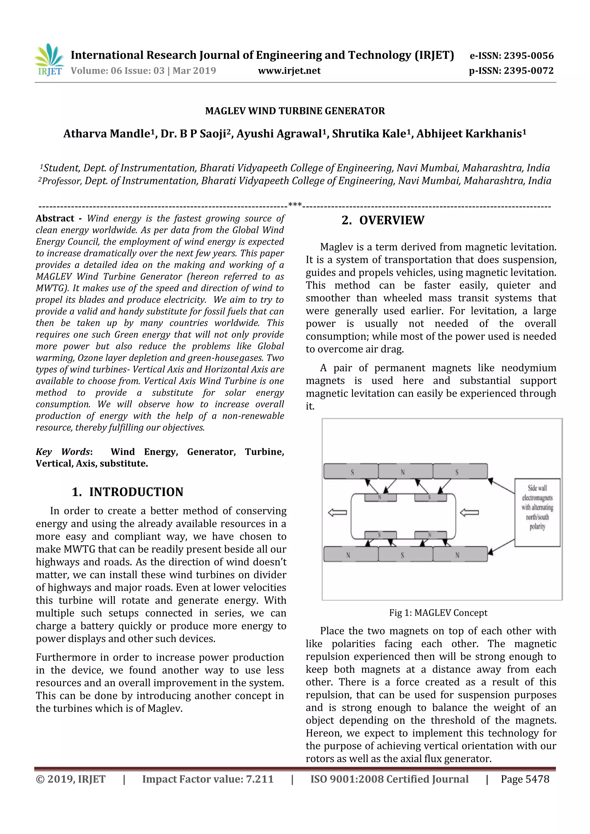


1) The document describes a proposed Maglev Wind Turbine Generator (MWTG) that uses magnetic levitation and vertical axis wind turbines to generate electricity from wind power more efficiently than traditional horizontal axis wind turbines. 2) The MWTG aims to provide a renewable energy alternative to fossil fuels by taking advantage of lower wind speeds using vertical axis turbines and reducing noise, maintenance needs, and land usage through magnetic levitation of components. 3) The proposed design of the MWTG includes 10 acrylic blades attached to a hollow aluminum shaft that spins magnets near coils to generate electricity through the principles of electromagnetic induction, with the goal of increasing overall energy production from wind in a more efficient manner.