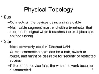
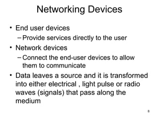
1© 2009, Cisco Systems, Inc. All rights reserved.
Module 2
Internetworking Devices
By Dr. Percy DIAS
2
Physical Topology
• Physical topology is the actual layout of the
wire or media.
3
Physical Topology
• Bus
–Connects all the devices using a single cable
–Main cable segment must end with a terminator that
absorbs the signal when it reaches the end (data can
bounces back)
• Star
–Most commonly used in Ethernet LAN
–Central connection point can be a hub, switch or
router, and might be desirable for security or restricted
access
–If the central device fails, the whole network becomes
disconnected
4
Physical Topology
• Ring
–Frame travels around the ring, stopped at
each node
–If a node wants to transmit data, it is
permitted to add data as well as destination
address
–Each device cleans up the signal, so fewer
repeaters are needed
5
Physical Topology
• Dual Ring
–If one ring fails, data can be transmitted on the
other ring
• Full-mesh
–Connect all devices to each other for
redundancy and fault tolerance
• Partial-mesh
–At least one device maintains multiple
connections to others
6
Logical Topology
• Logical topology of a network refers to the
logical paths that signals travel from one
point on the network to another
• Broadcast
– Ethernet
• Token Passing
– Controls network access by passing an
electronic token sequentially to each host
– Token Ring and FDDI are examples of Token
Passing on a physical ring topology
7
Collisions
• Hubs operate at Layer 1, simply repeating all
received signals out all other ports
8
Networking Devices
• End user devices
– Provide services directly to the user
• Network devices
– Connect the end-user devices to allow
them to communicate
• Data leaves a source and it is transformed
into either electrical , light pulse or radio
waves (signals) that pass along the
medium
9
Networking Devices
10
Repeated Ethernet Signal
11
Repeated Ethernet Signal
• Betty sends a clean signal
• The signal degrades by the time it reaches
the repeater
• The repeater regenerates a new, clean
signal and sends it out its other port
12
Repeaters
• When a signal is sent over a wire, it degrades
• To extend the distance of LANs, repeaters were
developed
• Typically had two ports connecting two different
Ethernet segments
• Interpreted the incoming signal on one port as
1’s and 0’s
• Sent a regenerated clean signal out the other
port
13
Repeaters: Layer 1
14
Hubs
• Regenerate
signals
• Used as network
concentration
points
• Multiport repeater
• Layer 1 device
15
Hub Operation
16
Network Interface Card
• Carries a unique code called a Media
Access Control (MAC)
• MAC address controls data communication
for the host on the network
• NICs are considered layer 2 and operate at
both layer 1 and 2 (Layer 1: send and
receive signals over an attached cable)
17
Bridges
Layer 2 device designed to create two or more LAN
segments, each of which is a separate collision domain
Bridges filter traffic
by looking at MAC
addresses.
18
Bridges
• Filter traffic on a LAN to keep local traffic
local yet allow connectivity to other parts
• Keep track of which MAC addresses are on
each side of the bridge and makes
forwarding decisions based on MAC address
table
• When a bridge receives a frame, the
destination MAC address is looked up in the
bridge table to determine whether to filter,
flood or forward the frame onto another
segment.
19
Bridges
20
Flooding Unknown Unicasts
21
Learning Table Entries and
Flooding Unknown Unicasts
• Switches and bridges learn entries in the
table dynamically
• They use this logic:
– Examine the source MAC address of the
frame and the interface on which it was
received
– Add that source MAC address and
corresponding interface to the table
22
Learning Content Addressable Memory
(CAM) Table Entries: Two Switches
SW2
23
Bridge Making Filter Decision
24
Bridge Making a Forwarding Decision
25
LAN Switches
• Layer 2 device
• Use a table of MAC addresses (switching table)
to determine the segment on which a frame
needs to be transmitted
• Cisco switching table sometimes referred to as
Content Addressable Memory (CAM).
• Switches operate at much higher speed than
bridges (hardware vs software)
• Each switch port acts as a separate bridge and
give each host the medium’s full bandwidth
(microsegmentation)
• Improve network performance: speed and
bandwidth
26
Switch Making a Forwarding Decision
27
28
Switch Buffering Example
Barney
29
Preventing Collisions with
Switch Buffering
• Switches prevent collisions by buffering
frames
• If several PCs send frames to the same
address at the same time, the switch holds
the frames in memory - a process called
buffering
• The switch then forwards the frames one
at a time
30
Routers
• Layer 3 device
• Use logical address (network layer
address)
• Can connect different layer 2 technologies
• Examine incoming packet (layer 3 data),
choose the best path, and switch them to
the proper outgoing port.
31
Cisco Academy 3 Reference
• CCNA1 Online Materials
• Slide 2 - 6: 2.1.4
• Slide 8-9, 26: 2.1.3
• Slide 12-14: 5.1.6-5.1.7
• Slide 16-19, 23-24, 26: 5.1.9-5.1.11
32
Cisco Academy 4 Exploration
Reference
Networking Fundamentals
• Slide 2 - 6: 9.1.1-9.1.3
• Slide 8-9,12-14, 26: 9.6.1-9.6.4
• Slide 16-19, 23-24, 26: 9.6.1-9.6.4
• Slide 14-15: 9.6.1-9.6.2

Internetworking devices(networking)

  • 1.
    1© 2009, CiscoSystems, Inc. All rights reserved. Module 2 Internetworking Devices By Dr. Percy DIAS
  • 2.
    2 Physical Topology • Physicaltopology is the actual layout of the wire or media.
  • 3.
    3 Physical Topology • Bus –Connectsall the devices using a single cable –Main cable segment must end with a terminator that absorbs the signal when it reaches the end (data can bounces back) • Star –Most commonly used in Ethernet LAN –Central connection point can be a hub, switch or router, and might be desirable for security or restricted access –If the central device fails, the whole network becomes disconnected
  • 4.
    4 Physical Topology • Ring –Frametravels around the ring, stopped at each node –If a node wants to transmit data, it is permitted to add data as well as destination address –Each device cleans up the signal, so fewer repeaters are needed
  • 5.
    5 Physical Topology • DualRing –If one ring fails, data can be transmitted on the other ring • Full-mesh –Connect all devices to each other for redundancy and fault tolerance • Partial-mesh –At least one device maintains multiple connections to others
  • 6.
    6 Logical Topology • Logicaltopology of a network refers to the logical paths that signals travel from one point on the network to another • Broadcast – Ethernet • Token Passing – Controls network access by passing an electronic token sequentially to each host – Token Ring and FDDI are examples of Token Passing on a physical ring topology
  • 7.
    7 Collisions • Hubs operateat Layer 1, simply repeating all received signals out all other ports
  • 8.
    8 Networking Devices • Enduser devices – Provide services directly to the user • Network devices – Connect the end-user devices to allow them to communicate • Data leaves a source and it is transformed into either electrical , light pulse or radio waves (signals) that pass along the medium
  • 9.
  • 10.
  • 11.
    11 Repeated Ethernet Signal •Betty sends a clean signal • The signal degrades by the time it reaches the repeater • The repeater regenerates a new, clean signal and sends it out its other port
  • 12.
    12 Repeaters • When asignal is sent over a wire, it degrades • To extend the distance of LANs, repeaters were developed • Typically had two ports connecting two different Ethernet segments • Interpreted the incoming signal on one port as 1’s and 0’s • Sent a regenerated clean signal out the other port
  • 13.
  • 14.
    14 Hubs • Regenerate signals • Usedas network concentration points • Multiport repeater • Layer 1 device
  • 15.
  • 16.
    16 Network Interface Card •Carries a unique code called a Media Access Control (MAC) • MAC address controls data communication for the host on the network • NICs are considered layer 2 and operate at both layer 1 and 2 (Layer 1: send and receive signals over an attached cable)
  • 17.
    17 Bridges Layer 2 devicedesigned to create two or more LAN segments, each of which is a separate collision domain Bridges filter traffic by looking at MAC addresses.
  • 18.
    18 Bridges • Filter trafficon a LAN to keep local traffic local yet allow connectivity to other parts • Keep track of which MAC addresses are on each side of the bridge and makes forwarding decisions based on MAC address table • When a bridge receives a frame, the destination MAC address is looked up in the bridge table to determine whether to filter, flood or forward the frame onto another segment.
  • 19.
  • 20.
  • 21.
    21 Learning Table Entriesand Flooding Unknown Unicasts • Switches and bridges learn entries in the table dynamically • They use this logic: – Examine the source MAC address of the frame and the interface on which it was received – Add that source MAC address and corresponding interface to the table
  • 22.
    22 Learning Content AddressableMemory (CAM) Table Entries: Two Switches SW2
  • 23.
  • 24.
    24 Bridge Making aForwarding Decision
  • 25.
    25 LAN Switches • Layer2 device • Use a table of MAC addresses (switching table) to determine the segment on which a frame needs to be transmitted • Cisco switching table sometimes referred to as Content Addressable Memory (CAM). • Switches operate at much higher speed than bridges (hardware vs software) • Each switch port acts as a separate bridge and give each host the medium’s full bandwidth (microsegmentation) • Improve network performance: speed and bandwidth
  • 26.
    26 Switch Making aForwarding Decision
  • 27.
  • 28.
  • 29.
    29 Preventing Collisions with SwitchBuffering • Switches prevent collisions by buffering frames • If several PCs send frames to the same address at the same time, the switch holds the frames in memory - a process called buffering • The switch then forwards the frames one at a time
  • 30.
    30 Routers • Layer 3device • Use logical address (network layer address) • Can connect different layer 2 technologies • Examine incoming packet (layer 3 data), choose the best path, and switch them to the proper outgoing port.
  • 31.
    31 Cisco Academy 3Reference • CCNA1 Online Materials • Slide 2 - 6: 2.1.4 • Slide 8-9, 26: 2.1.3 • Slide 12-14: 5.1.6-5.1.7 • Slide 16-19, 23-24, 26: 5.1.9-5.1.11
  • 32.
    32 Cisco Academy 4Exploration Reference Networking Fundamentals • Slide 2 - 6: 9.1.1-9.1.3 • Slide 8-9,12-14, 26: 9.6.1-9.6.4 • Slide 16-19, 23-24, 26: 9.6.1-9.6.4 • Slide 14-15: 9.6.1-9.6.2