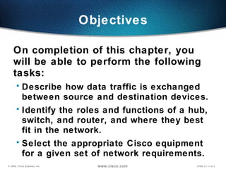
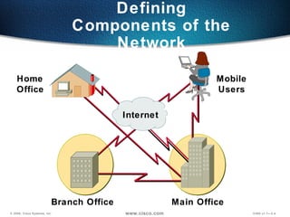
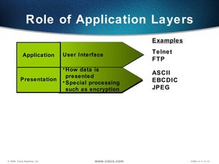
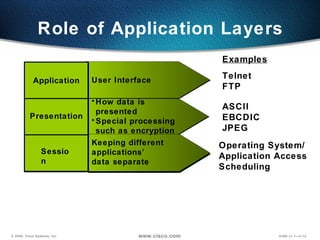
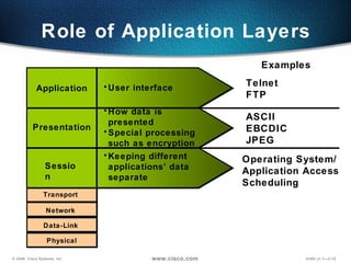
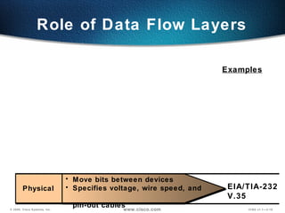
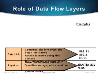
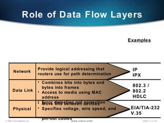
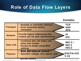
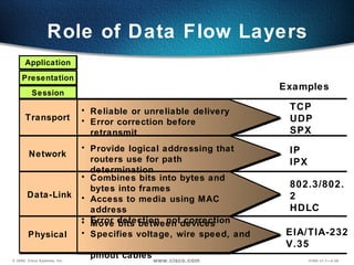
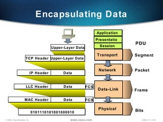
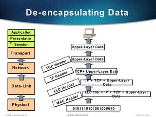
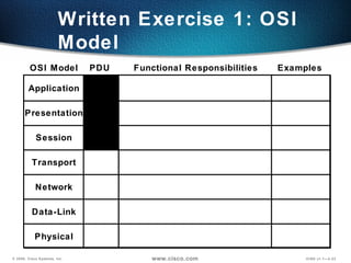
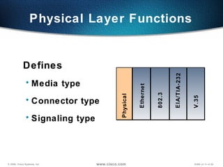
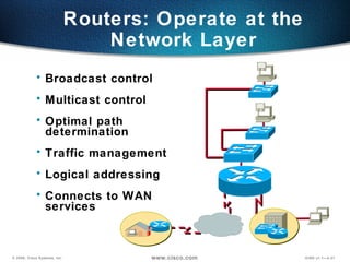
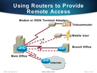
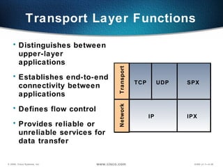
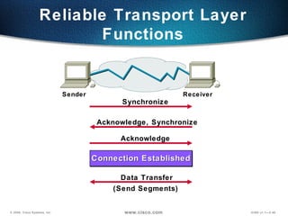
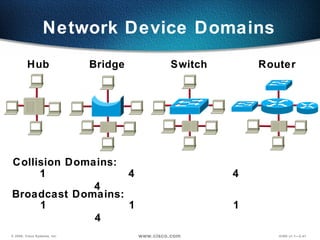
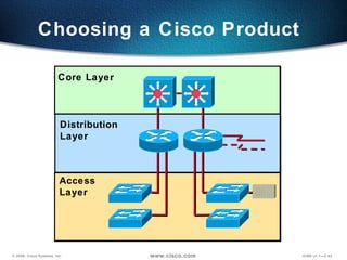
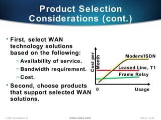
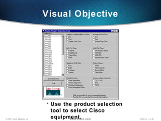
http://cisco-training640-802.blogspot.com/ Internetworking Concepts Overview
Overflow text
Objectives On completion of this chapter, you will be able to perform the following tasks: Describe how data traffic is exchanged between source and destination devices. Identify the roles and functions of a hub, switch, and router, and where they best fit in the network. Select the appropriate Cisco equipment for a given set of network requirements.
Defining Components of the Network Main Office Branch Office   Home  Office   Mobile Users Internet
Defining Components of the Network (cont.) Floor 2 Floor 1 Server Farm Branch Office Telecommuter ISDN Remote Campus
Network Structure Defined by Hierarchy  Distribution  Layer Core Layer Access Layer
Access Layer Characteristics End-station entry point to the network Access Layer
Distribution Layer Characteristics Access layer  aggregation point Traffic routing Broadcast/multicast  domains Media translation Security Possible point for remote access Distribution Layer
Core Layer Characteristics  Fast transport to enterprise services No packet manipulation Core Layer
OSI Model Overview Application  (Upper)  Layers Session Presentation Application
OSI Model Overview Data Flow  Layers Transport Data-Link  Network Physical Application  (Upper)  Layers Session Presentation Application
Role of Application Layers Telnet FTP User Interface Examples Application
Role of Application Layers Telnet FTP ASCII EBCDIC JPEG User Interface How data is presented Special processing such as encryption Examples Presentation Application
Role of Application Layers Telnet FTP ASCII EBCDIC JPEG Keeping different applications’  data separate User Interface How data is presented Special processing such as encryption Operating System/ Application Access  Scheduling Examples Session Presentation Application
Role of Application Layers Keeping different applications’ data separate User interface How data is presented Special processing such as encryption Transport Data-Link  Network Physical Examples Session Presentation Application Telnet FTP ASCII EBCDIC JPEG Operating System/ Application Access  Scheduling
Role of Data Flow Layers EIA/TIA-232 V.35 Examples Physical  Move bits between devices Specifies voltage, wire speed, and  pin-out cables
Role of Data Flow Layers 802.3 / 802.2 HDLC EIA/TIA-232 V.35 Examples Data Link Physical  Combines bits into bytes and  bytes into frames Access to media using MAC address Error detection not correction Move bits between devices Specifies voltage, wire speed, and  pin-out cables
Role of Data Flow Layers 802.3 / 802.2 HDLC EIA/TIA-232 V.35 IP IPX Examples Network  Data Link Physical  Combines bits into bytes and  bytes into frames Access to media using MAC address Error detection not correction Move bits between devices Specifies voltage, wire speed, and  pin-out cables Provide logical addressing that routers use for path determination
Role of Data Flow Layers TCP UDP SPX 802.3 / 802.2 HDLC EIA/TIA-232 V.35 IP IPX Examples Transport  Data Link Physical  Reliable or unreliable delivery Error correction before retransmit Combines bits into bytes and  bytes into frames Access to media using MAC address Error detection not correction Move bits between devices Specifies voltage, wire speed, and  pin-out cables Network  Provide logical addressing that routers use for path determination
Role of Data Flow Layers TCP UDP SPX 802.3/802.2 HDLC EIA/TIA-232 V.35 IP IPX Presentation Application Session Examples Reliable or unreliable delivery Error correction before retransmit Combines bits into bytes and  bytes into frames Access to media using MAC address Error detection, not correction Move bits between devices Specifies voltage, wire speed, and  pinout cables Transport  Data-Link Physical  Network  Provide logical addressing that routers use for path determination
Encapsulating Data Transport  Data-Link Physical  Network  Upper-Layer Data Upper-Layer Data TCP Header Data IP Header Data LLC Header 0101110101001000010 Data MAC Header Presentation Application Session Segment Packet Bits Frame PDU FCS FCS
Upper-Layer Data De-encapsulating Data LLC Hdr + IP + TCP + Upper-Layer Data MAC Header IP + TCP + Upper-Layer Data LLC Header TCP+ Upper-Layer Data IP Header Upper-Layer Data TCP Header 0101110101001000010 Transport  Data-Link Physical  Network  Presentation Application Session
Application Presentation Session Transport Network Data-Link Physical OSI Model PDU Functional Responsibilities Examples Written Exercise 1: OSI Model
Physical Layer Functions Defines Media type  Connector type  Signaling type Ethernet 802.3 V.35 Physical EIA/TIA-232
Physical Layer: Ethernet/802.3 Hub Hosts Host 10Base2—Thin Ethernet 10Base5—Thick Ethernet 10BaseT—Twisted Pair
Hubs Operate at Physical Layer Physical  All devices are in the same collision domain. All devices are in the same broadcast domain. Devices share the same bandwidth. A B C D
Hubs: One Collision Domain More end stations means more collisions. CSMA/CD is used.
Data-Link Layer Functions Defines: Physical source and  destination addresses Higher-layer protocol  (service access point) associated with frame  Network topology  Frame sequencing Flow control Connection-oriented  or connectionless Data-Link Physical EIA/TIA-232 V.35 Ethernet Frame Relay HDLC 802.2 802.3
Data Source Address FCS Length Destination Address Variable 2 6 6 4 0000.0C  xx.xxxx Vendor Assigned IEEE Assigned MAC Layer—802.3 Data-Link Layer Functions (cont.) Preamble Ethernet II uses “Type” here and  does not use 802.2. MAC Address 8 Number of Bytes
Data Destination  SAP Source  SAP Data Source Address FCS Length Destination Address Variable 1 1 802.2 (SAP) MAC Layer—802.3 Data-Link Layer Functions (cont.) Control 1 or 2 3 2 Preamble Data Destination SAP AA Source SAP AA Variable 1 1 802.2 (SNAP) Control 03 1 or 2 OR OUI  ID Type Number of Bytes Number of Bytes
Each segment has its own collision domain. All segments are in the same broadcast domain. Data-Link Switches and Bridges Operate at Data-Link Layer OR 1 2 3 1 2 4
Switches Each segment is its own collision domain. Broadcasts are forwarded to all segments. Memory Switch
Network Layer Functions Defines logical source and destination addresses associated with a specific protocol Defines paths through network Interconnects multiple data links Network IP, IPX Data-Link Physical EIA/TIA-232 V.35 Ethernet Frame Relay HDLC 802.2 802.3
Data Source Address Destination  Address IP Network Layer Functions (cont.) Header 172.15.1.1 Node Network Logical Address Network Layer End-Station Packet
Network Layer Functions (cont.) 11111111 11111111 00000000 00000000 10101100 00010000 01111010 11001100 Binary Mask Binary Address 172.16.122.204 255.255.0.0 172 16 122 204 255 Address Mask 255 0 0 Network Host
Routing Table NET INT Metric 1 2 4 S0 S0 E0 1 0 0 1.0 4.0 1.3 E0 4.3 S0 2.2 E0 2.1 S0 4.1 4.2 1.1 1.2 Routing Table NET INT Metric 1 2 4 E0 S0 S0 0 0 1 Logical addressing allows for hierarchical network. Configuration is required. Configured information identifies paths to networks. Network Layer Functions (cont.)
Routers: Operate at the Network Layer Broadcast control Multicast control Optimal path determination Traffic management Logical addressing Connects to WAN  services
Using Routers to Provide Remote Access Internet Telecommuter Branch Office Modem or ISDN Terminal Adapter Mobile User Main Office
Transport Layer Functions Distinguishes between upper-layer applications Establishes end-to-end connectivity between applications Defines flow control  Provides reliable or unreliable services for data transfer Network IPX IP Transport SPX TCP UDP
Reliable Transport Layer Functions Synchronize Acknowledge, Synchronize Acknowledge Data Transfer (Send Segments) Sender Receiver Connection Established
Network Device Domains Hub Bridge Switch Router Collision Domains: 1  4  4  4  Broadcast Domains: 1  1  1  4
Choosing a Cisco Product  Distribution  Layer Core Layer Access Layer
Product Selection Considerations Functionality and features you need today Capacity and performance  Easy installation and centralized management Network resiliency  Investment protection in existing infrastructure Migration path for change and growth Seamless access for mobile users and  branch offices
First, select WAN  technology solutions  based on the following: Availability of service. Bandwidth requirement. Cost. Second, choose products  that support selected WAN solutions. Product Selection Considerations (cont.) Cost per Month Usage Leased Line, T1 Modem/ISDN Frame Relay 0
Product Selection Considerations (cont.) 1544 128 64 56 19.2 9.6 4.8 Determine applications that you want to run. ISDN,  Frame Relay Old Modem Telnet New Modem Web Browsing Voice Video, Multimedia E-Mail, File Transfer Leased Line, Frame Relay, xDSL kbps
Cisco Hub Products Selection Issues: Need for 10 Mbps or 100 Mbps on media Port density Need for management console Easy operations Cisco 1500 Micro Hub Cisco FastHub300 Cisco 1528 Micro Hub 10/100 Cisco FastHub400 Cisco FastHub200 Cisco FastHub®100
Cisco Switch Products Selection Issues: Need for 10 Mbps, 100 Mbps, or 1000 Mbps on media Need for trunking and Inter-Switch Links Workgroup segmentation (VLANs) Port density needs Different user interfaces   Desktop/Workgroup  Solutions Wiring  Closet/Backbone  Solutions Cisco 1548 Micro  Switch 10/100 Catalyst  3000 Series Catalyst 2900 Series XL Catalyst®  1900/2820 Series Catalyst  2900 Series Catalyst  5000 Series Catalyst  8500 Series
Do Not Delete—Overflow Text on Notes Page
Cisco Router Products Selection Issues: Scale of the routing features needed Port density/variety requirements Capacity and performance  Common user interface Cisco 700/800 Series Cisco 1600/1700  Series Cisco 2500  Series Cisco 3600  Series AS 5000  Series Small Office Solutions Branch Office Solutions Central Site Solutions Cisco 12000 GSR  Series Cisco 4000  Series Cisco 7000 Series Home Office Solutions Cisco 2600  Series
Do Not Delete—Overflow Text on Notes Page
Visual Objective Use the product selection tool to select Cisco equipment.
Summary After completing this chapter, you should be able to perform the following tasks: Describe how data moves through a network. Identify the roles and functions of routers, switches, and hubs, and specify where each device best fits in the network. Select the appropriate Cisco equipment for a network that combines switching, routing, and remote access requirements.
1.   What are some of the advantages of using the OSI model in a networking environment? 2. Describe the encapsulation process. 3. How many broadcast and collision domains are on a hub? Review Questions
Blank for Pagination

Internetworking Overview

  • 1.
  • 2.
  • 3.
    Objectives On completionof this chapter, you will be able to perform the following tasks: Describe how data traffic is exchanged between source and destination devices. Identify the roles and functions of a hub, switch, and router, and where they best fit in the network. Select the appropriate Cisco equipment for a given set of network requirements.
  • 4.
    Defining Components ofthe Network Main Office Branch Office Home Office Mobile Users Internet
  • 5.
    Defining Components ofthe Network (cont.) Floor 2 Floor 1 Server Farm Branch Office Telecommuter ISDN Remote Campus
  • 6.
    Network Structure Definedby Hierarchy Distribution Layer Core Layer Access Layer
  • 7.
    Access Layer CharacteristicsEnd-station entry point to the network Access Layer
  • 8.
    Distribution Layer CharacteristicsAccess layer aggregation point Traffic routing Broadcast/multicast domains Media translation Security Possible point for remote access Distribution Layer
  • 9.
    Core Layer Characteristics Fast transport to enterprise services No packet manipulation Core Layer
  • 10.
    OSI Model OverviewApplication (Upper) Layers Session Presentation Application
  • 11.
    OSI Model OverviewData Flow Layers Transport Data-Link Network Physical Application (Upper) Layers Session Presentation Application
  • 12.
    Role of ApplicationLayers Telnet FTP User Interface Examples Application
  • 13.
    Role of ApplicationLayers Telnet FTP ASCII EBCDIC JPEG User Interface How data is presented Special processing such as encryption Examples Presentation Application
  • 14.
    Role of ApplicationLayers Telnet FTP ASCII EBCDIC JPEG Keeping different applications’ data separate User Interface How data is presented Special processing such as encryption Operating System/ Application Access Scheduling Examples Session Presentation Application
  • 15.
    Role of ApplicationLayers Keeping different applications’ data separate User interface How data is presented Special processing such as encryption Transport Data-Link Network Physical Examples Session Presentation Application Telnet FTP ASCII EBCDIC JPEG Operating System/ Application Access Scheduling
  • 16.
    Role of DataFlow Layers EIA/TIA-232 V.35 Examples Physical Move bits between devices Specifies voltage, wire speed, and pin-out cables
  • 17.
    Role of DataFlow Layers 802.3 / 802.2 HDLC EIA/TIA-232 V.35 Examples Data Link Physical Combines bits into bytes and bytes into frames Access to media using MAC address Error detection not correction Move bits between devices Specifies voltage, wire speed, and pin-out cables
  • 18.
    Role of DataFlow Layers 802.3 / 802.2 HDLC EIA/TIA-232 V.35 IP IPX Examples Network Data Link Physical Combines bits into bytes and bytes into frames Access to media using MAC address Error detection not correction Move bits between devices Specifies voltage, wire speed, and pin-out cables Provide logical addressing that routers use for path determination
  • 19.
    Role of DataFlow Layers TCP UDP SPX 802.3 / 802.2 HDLC EIA/TIA-232 V.35 IP IPX Examples Transport Data Link Physical Reliable or unreliable delivery Error correction before retransmit Combines bits into bytes and bytes into frames Access to media using MAC address Error detection not correction Move bits between devices Specifies voltage, wire speed, and pin-out cables Network Provide logical addressing that routers use for path determination
  • 20.
    Role of DataFlow Layers TCP UDP SPX 802.3/802.2 HDLC EIA/TIA-232 V.35 IP IPX Presentation Application Session Examples Reliable or unreliable delivery Error correction before retransmit Combines bits into bytes and bytes into frames Access to media using MAC address Error detection, not correction Move bits between devices Specifies voltage, wire speed, and pinout cables Transport Data-Link Physical Network Provide logical addressing that routers use for path determination
  • 21.
    Encapsulating Data Transport Data-Link Physical Network Upper-Layer Data Upper-Layer Data TCP Header Data IP Header Data LLC Header 0101110101001000010 Data MAC Header Presentation Application Session Segment Packet Bits Frame PDU FCS FCS
  • 22.
    Upper-Layer Data De-encapsulatingData LLC Hdr + IP + TCP + Upper-Layer Data MAC Header IP + TCP + Upper-Layer Data LLC Header TCP+ Upper-Layer Data IP Header Upper-Layer Data TCP Header 0101110101001000010 Transport Data-Link Physical Network Presentation Application Session
  • 23.
    Application Presentation SessionTransport Network Data-Link Physical OSI Model PDU Functional Responsibilities Examples Written Exercise 1: OSI Model
  • 24.
    Physical Layer FunctionsDefines Media type Connector type Signaling type Ethernet 802.3 V.35 Physical EIA/TIA-232
  • 25.
    Physical Layer: Ethernet/802.3Hub Hosts Host 10Base2—Thin Ethernet 10Base5—Thick Ethernet 10BaseT—Twisted Pair
  • 26.
    Hubs Operate atPhysical Layer Physical All devices are in the same collision domain. All devices are in the same broadcast domain. Devices share the same bandwidth. A B C D
  • 27.
    Hubs: One CollisionDomain More end stations means more collisions. CSMA/CD is used.
  • 28.
    Data-Link Layer FunctionsDefines: Physical source and destination addresses Higher-layer protocol (service access point) associated with frame Network topology Frame sequencing Flow control Connection-oriented or connectionless Data-Link Physical EIA/TIA-232 V.35 Ethernet Frame Relay HDLC 802.2 802.3
  • 29.
    Data Source AddressFCS Length Destination Address Variable 2 6 6 4 0000.0C xx.xxxx Vendor Assigned IEEE Assigned MAC Layer—802.3 Data-Link Layer Functions (cont.) Preamble Ethernet II uses “Type” here and does not use 802.2. MAC Address 8 Number of Bytes
  • 30.
    Data Destination SAP Source SAP Data Source Address FCS Length Destination Address Variable 1 1 802.2 (SAP) MAC Layer—802.3 Data-Link Layer Functions (cont.) Control 1 or 2 3 2 Preamble Data Destination SAP AA Source SAP AA Variable 1 1 802.2 (SNAP) Control 03 1 or 2 OR OUI ID Type Number of Bytes Number of Bytes
  • 31.
    Each segment hasits own collision domain. All segments are in the same broadcast domain. Data-Link Switches and Bridges Operate at Data-Link Layer OR 1 2 3 1 2 4
  • 32.
    Switches Each segmentis its own collision domain. Broadcasts are forwarded to all segments. Memory Switch
  • 33.
    Network Layer FunctionsDefines logical source and destination addresses associated with a specific protocol Defines paths through network Interconnects multiple data links Network IP, IPX Data-Link Physical EIA/TIA-232 V.35 Ethernet Frame Relay HDLC 802.2 802.3
  • 34.
    Data Source AddressDestination Address IP Network Layer Functions (cont.) Header 172.15.1.1 Node Network Logical Address Network Layer End-Station Packet
  • 35.
    Network Layer Functions(cont.) 11111111 11111111 00000000 00000000 10101100 00010000 01111010 11001100 Binary Mask Binary Address 172.16.122.204 255.255.0.0 172 16 122 204 255 Address Mask 255 0 0 Network Host
  • 36.
    Routing Table NETINT Metric 1 2 4 S0 S0 E0 1 0 0 1.0 4.0 1.3 E0 4.3 S0 2.2 E0 2.1 S0 4.1 4.2 1.1 1.2 Routing Table NET INT Metric 1 2 4 E0 S0 S0 0 0 1 Logical addressing allows for hierarchical network. Configuration is required. Configured information identifies paths to networks. Network Layer Functions (cont.)
  • 37.
    Routers: Operate atthe Network Layer Broadcast control Multicast control Optimal path determination Traffic management Logical addressing Connects to WAN services
  • 38.
    Using Routers toProvide Remote Access Internet Telecommuter Branch Office Modem or ISDN Terminal Adapter Mobile User Main Office
  • 39.
    Transport Layer FunctionsDistinguishes between upper-layer applications Establishes end-to-end connectivity between applications Defines flow control Provides reliable or unreliable services for data transfer Network IPX IP Transport SPX TCP UDP
  • 40.
    Reliable Transport LayerFunctions Synchronize Acknowledge, Synchronize Acknowledge Data Transfer (Send Segments) Sender Receiver Connection Established
  • 41.
    Network Device DomainsHub Bridge Switch Router Collision Domains: 1 4 4 4 Broadcast Domains: 1 1 1 4
  • 42.
    Choosing a CiscoProduct Distribution Layer Core Layer Access Layer
  • 43.
    Product Selection ConsiderationsFunctionality and features you need today Capacity and performance Easy installation and centralized management Network resiliency Investment protection in existing infrastructure Migration path for change and growth Seamless access for mobile users and branch offices
  • 44.
    First, select WAN technology solutions based on the following: Availability of service. Bandwidth requirement. Cost. Second, choose products that support selected WAN solutions. Product Selection Considerations (cont.) Cost per Month Usage Leased Line, T1 Modem/ISDN Frame Relay 0
  • 45.
    Product Selection Considerations(cont.) 1544 128 64 56 19.2 9.6 4.8 Determine applications that you want to run. ISDN, Frame Relay Old Modem Telnet New Modem Web Browsing Voice Video, Multimedia E-Mail, File Transfer Leased Line, Frame Relay, xDSL kbps
  • 46.
    Cisco Hub ProductsSelection Issues: Need for 10 Mbps or 100 Mbps on media Port density Need for management console Easy operations Cisco 1500 Micro Hub Cisco FastHub300 Cisco 1528 Micro Hub 10/100 Cisco FastHub400 Cisco FastHub200 Cisco FastHub®100
  • 47.
    Cisco Switch ProductsSelection Issues: Need for 10 Mbps, 100 Mbps, or 1000 Mbps on media Need for trunking and Inter-Switch Links Workgroup segmentation (VLANs) Port density needs Different user interfaces Desktop/Workgroup Solutions Wiring Closet/Backbone Solutions Cisco 1548 Micro Switch 10/100 Catalyst 3000 Series Catalyst 2900 Series XL Catalyst® 1900/2820 Series Catalyst 2900 Series Catalyst 5000 Series Catalyst 8500 Series
  • 48.
    Do Not Delete—OverflowText on Notes Page
  • 49.
    Cisco Router ProductsSelection Issues: Scale of the routing features needed Port density/variety requirements Capacity and performance Common user interface Cisco 700/800 Series Cisco 1600/1700 Series Cisco 2500 Series Cisco 3600 Series AS 5000 Series Small Office Solutions Branch Office Solutions Central Site Solutions Cisco 12000 GSR Series Cisco 4000 Series Cisco 7000 Series Home Office Solutions Cisco 2600 Series
  • 50.
    Do Not Delete—OverflowText on Notes Page
  • 51.
    Visual Objective Usethe product selection tool to select Cisco equipment.
  • 52.
    Summary After completingthis chapter, you should be able to perform the following tasks: Describe how data moves through a network. Identify the roles and functions of routers, switches, and hubs, and specify where each device best fits in the network. Select the appropriate Cisco equipment for a network that combines switching, routing, and remote access requirements.
  • 53.
    1. What are some of the advantages of using the OSI model in a networking environment? 2. Describe the encapsulation process. 3. How many broadcast and collision domains are on a hub? Review Questions
  • 54.

Editor's Notes

  • #2 Purpose: This chapter reviews general networking theory and introduces students to a portion of the Cisco product line. Timing: This chapter takes approximately 1.5 hours to present. Note: This section has a product selection tool laboratory exercise at the end. Contents: Objectives—This section explains what the student will be able to do at the end of this chapter. Defining Network Components—This section displays where devices are placed in the network. Mapping Business Needs to a Hierarchical Model—This section describes the hierarchical model used in network design. OSI Model Overview—This section reviews the OSI model. Communicating Between Layers—This section describes encapsulation and de-encapsulation. Written Exercise 1—This section has a written exercise to test the students’ knowledge of the OSI model. Physical Layer Functions—This section describes the physical layer of the OSI model. Data Link Layer Functions—This section describes the data link layer of the OSI model. Network Layer Functions—This section describes the network layer of the OSI model. Transport Layer Functions—This section describes the transport layer of the OSI model.