Downloaded 207 times
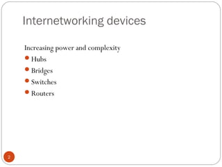
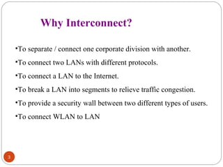
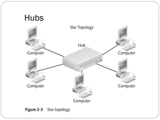
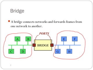
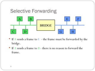
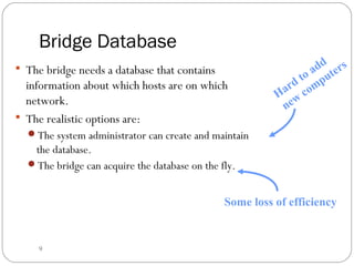
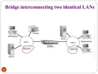
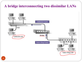
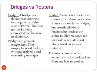

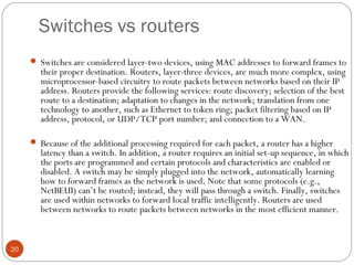
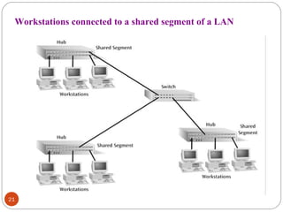
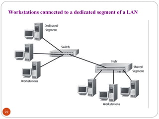
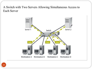
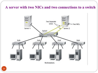
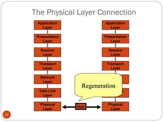
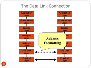
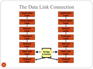
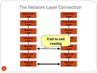
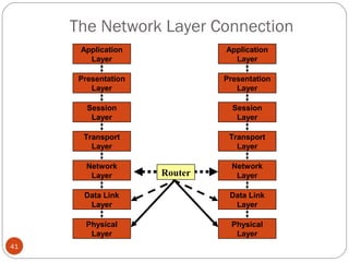

This document discusses different types of internetworking devices used to connect local area networks (LANs). It describes hubs, bridges, switches and routers in increasing order of complexity. Hubs simply repeat and broadcast data to all ports, while bridges learn and filter traffic between connected LANs. Switches operate similarly to bridges but provide dedicated connections for each workstation. Routers connect distinct networks like a LAN to the Internet, and make routing decisions based on IP addresses. The document outlines reasons for interconnecting LANs and the functions of various internetworking devices.