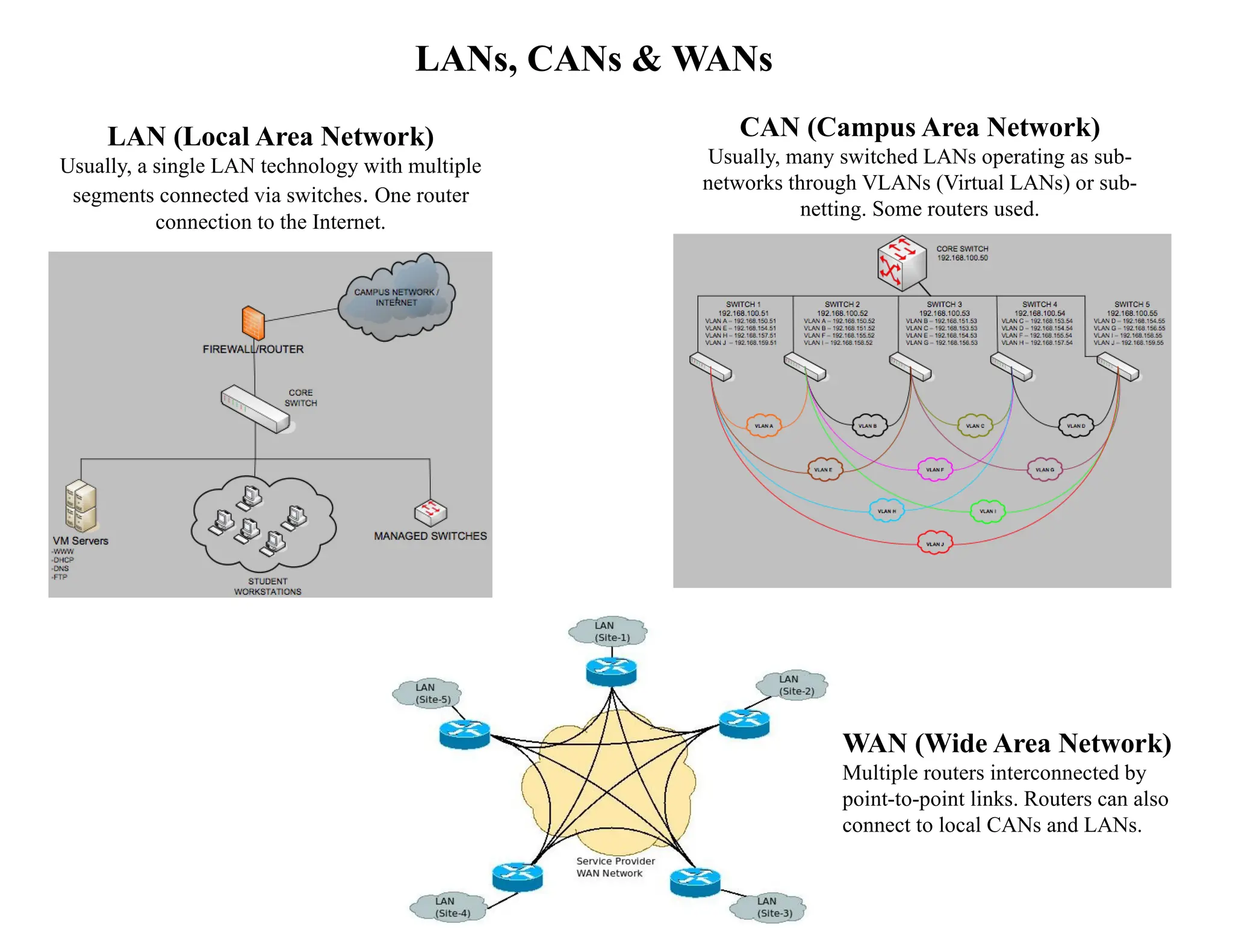
LANs, CANs &WANs
LAN (Local Area Network)
Usually, a single LAN technology with multiple
segments connected via switches. One router
connection to the Internet.
CAN (Campus Area Network)
Usually, many switched LANs operating as sub-
networks through VLANs (Virtual LANs) or sub-
netting. Some routers used.
WAN (Wide Area Network)
Multiple routers interconnected by
point-to-point links. Routers can also
connect to local CANs and LANs.
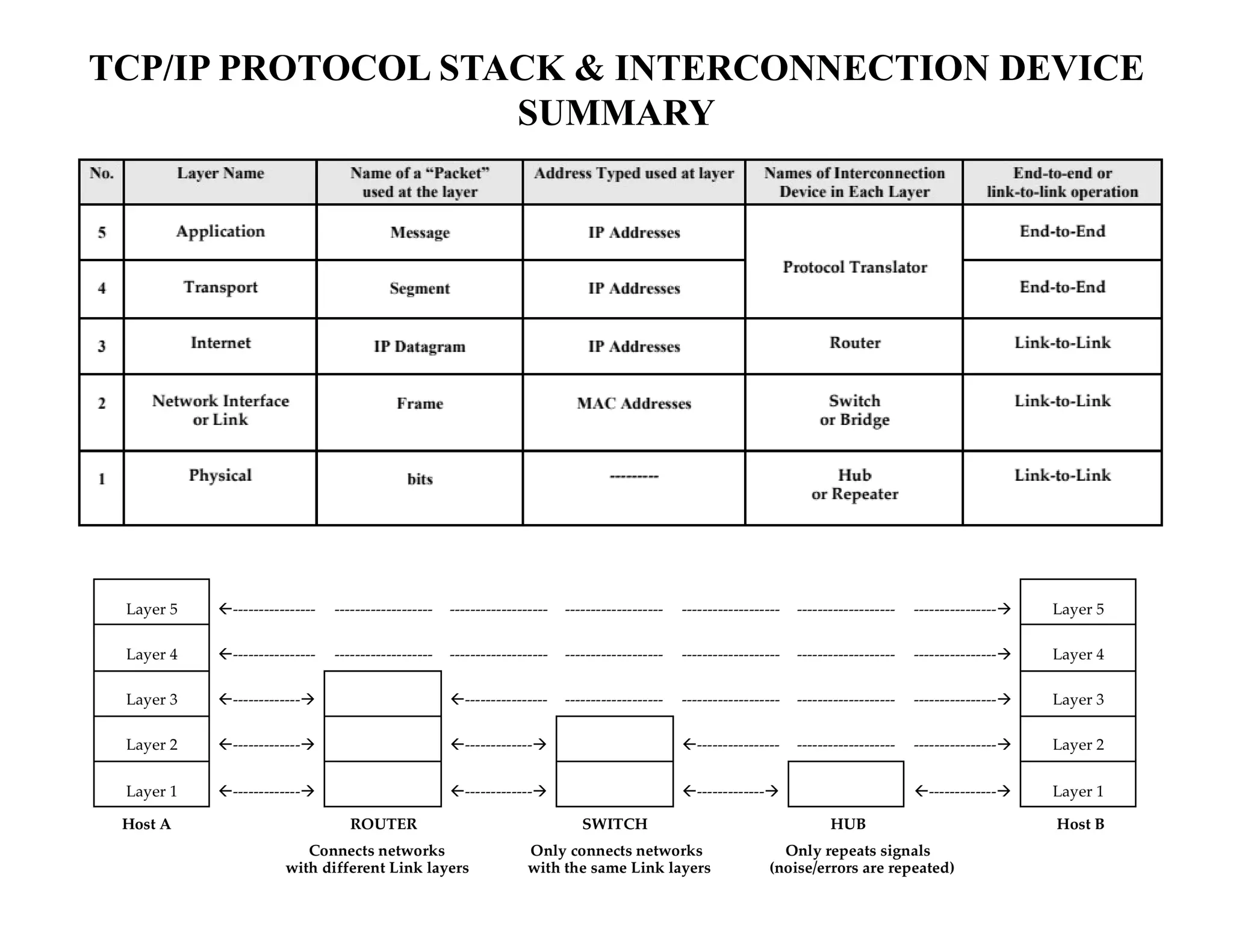
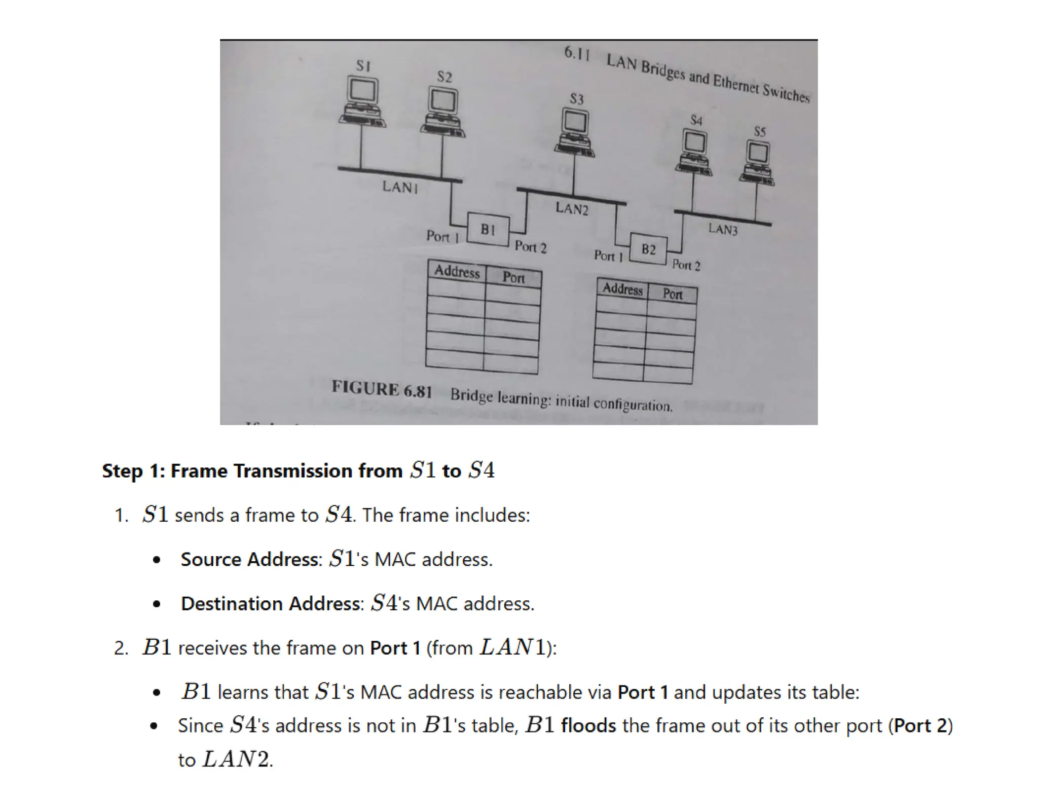
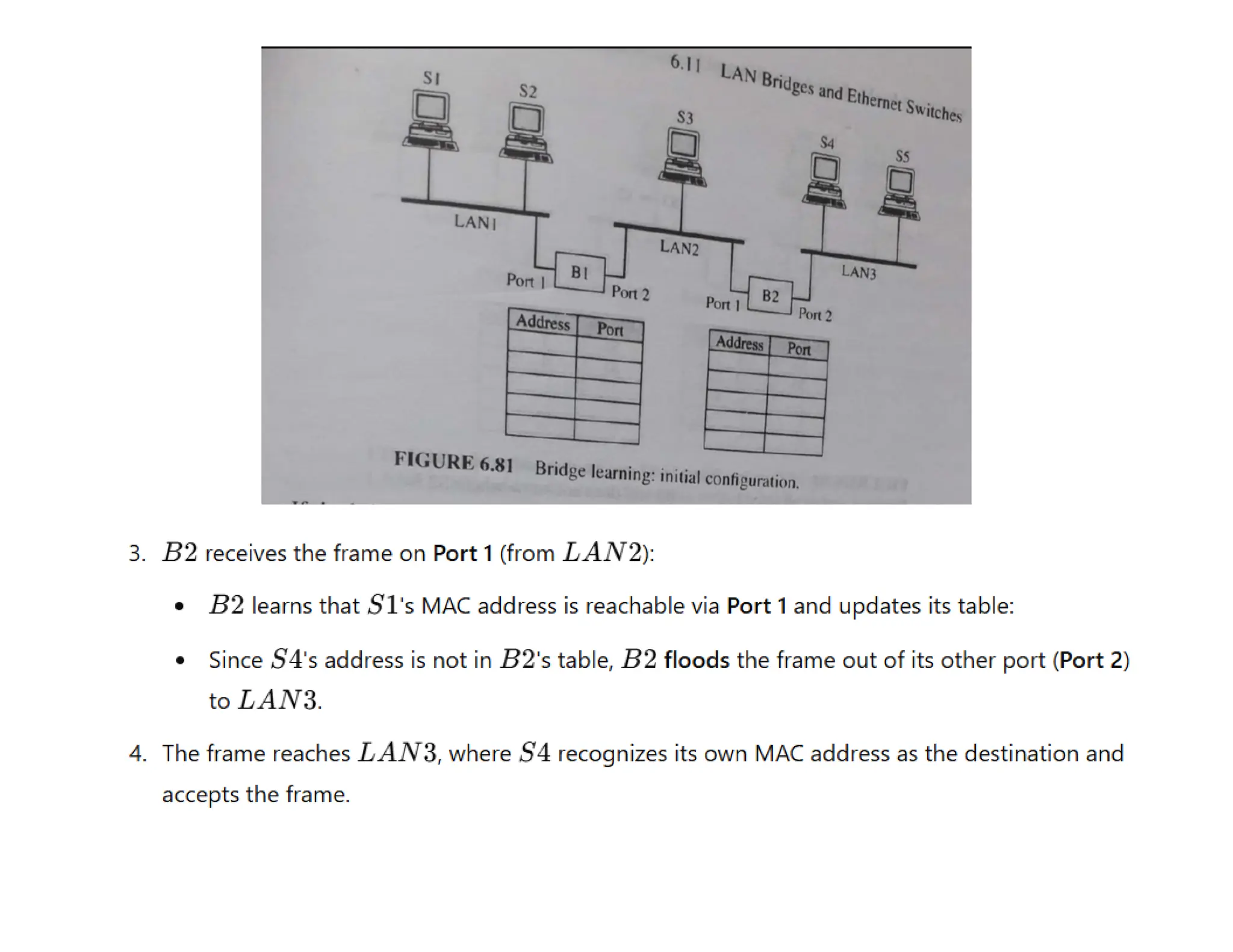
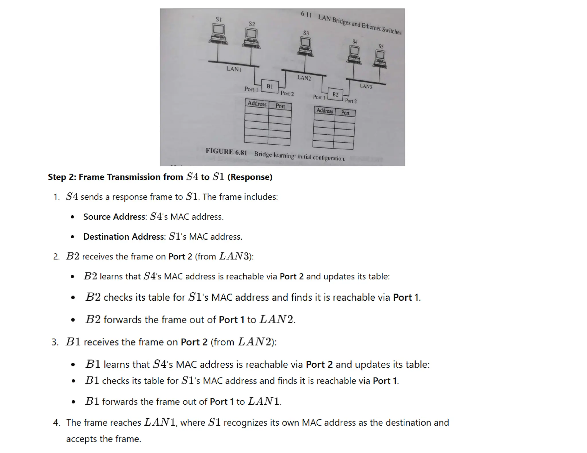
2.
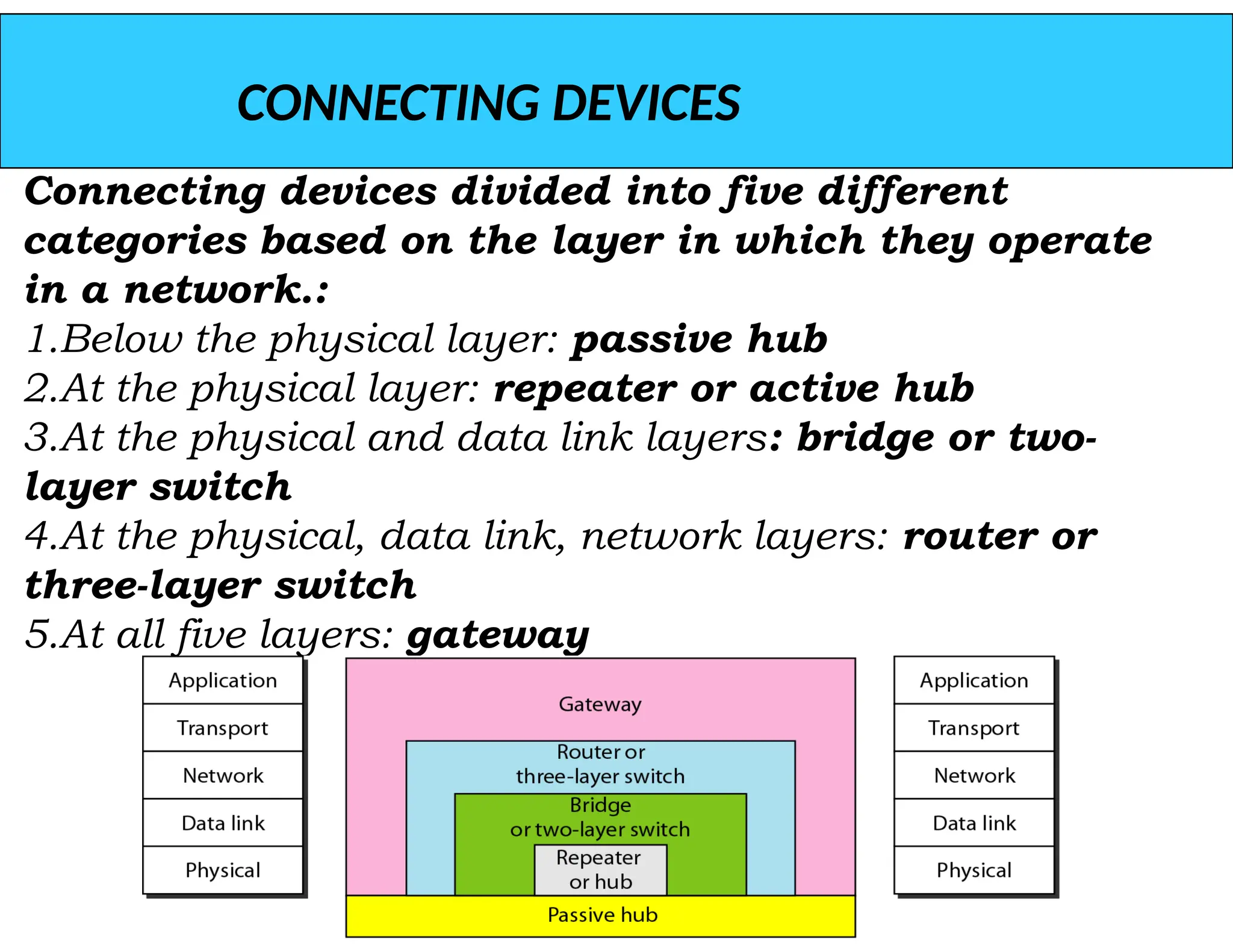
CONNECTING DEVICES
Connecting devicesdivided into five different
categories based on the layer in which they operate
in a network.:
1.Below the physical layer: passive hub
2.At the physical layer: repeater or active hub
3.At the physical and data link layers: bridge or two-
layer switch
4.At the physical, data link, network layers: router or
three-layer switch
5.At all five layers: gateway
3.
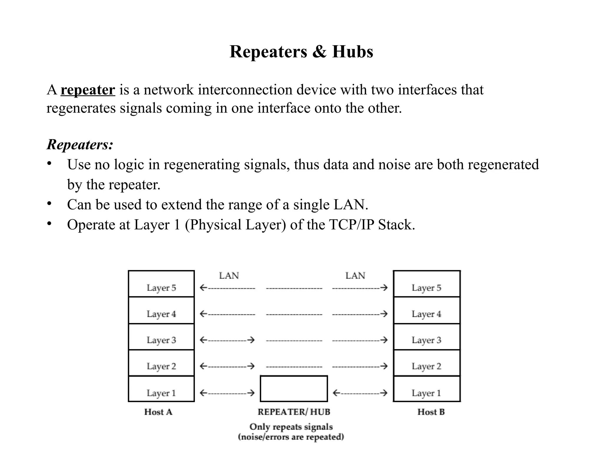
Repeaters & Hubs
Arepeater is a network interconnection device with two interfaces that
regenerates signals coming in one interface onto the other.
Repeaters:
• Use no logic in regenerating signals, thus data and noise are both regenerated
by the repeater.
• Can be used to extend the range of a single LAN.
• Operate at Layer 1 (Physical Layer) of the TCP/IP Stack.
4.
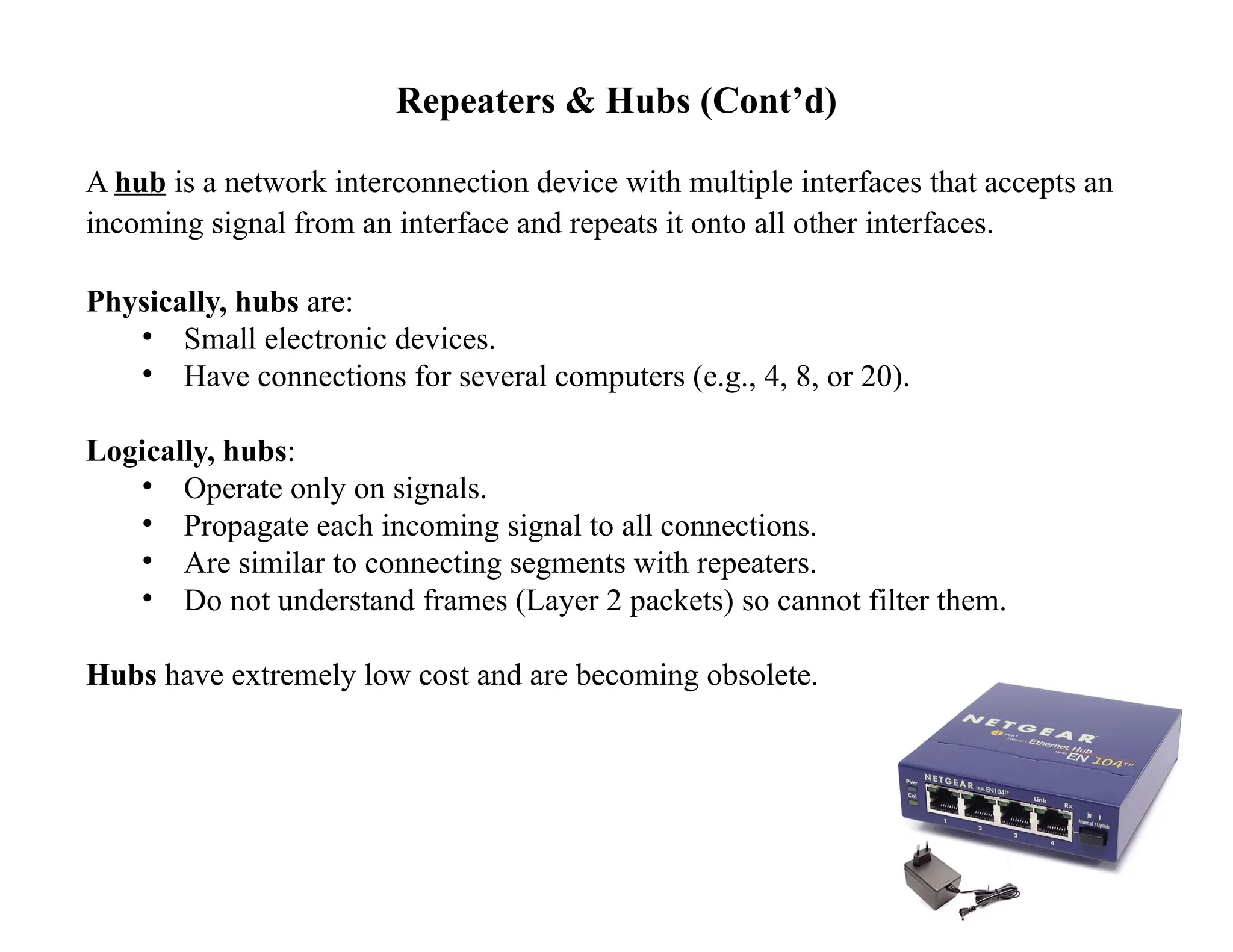
Repeaters & Hubs(Cont’d)
A hub is a network interconnection device with multiple interfaces that accepts an
incoming signal from an interface and repeats it onto all other interfaces.
Physically, hubs are:
• Small electronic devices.
• Have connections for several computers (e.g., 4, 8, or 20).
Logically, hubs:
• Operate only on signals.
• Propagate each incoming signal to all connections.
• Are similar to connecting segments with repeaters.
• Do not understand frames (Layer 2 packets) so cannot filter them.
Hubs have extremely low cost and are becoming obsolete.
5.
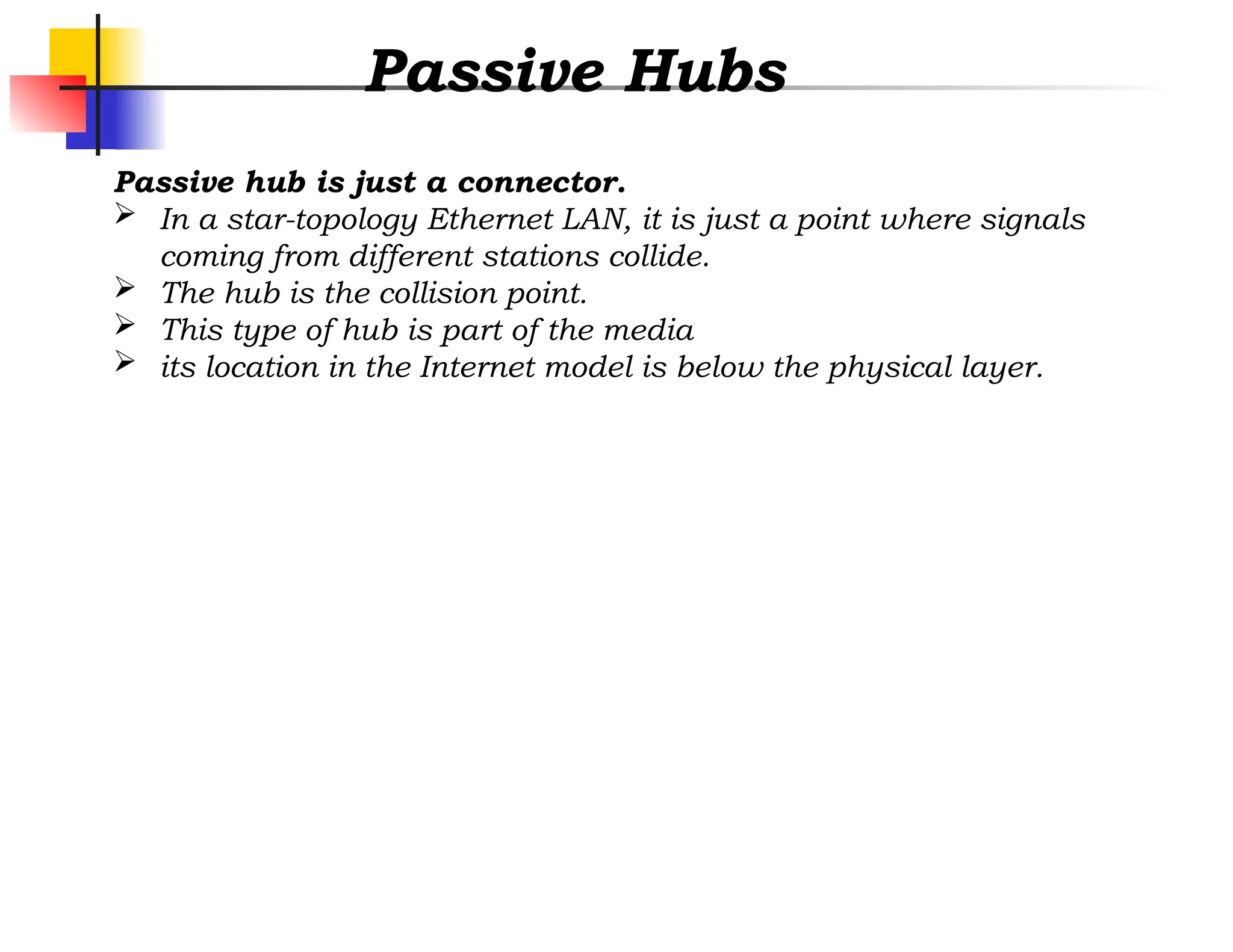
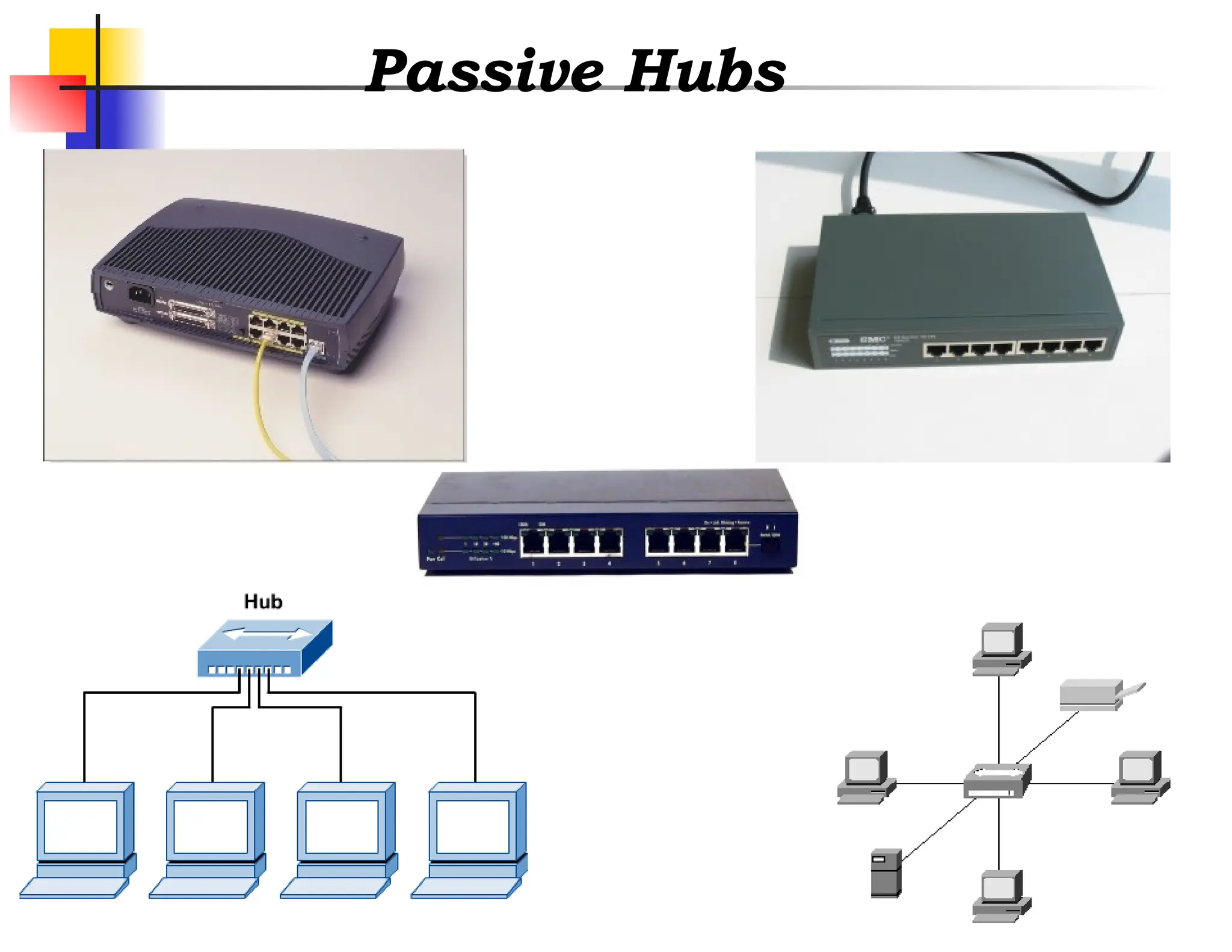
Passive Hubs
Passive hubis just a connector.
In a star-topology Ethernet LAN, it is just a point where signals
coming from different stations collide.
The hub is the collision point.
This type of hub is part of the media
its location in the Internet model is below the physical layer.
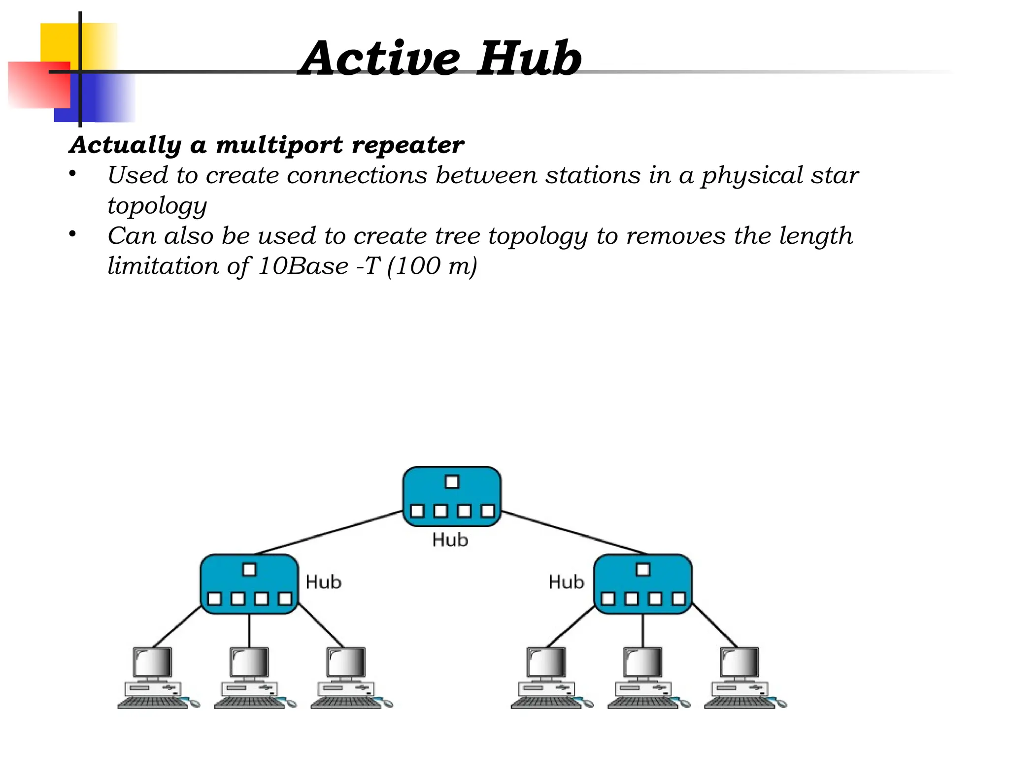
Active Hub
Actually amultiport repeater
• Used to create connections between stations in a physical star
topology
• Can also be used to create tree topology to removes the length
limitation of 10Base -T (100 m)
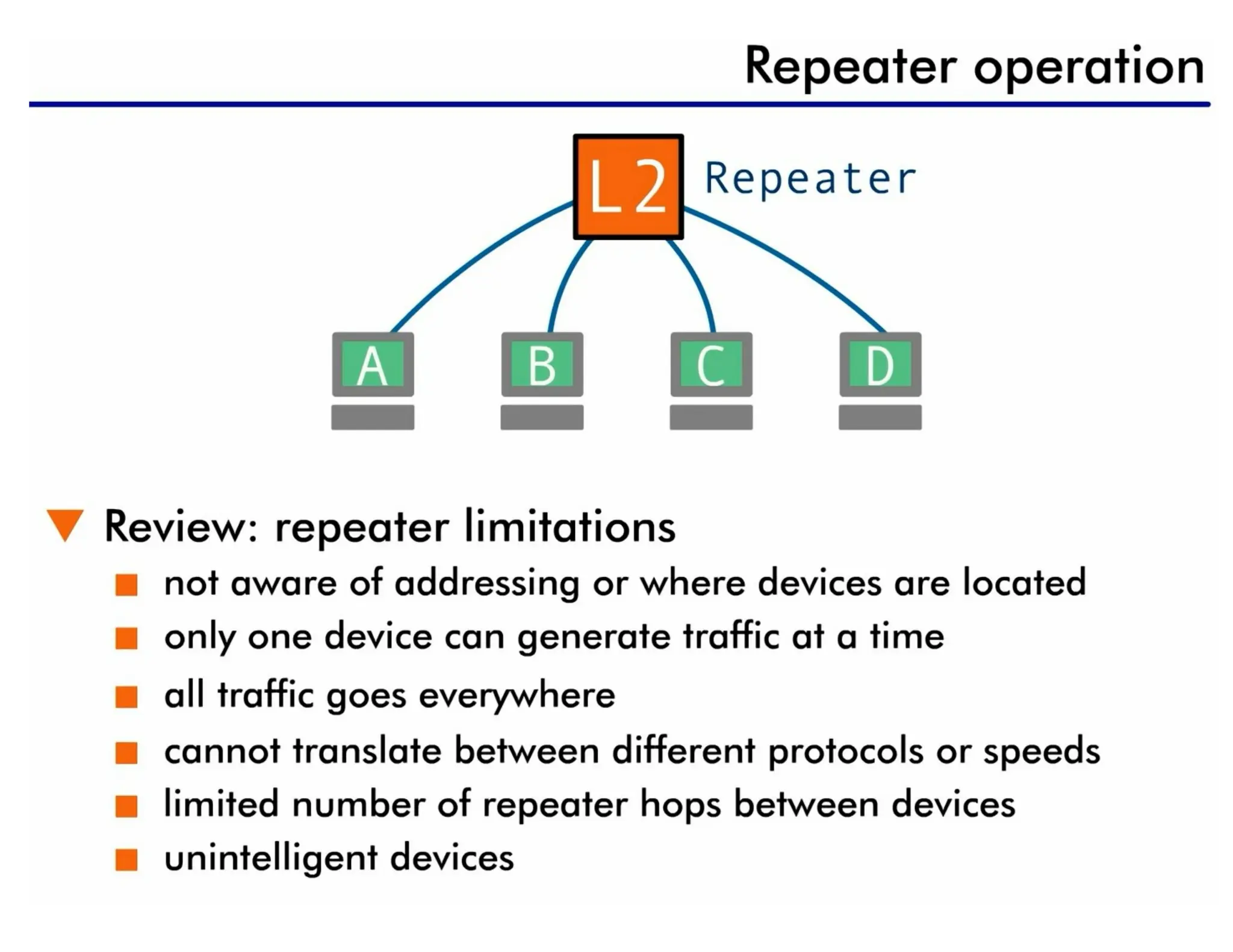
repeater
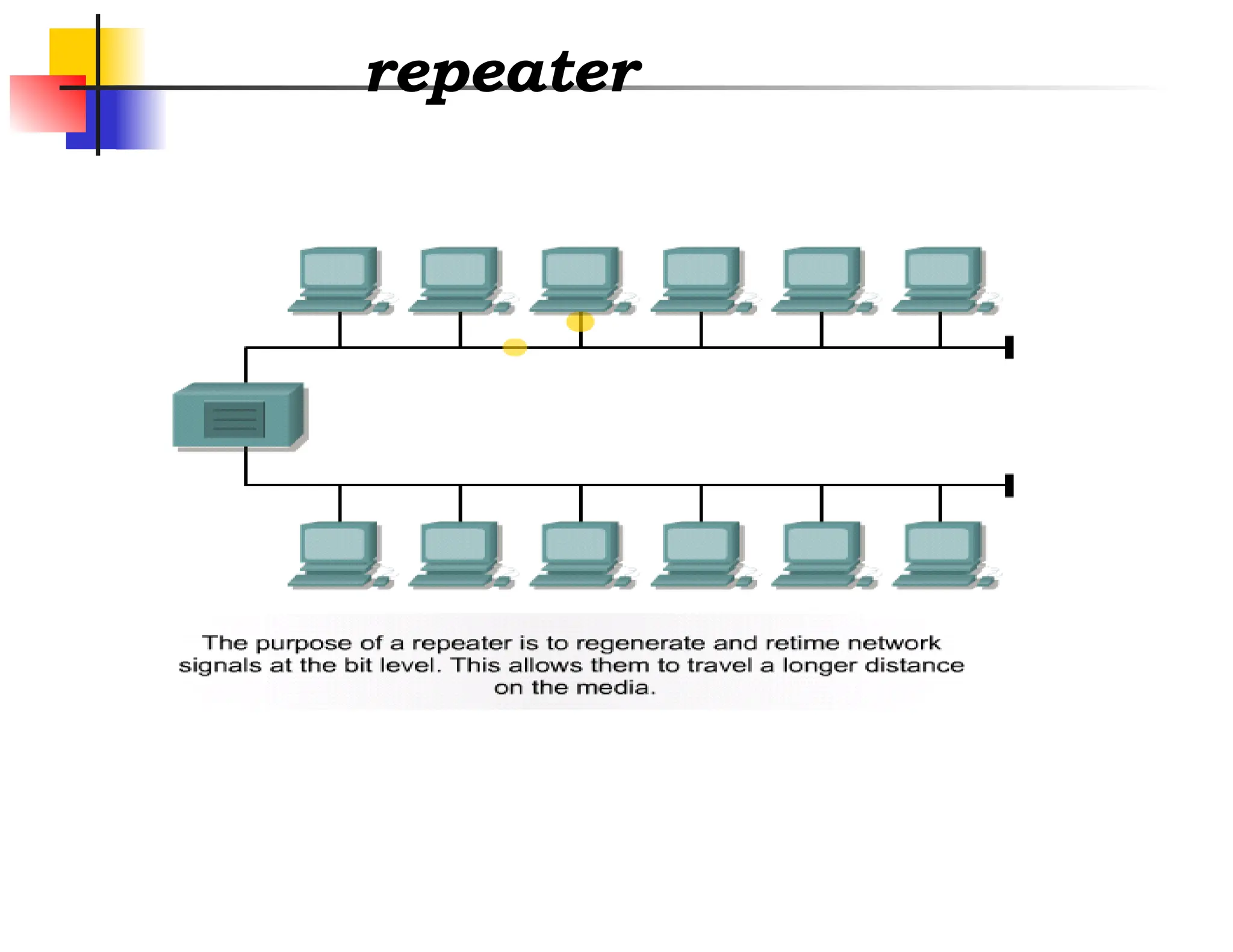
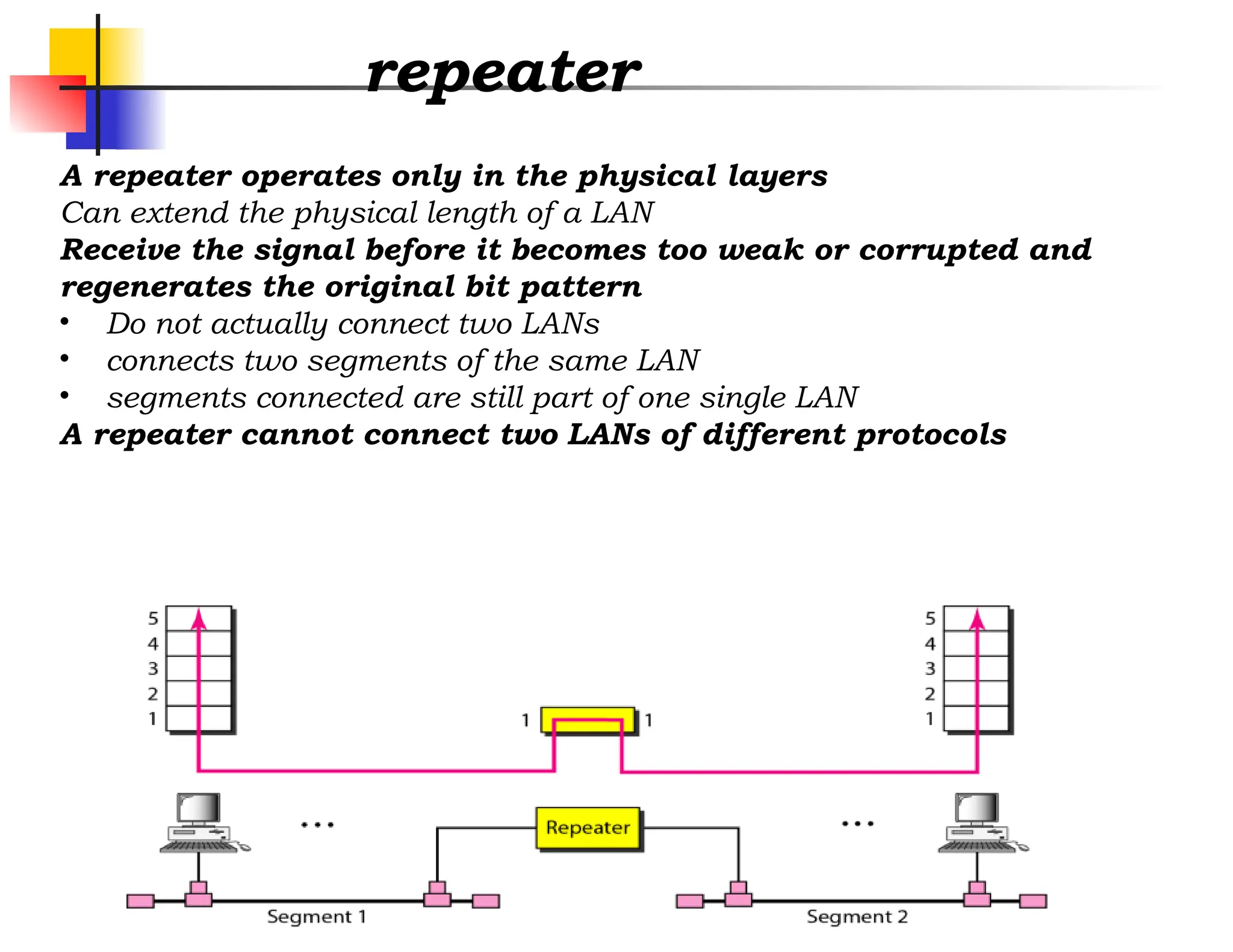
A repeater operatesonly in the physical layers
Can extend the physical length of a LAN
Receive the signal before it becomes too weak or corrupted and
regenerates the original bit pattern
• Do not actually connect two LANs
• connects two segments of the same LAN
• segments connected are still part of one single LAN
A repeater cannot connect two LANs of different protocols
10.
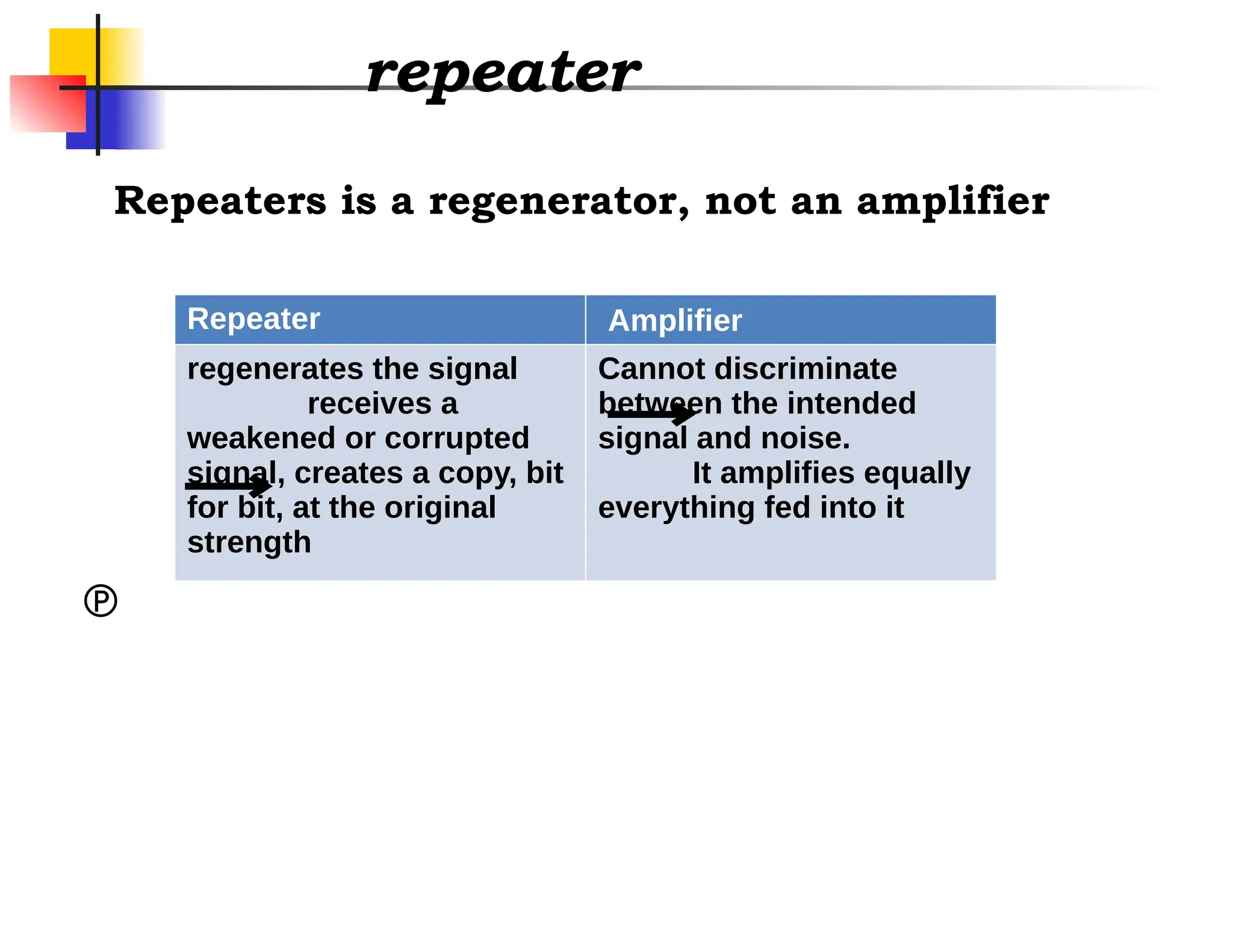
repeater
Repeater Amplifier
regenerates thesignal
receives a
weakened or corrupted
signal, creates a copy, bit
for bit, at the original
strength
Cannot discriminate
between the intended
signal and noise.
It amplifies equally
everything fed into it
Repeaters is a regenerator, not an amplifier
11.
10.
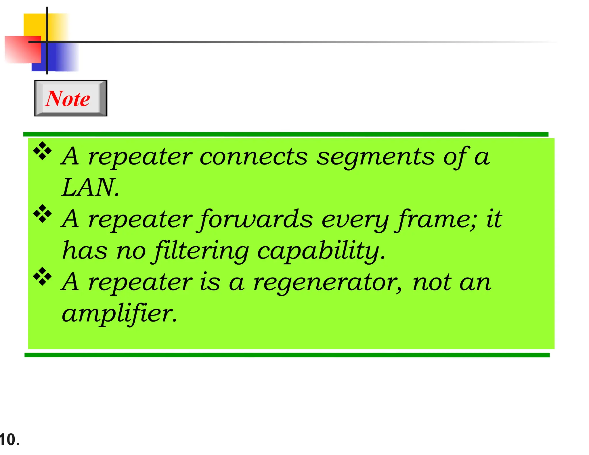
A repeaterconnects segments of a
LAN.
A repeater forwards every frame; it
has no filtering capability.
A repeater is a regenerator, not an
amplifier.
Note
12.
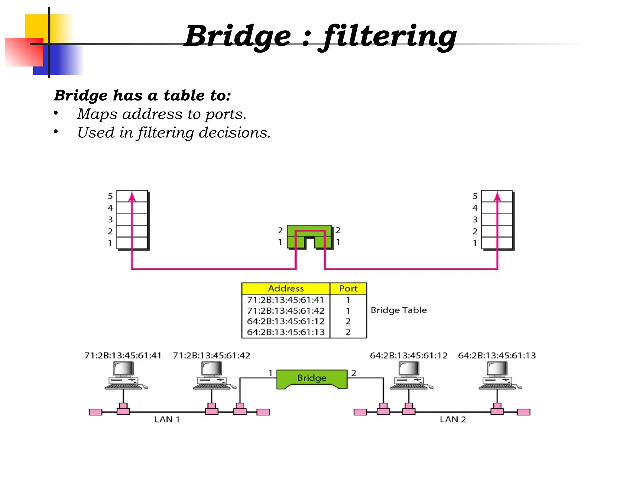
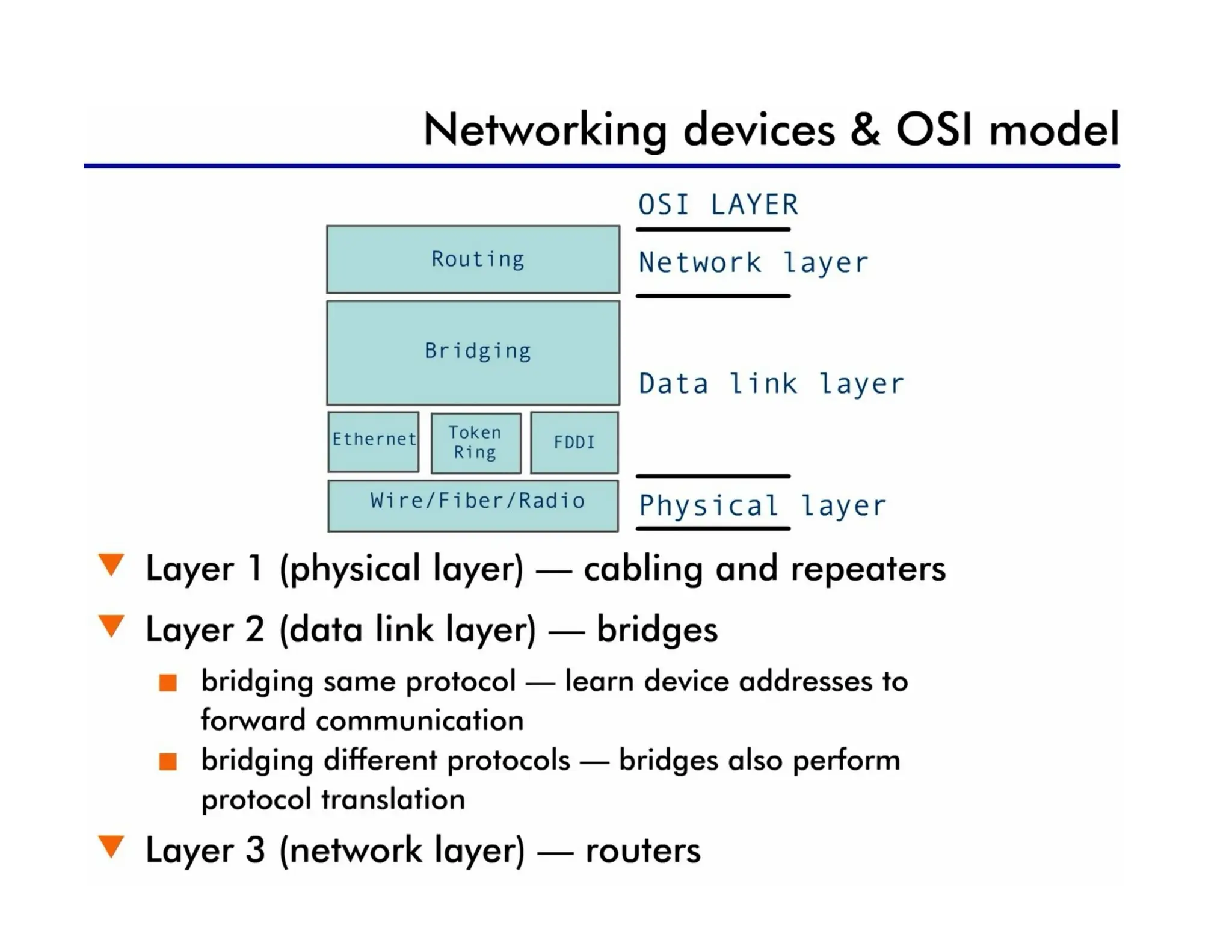
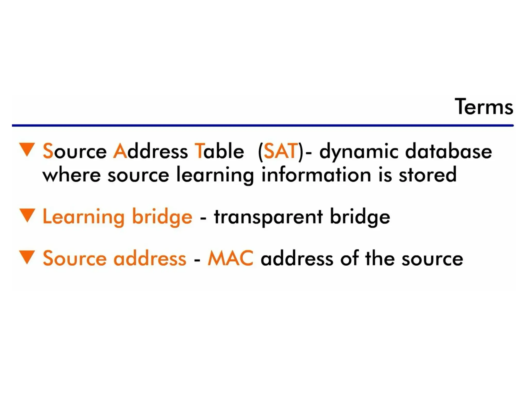
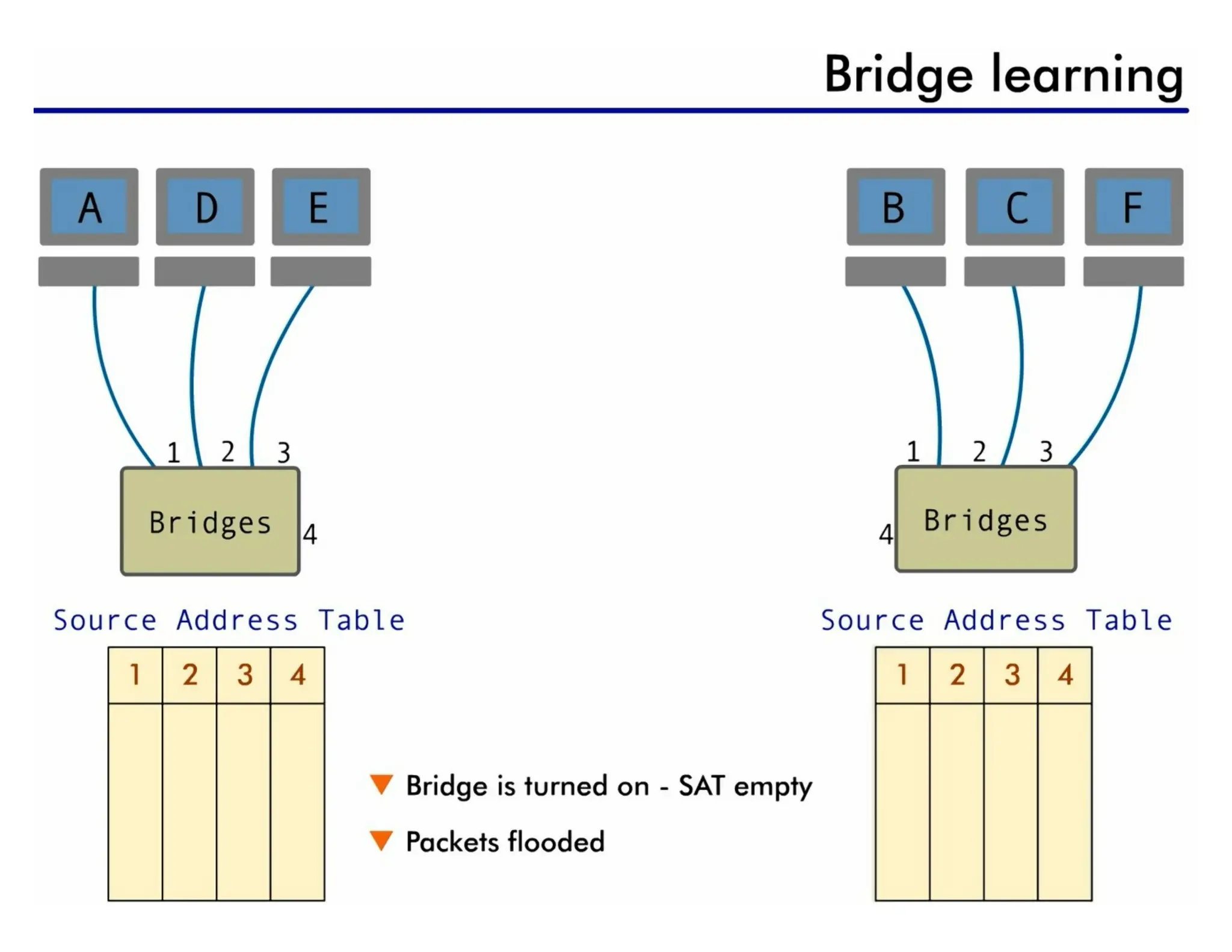
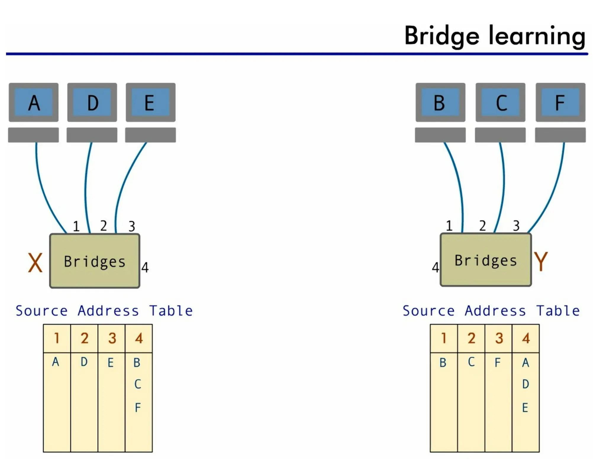
Bridge
Operates in boththe physical and the data link layer
• physical layer : regenerates the signal
• data link layer : check the physical (MAC) addresses (source and
destination) contained in the frame
Bridge has filtering capability, but repeaters has not.
• checks the MAC (physical) address of the destination when receives a
frame, and decide if the frame should be forwarded or dropped
• forwards the new copy only to the segment (specific port) to which the
address belongs
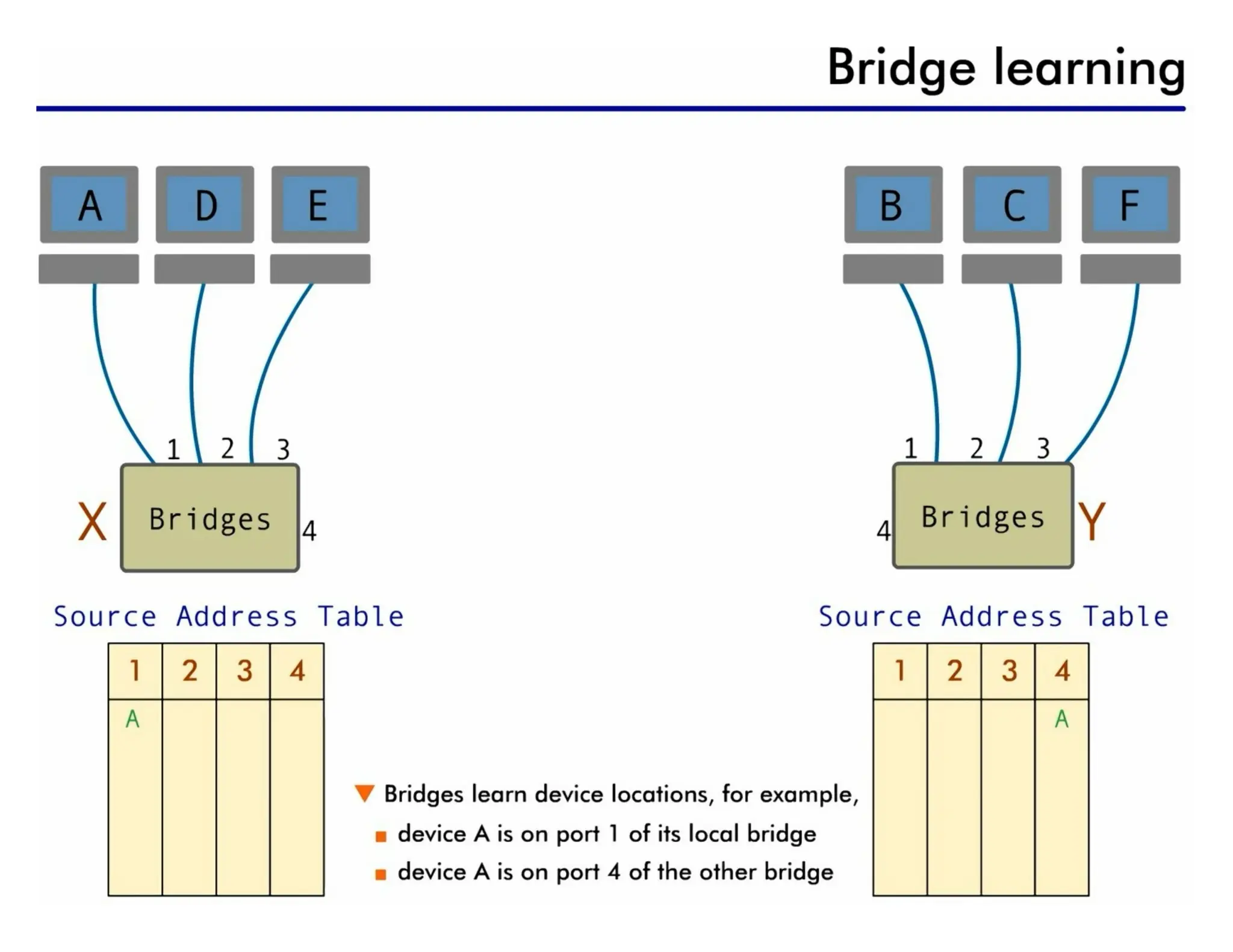
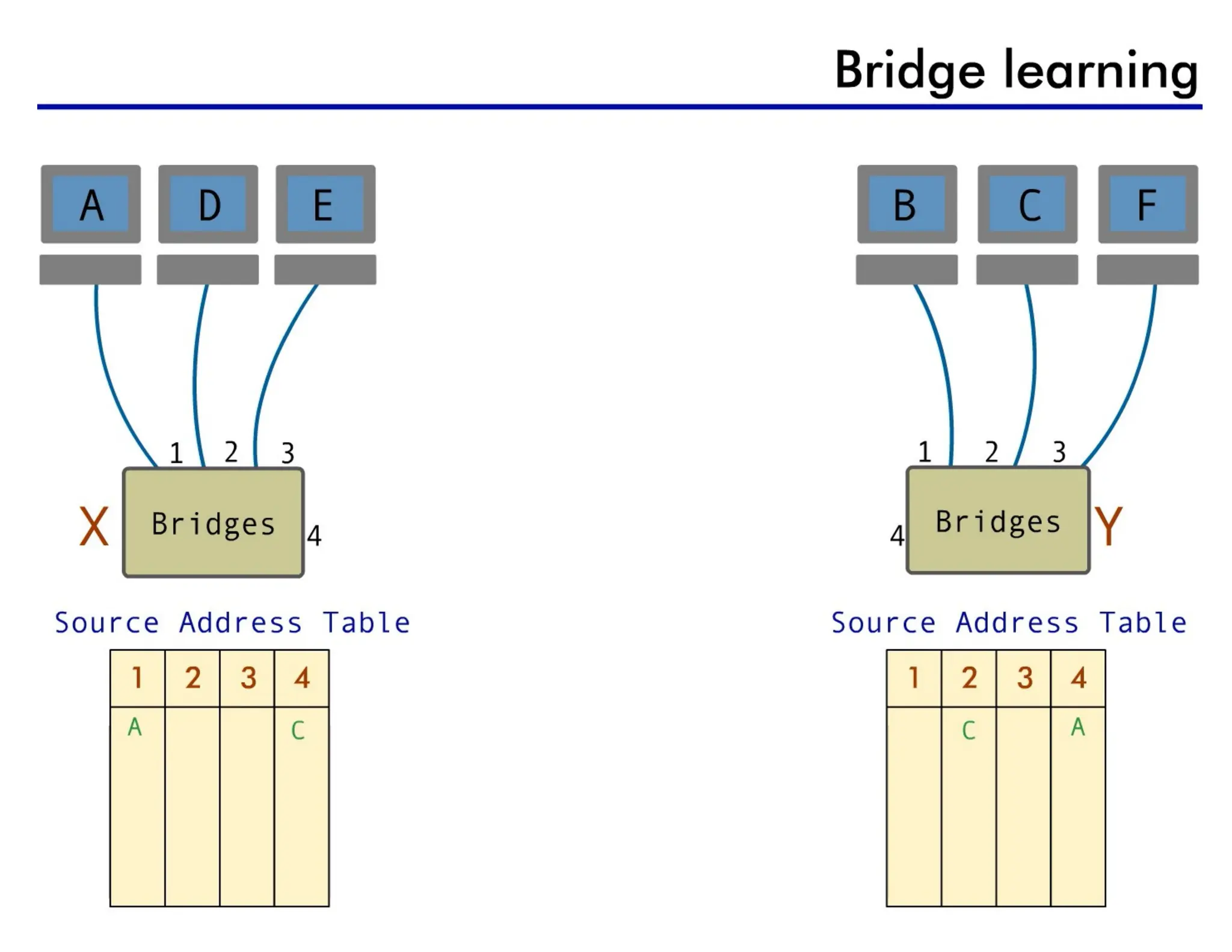
• bridge has a table that maps addresses to the port.
Two-Layer Switch
Performs atthe physical and data link layers.
• Is a bridge with many ports (multi port bridge) Design that allows better
(faster) performance
• No collision
• Filtering based on the MAC address of the frame it received (like bridge)
• Builds switching table by “learning” MAC host addresses from source
addresses of incoming packets
• Unknown destination addresses are flooded out other ports
• Broadcast frames are flooded out other ports.
• have been designed to forward the frame as soon as they check the MAC
addresses in the header of the frame( first 6-bytes).
15.
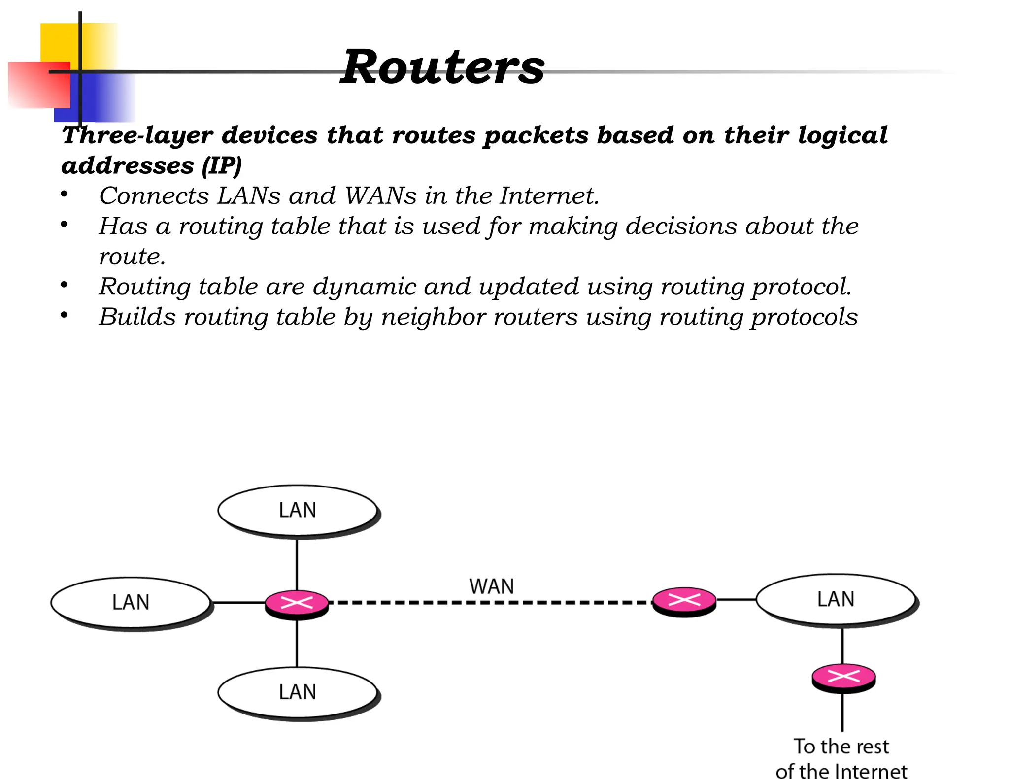
Routers
Three-layer devices thatroutes packets based on their logical
addresses (IP)
• Connects LANs and WANs in the Internet.
• Has a routing table that is used for making decisions about the
route.
• Routing table are dynamic and updated using routing protocol.
• Builds routing table by neighbor routers using routing protocols
16.
Three layer switch
Isa router, but a faster and more
sophisticated.
•The switching fabric in a three-layer switch
allows faster table lookup and forwarding.
•We can use the terms router and three-layer
switch interchangeably.
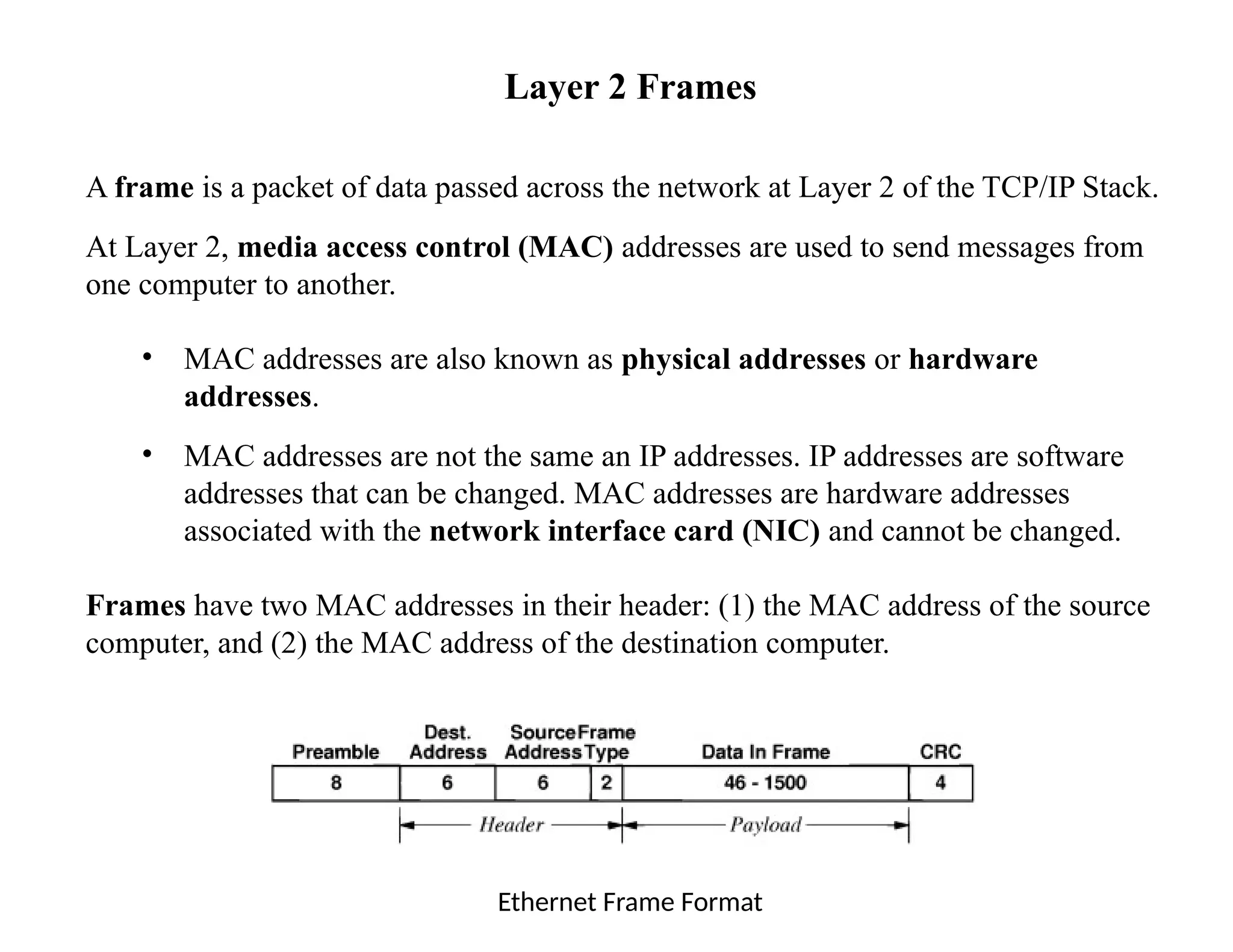
Layer 2 Frames
Aframe is a packet of data passed across the network at Layer 2 of the TCP/IP Stack.
At Layer 2, media access control (MAC) addresses are used to send messages from
one computer to another.
• MAC addresses are also known as physical addresses or hardware
addresses.
• MAC addresses are not the same an IP addresses. IP addresses are software
addresses that can be changed. MAC addresses are hardware addresses
associated with the network interface card (NIC) and cannot be changed.
Frames have two MAC addresses in their header: (1) the MAC address of the source
computer, and (2) the MAC address of the destination computer.
Ethernet Frame Format
19.
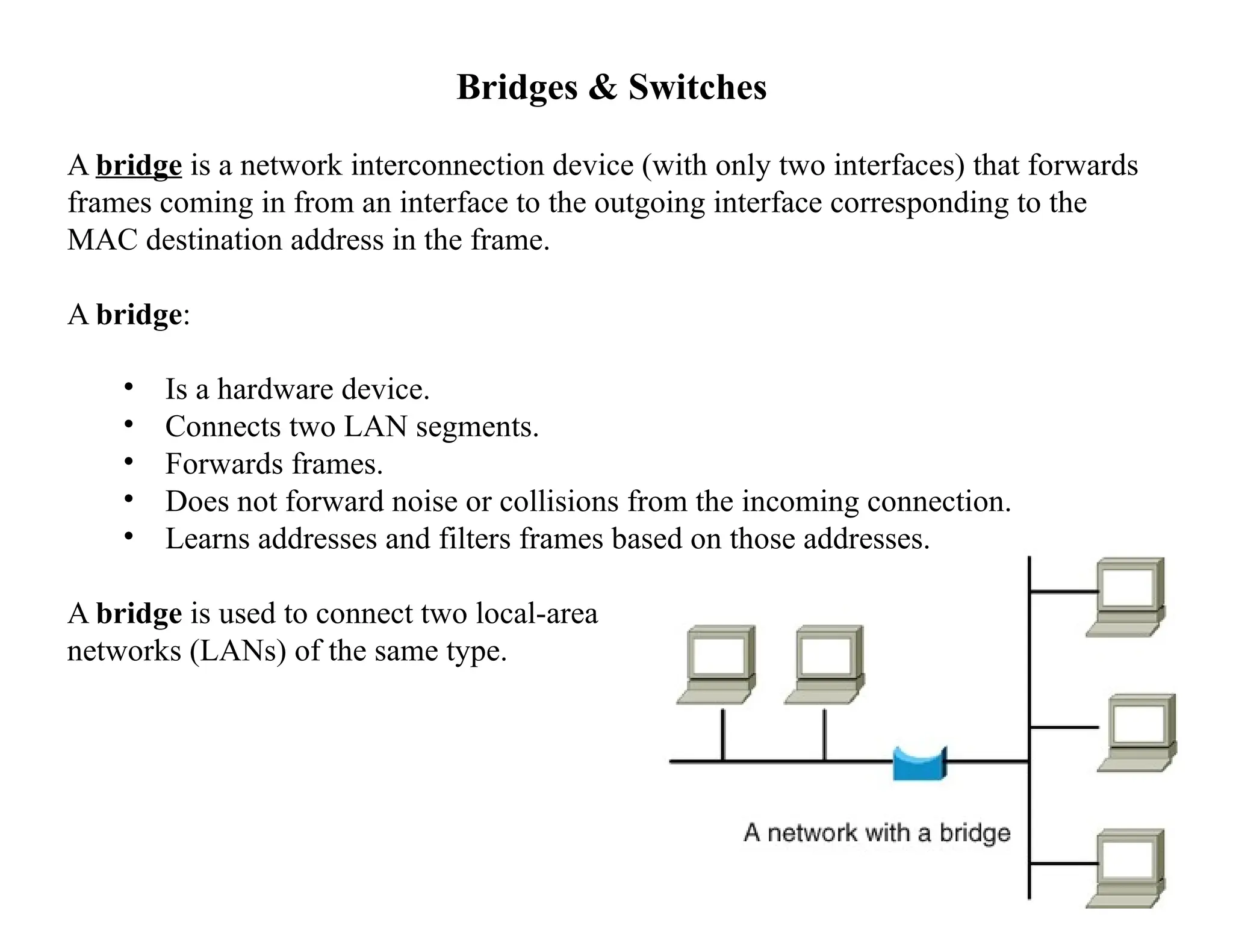
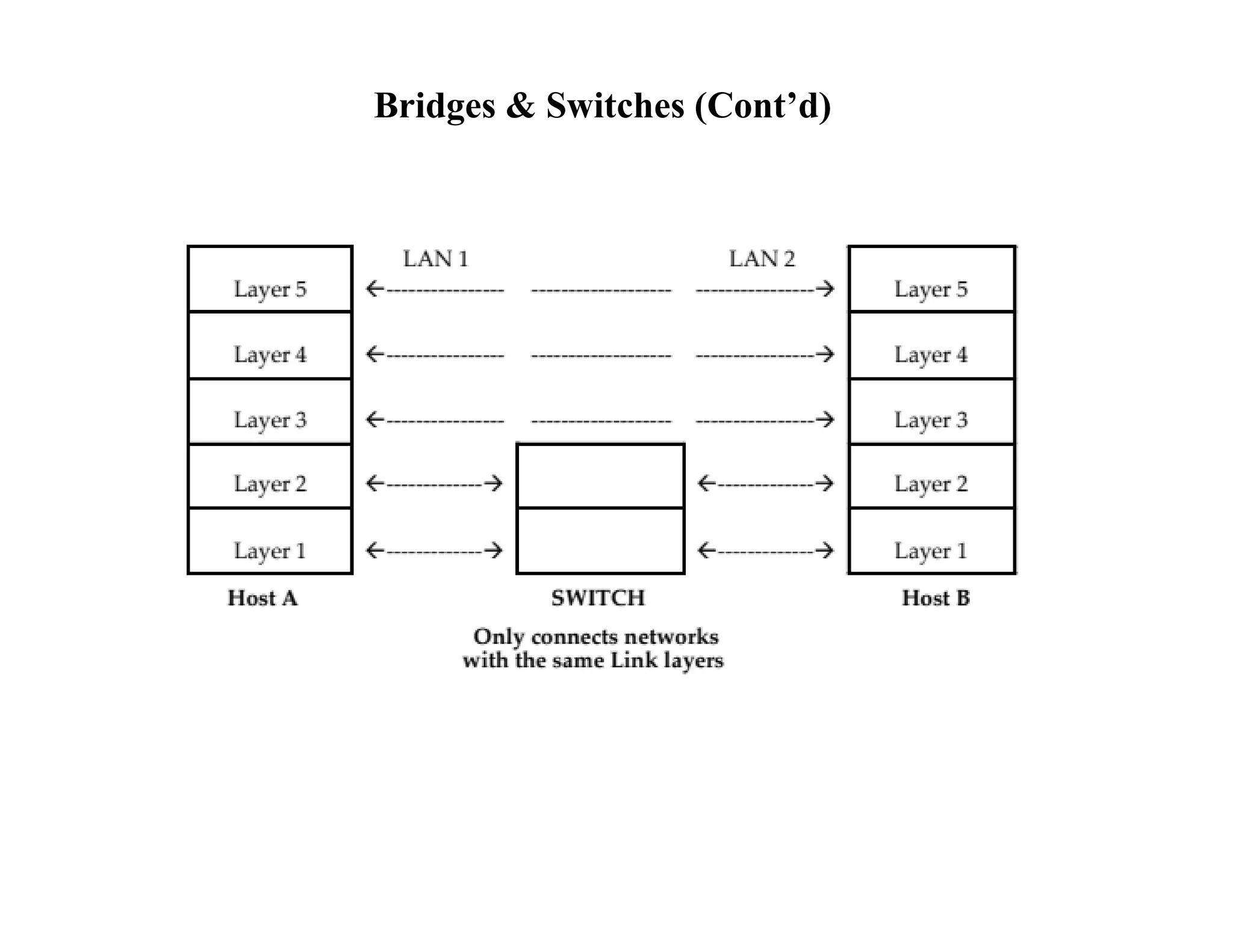
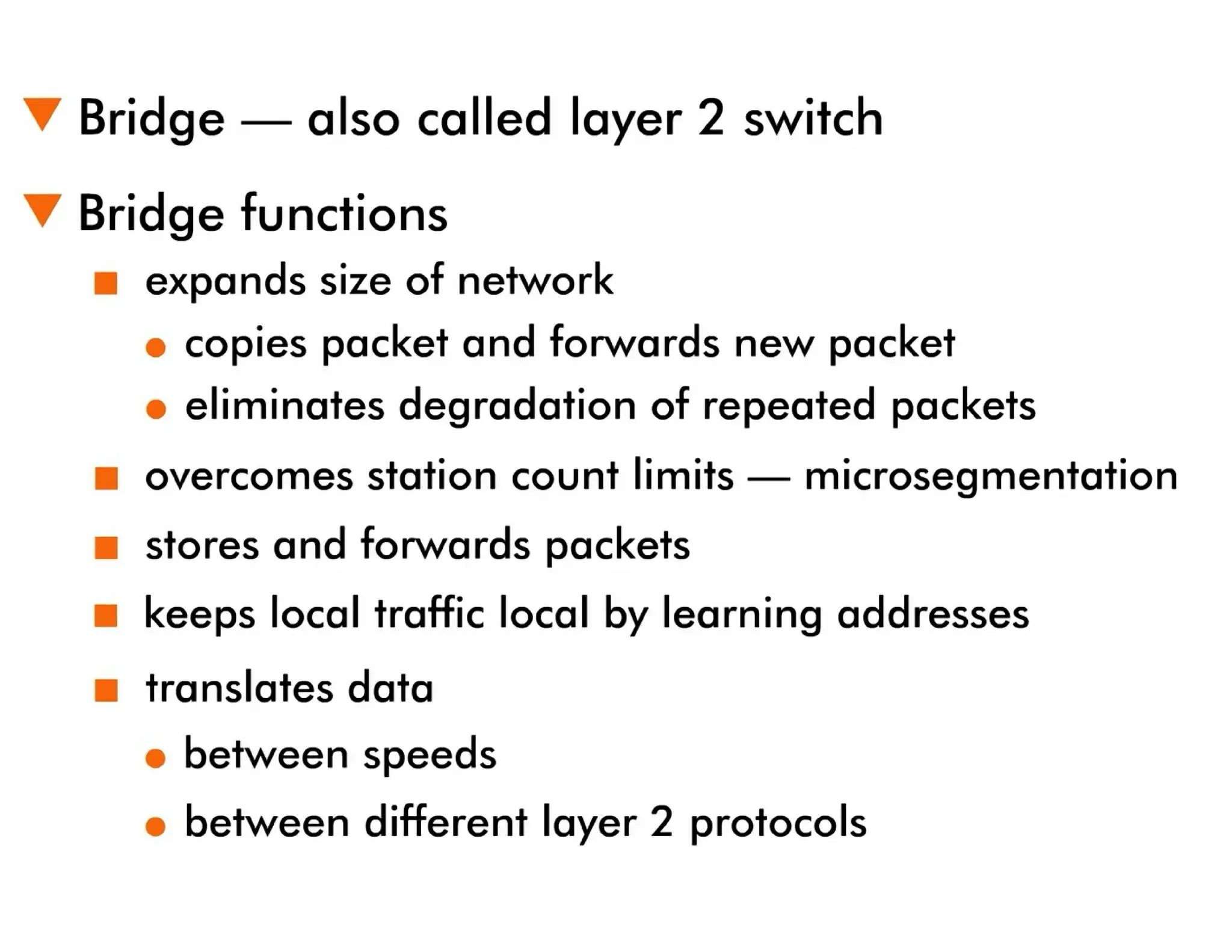
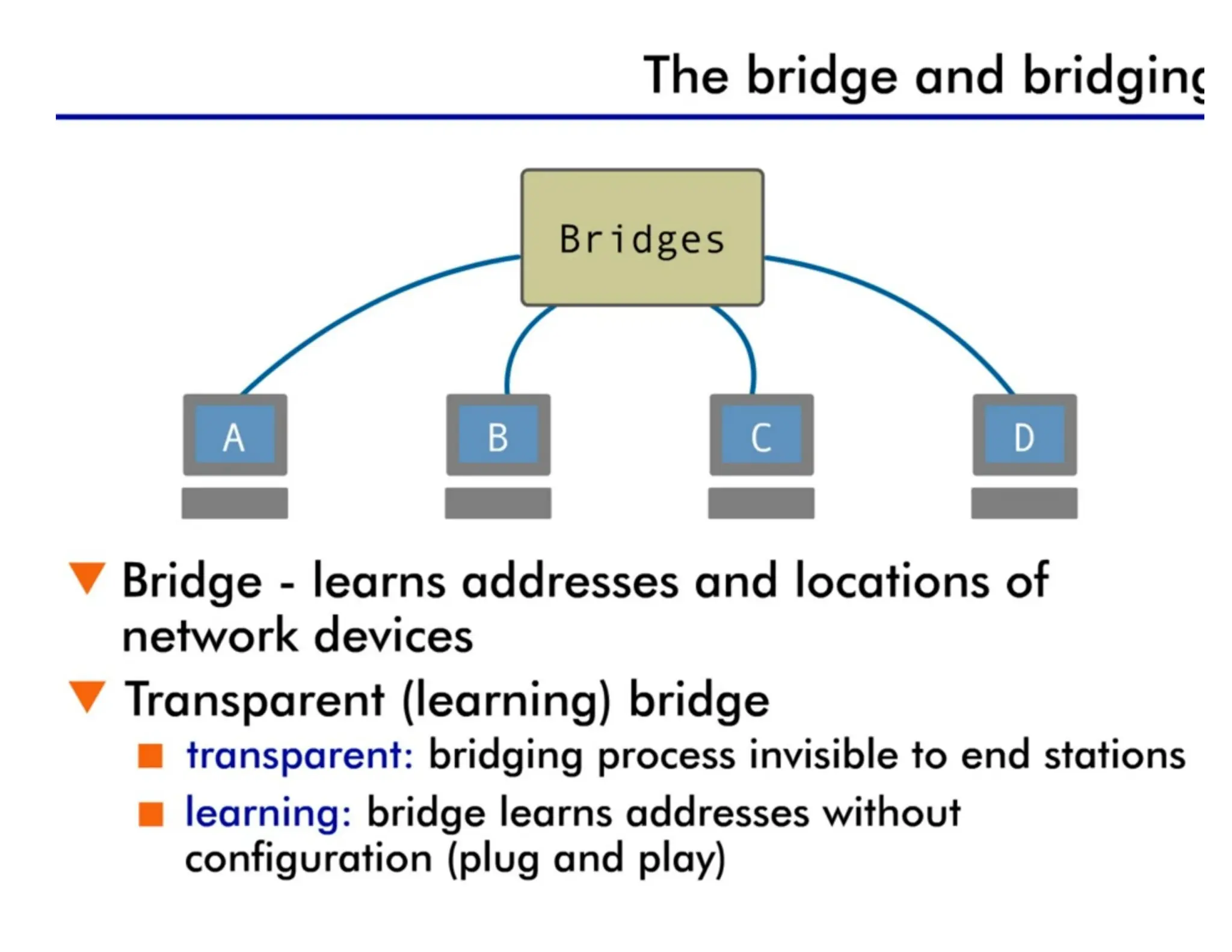
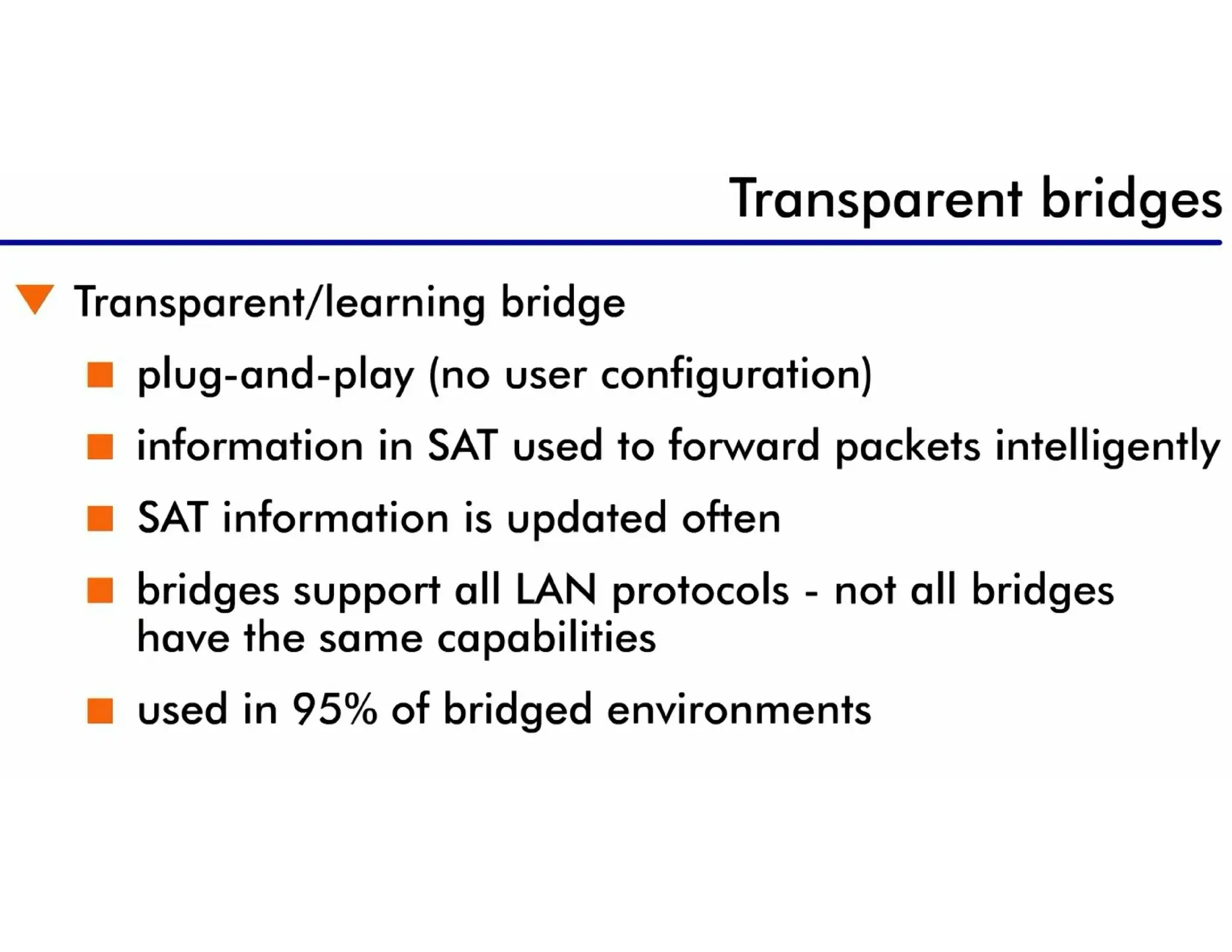
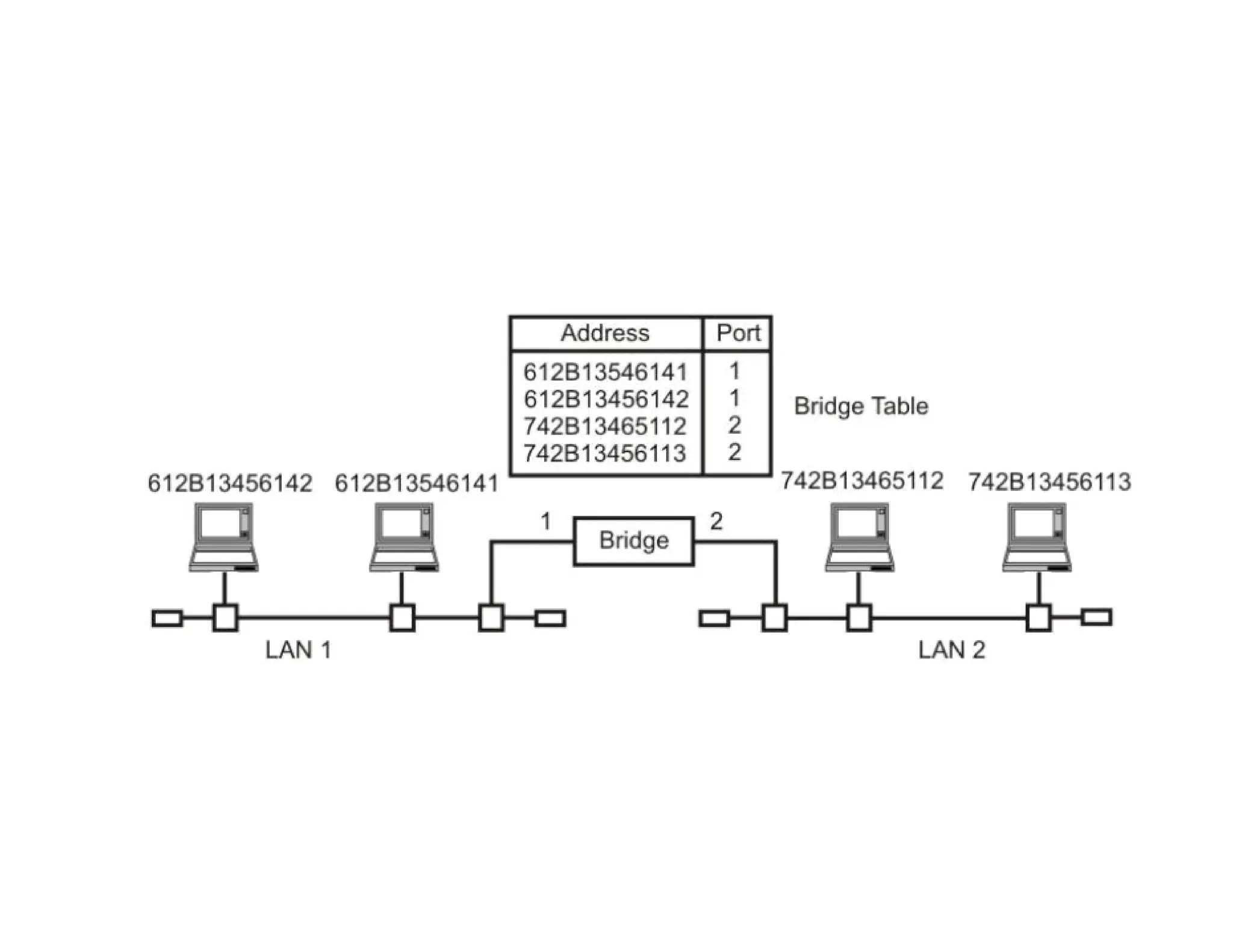
Bridges & Switches
Abridge is a network interconnection device (with only two interfaces) that forwards
frames coming in from an interface to the outgoing interface corresponding to the
MAC destination address in the frame.
A bridge:
• Is a hardware device.
• Connects two LAN segments.
• Forwards frames.
• Does not forward noise or collisions from the incoming connection.
• Learns addresses and filters frames based on those addresses.
A bridge is used to connect two local-area
networks (LANs) of the same type.
20.
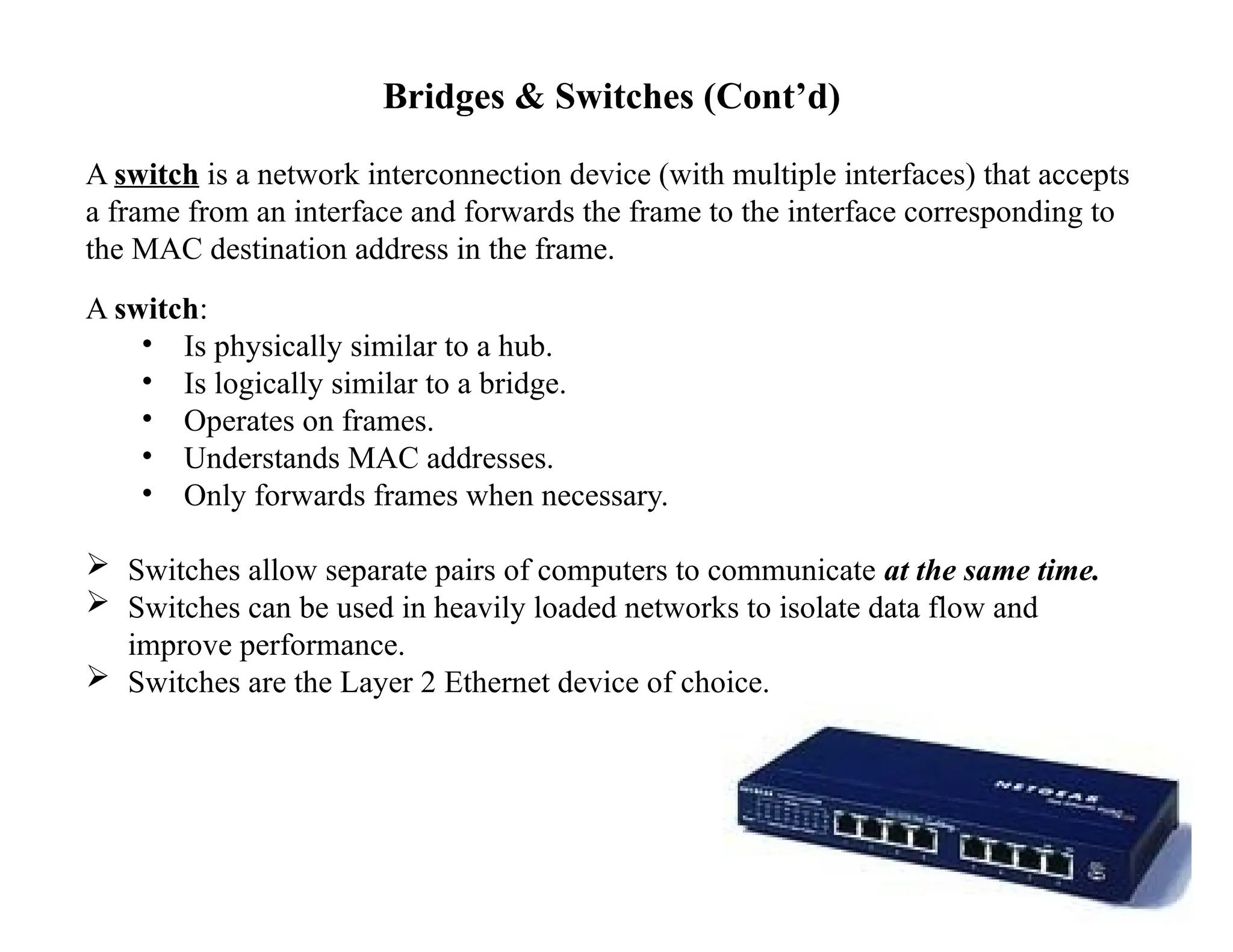
Bridges & Switches(Cont’d)
A switch is a network interconnection device (with multiple interfaces) that accepts
a frame from an interface and forwards the frame to the interface corresponding to
the MAC destination address in the frame.
A switch:
• Is physically similar to a hub.
• Is logically similar to a bridge.
• Operates on frames.
• Understands MAC addresses.
• Only forwards frames when necessary.
Switches allow separate pairs of computers to communicate at the same time.
Switches can be used in heavily loaded networks to isolate data flow and
improve performance.
Switches are the Layer 2 Ethernet device of choice.
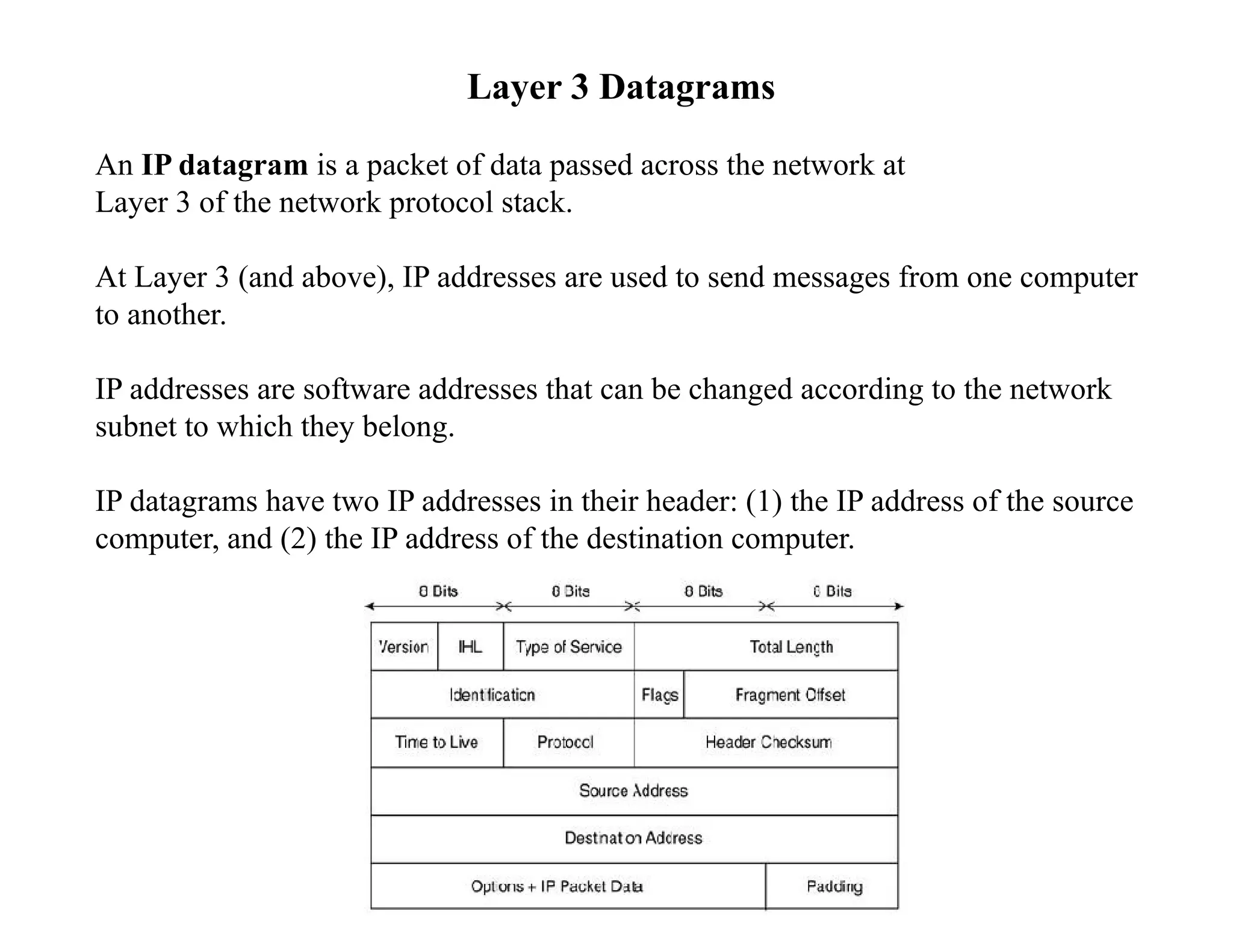
Layer 3 Datagrams
AnIP datagram is a packet of data passed across the network at
Layer 3 of the network protocol stack.
At Layer 3 (and above), IP addresses are used to send messages from one computer
to another.
IP addresses are software addresses that can be changed according to the network
subnet to which they belong.
IP datagrams have two IP addresses in their header: (1) the IP address of the source
computer, and (2) the IP address of the destination computer.
23.
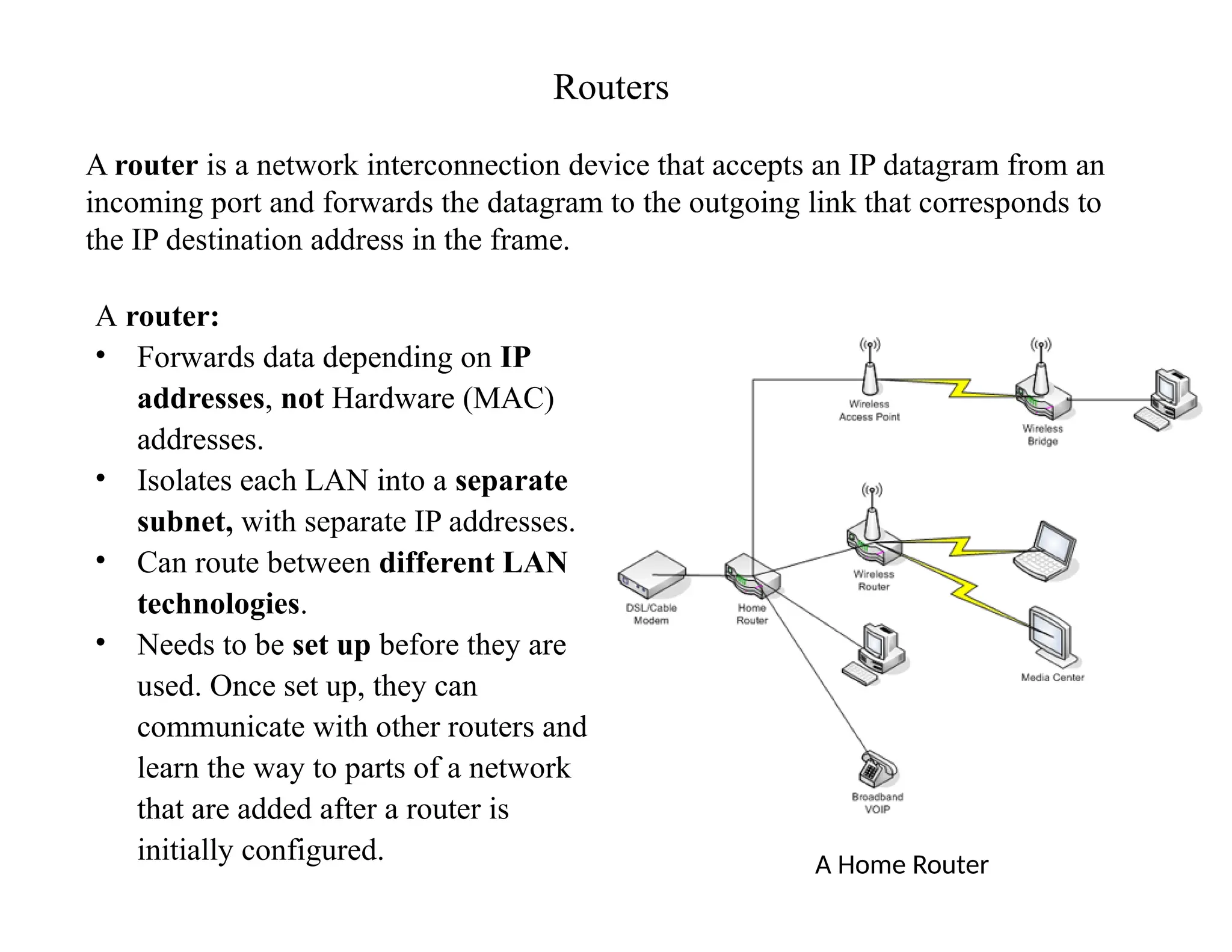
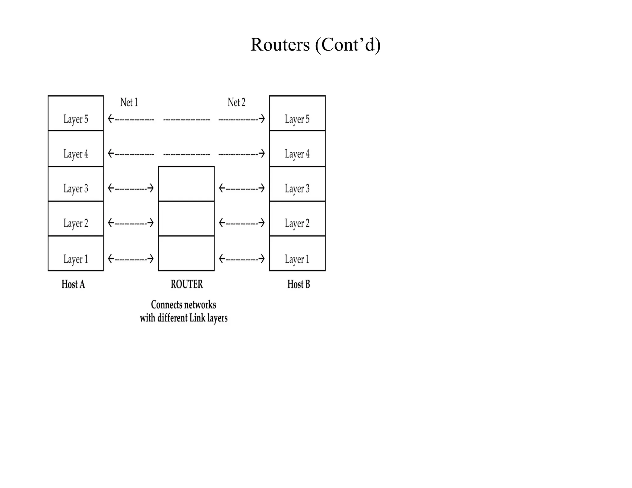
Routers
A router isa network interconnection device that accepts an IP datagram from an
incoming port and forwards the datagram to the outgoing link that corresponds to
the IP destination address in the frame.
A router:
• Forwards data depending on IP
addresses, not Hardware (MAC)
addresses.
• Isolates each LAN into a separate
subnet, with separate IP addresses.
• Can route between different LAN
technologies.
• Needs to be set up before they are
used. Once set up, they can
communicate with other routers and
learn the way to parts of a network
that are added after a router is
initially configured. A Home Router
FORWARDING APPROACHES
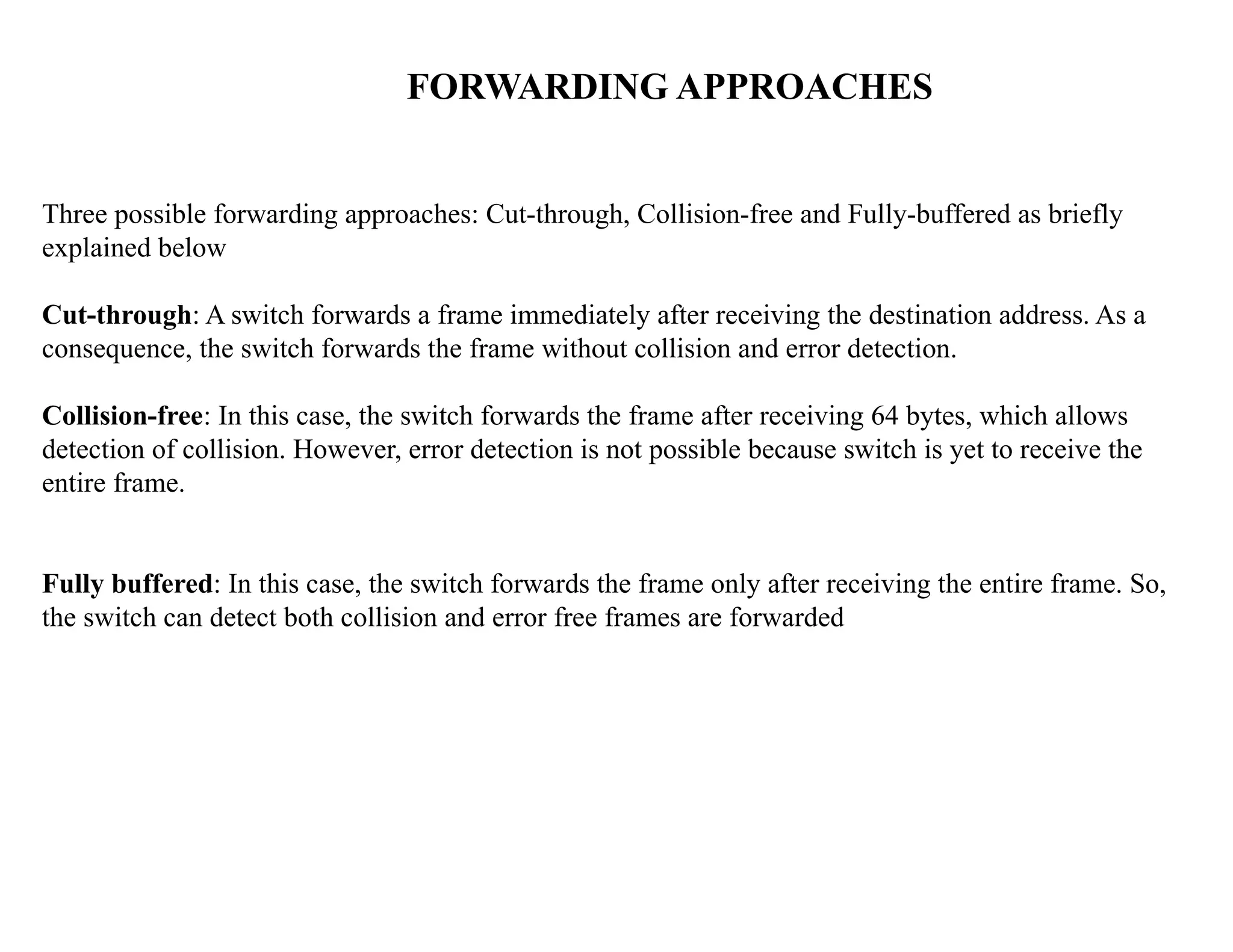
Three possibleforwarding approaches: Cut-through, Collision-free and Fully-buffered as briefly
explained below
Cut-through: A switch forwards a frame immediately after receiving the destination address. As a
consequence, the switch forwards the frame without collision and error detection.
Collision-free: In this case, the switch forwards the frame after receiving 64 bytes, which allows
detection of collision. However, error detection is not possible because switch is yet to receive the
entire frame.
Fully buffered: In this case, the switch forwards the frame only after receiving the entire frame. So,
the switch can detect both collision and error free frames are forwarded
46.
46
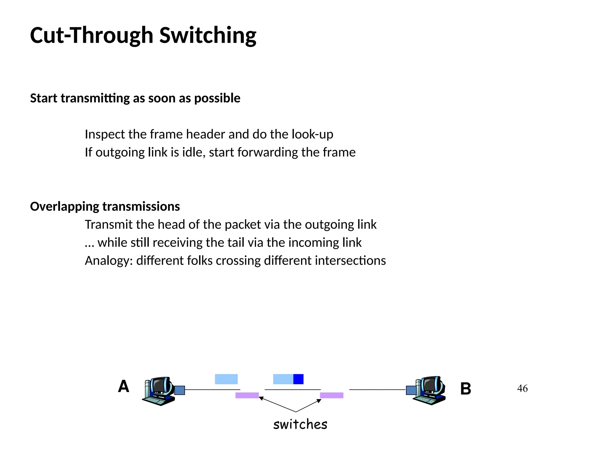
Cut-Through Switching
Start transmittingas soon as possible
Inspect the frame header and do the look-up
If outgoing link is idle, start forwarding the frame
Overlapping transmissions
Transmit the head of the packet via the outgoing link
… while still receiving the tail via the incoming link
Analogy: different folks crossing different intersections
A B
switches
47.
47
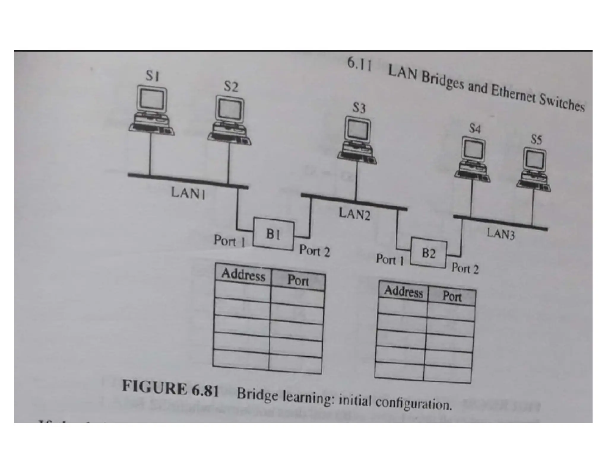
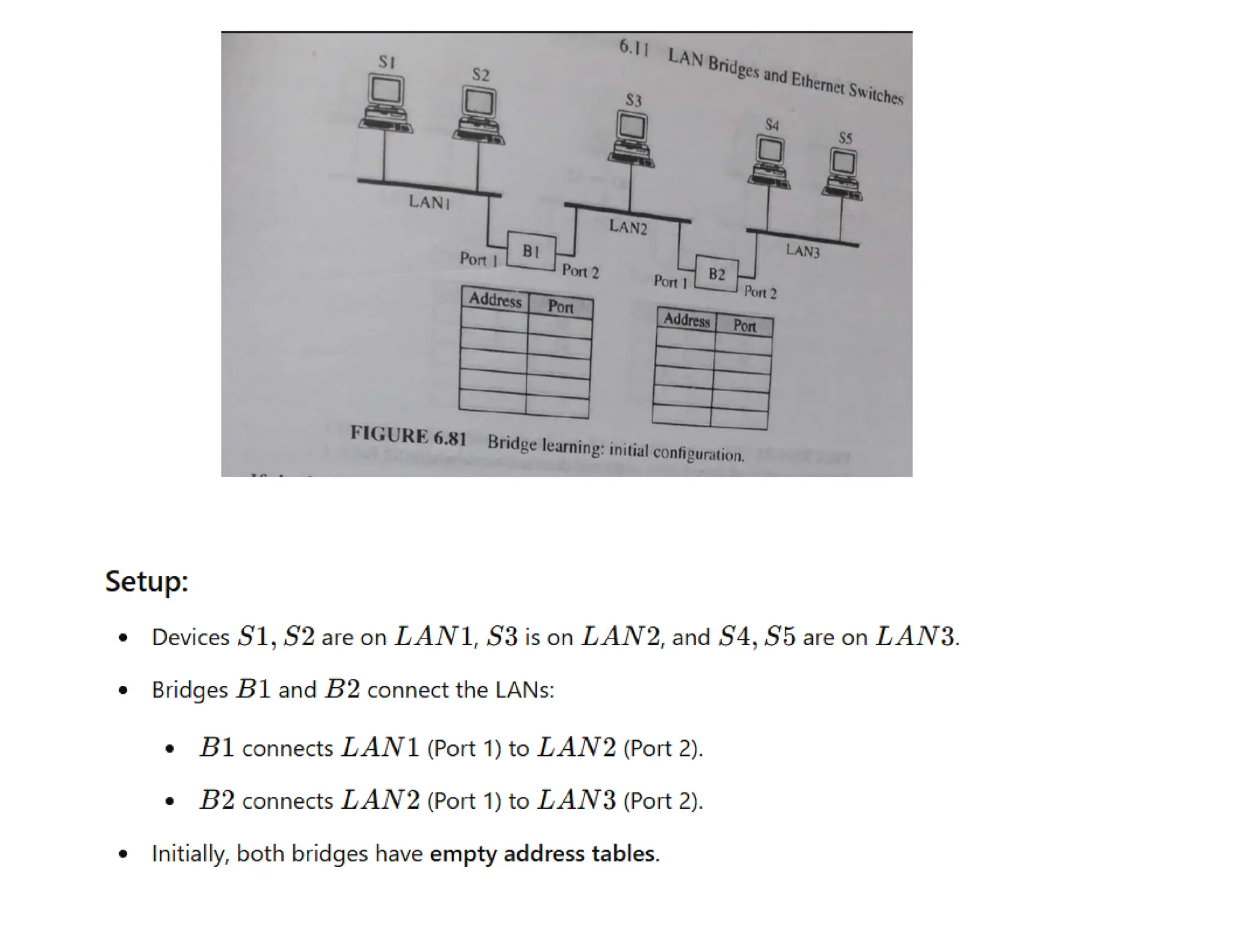
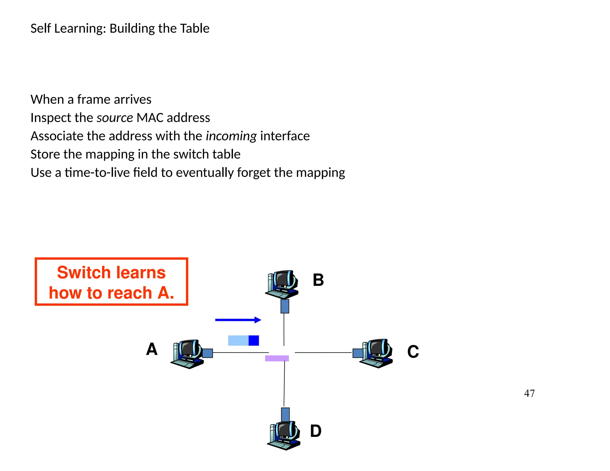
Self Learning: Buildingthe Table
When a frame arrives
Inspect the source MAC address
Associate the address with the incoming interface
Store the mapping in the switch table
Use a time-to-live field to eventually forget the mapping
A
B
C
D
Switch learns
how to reach A.
48.
48
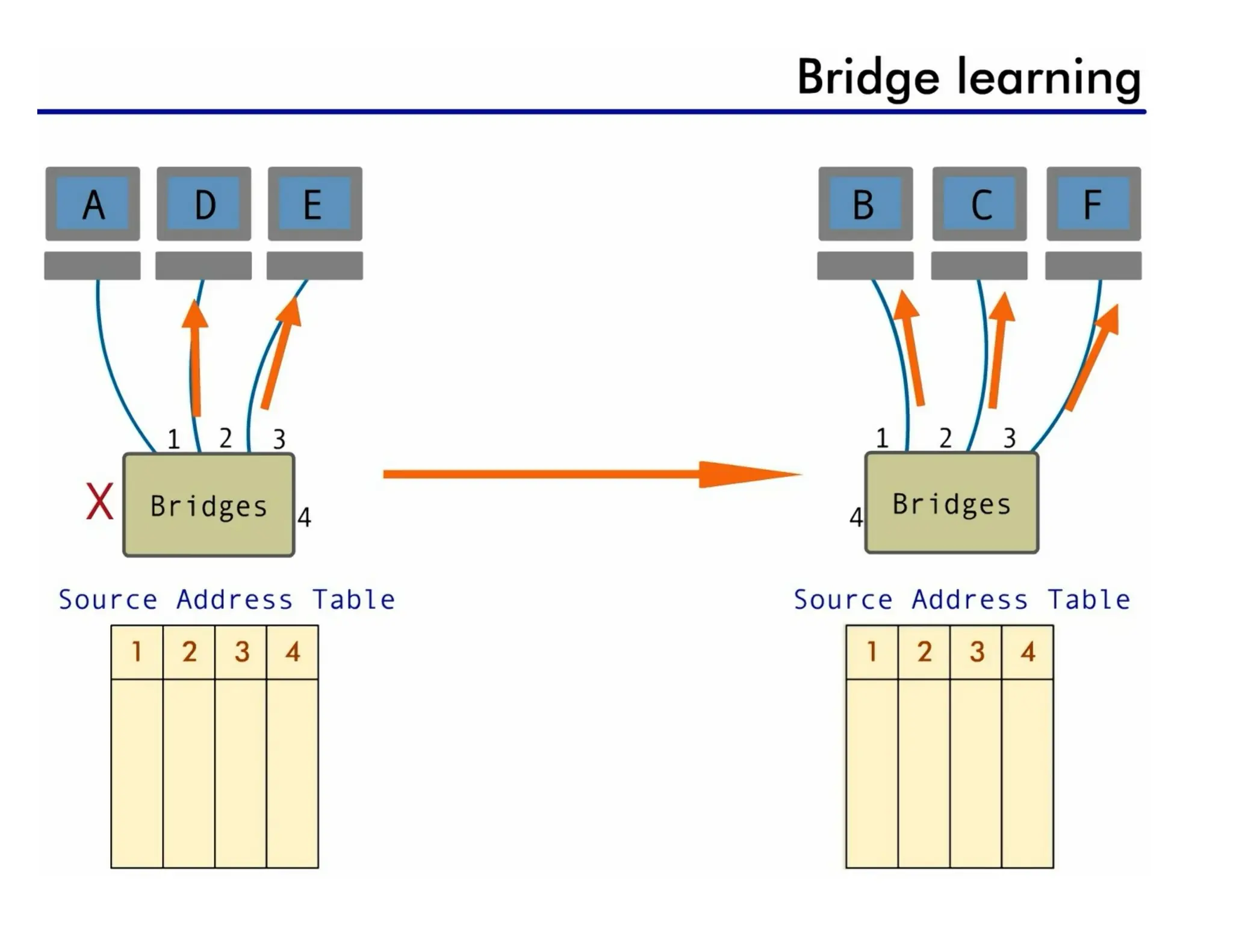
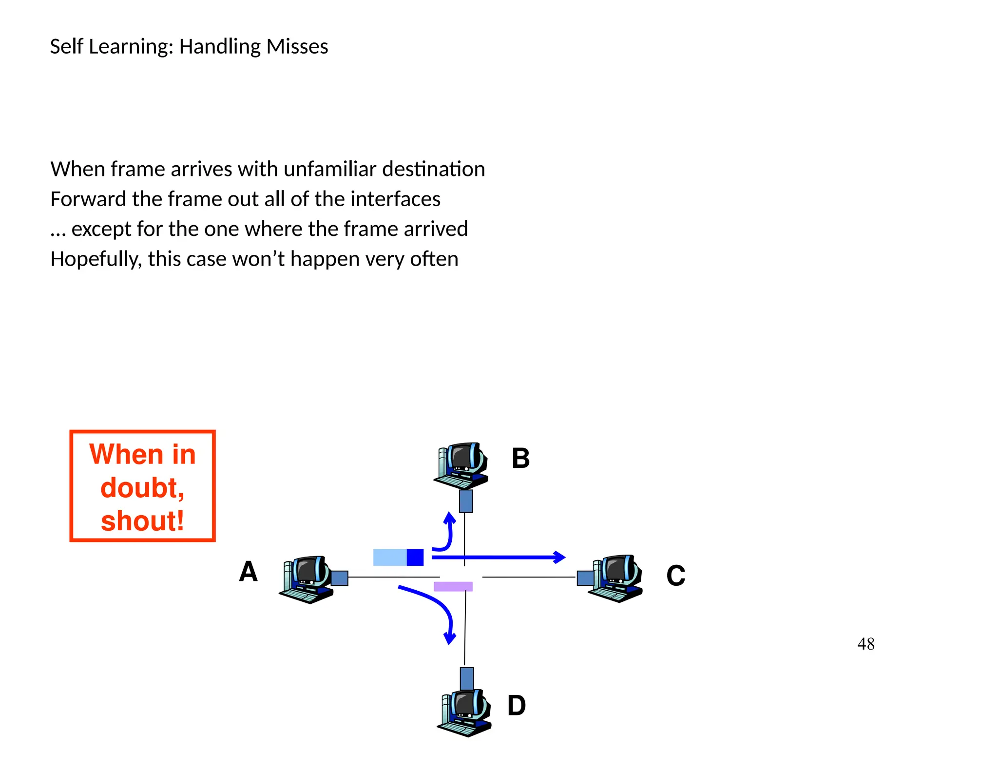
Self Learning: HandlingMisses
When frame arrives with unfamiliar destination
Forward the frame out all of the interfaces
… except for the one where the frame arrived
Hopefully, this case won’t happen very often
A
B
C
D
When in
doubt,
shout!
49.
49
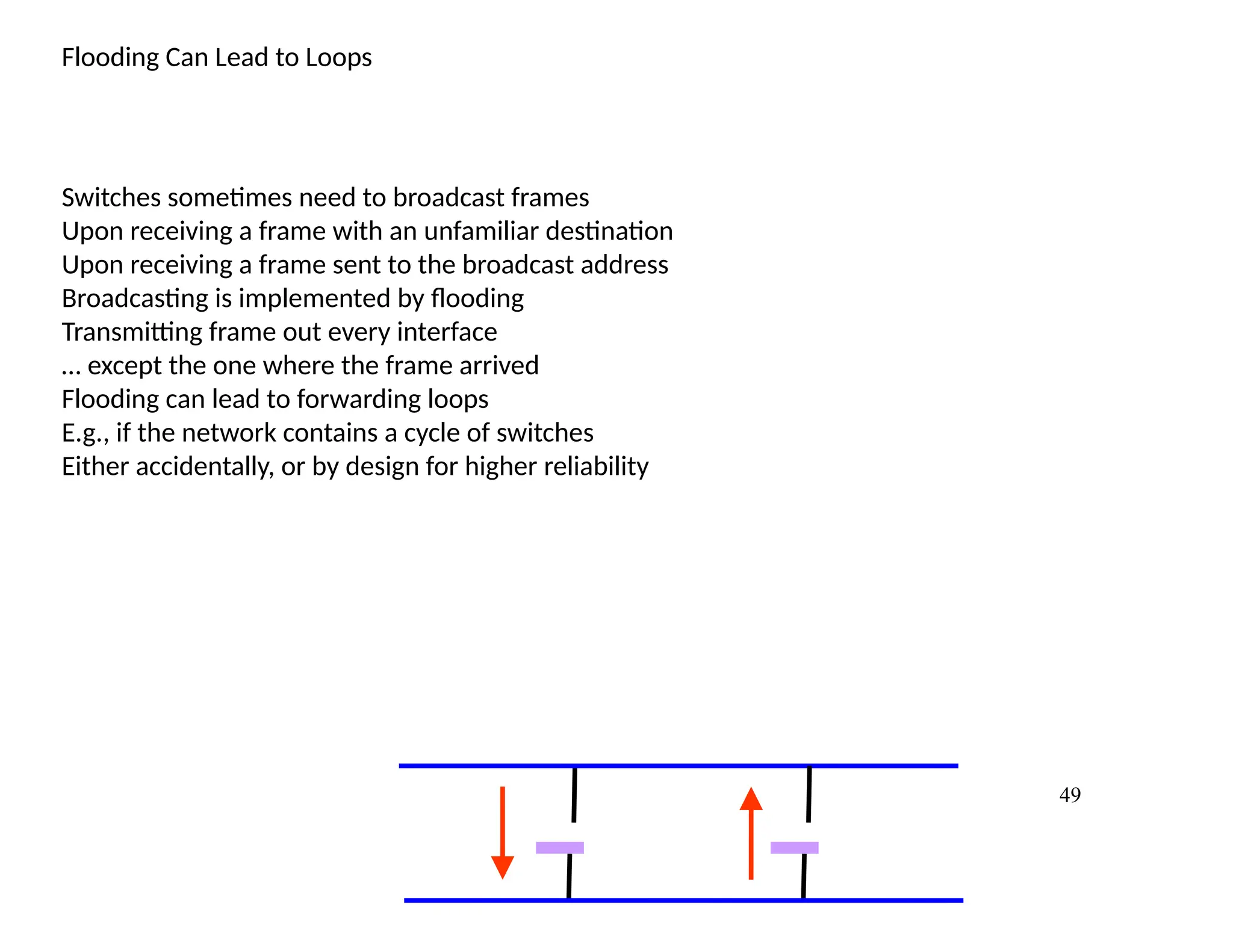
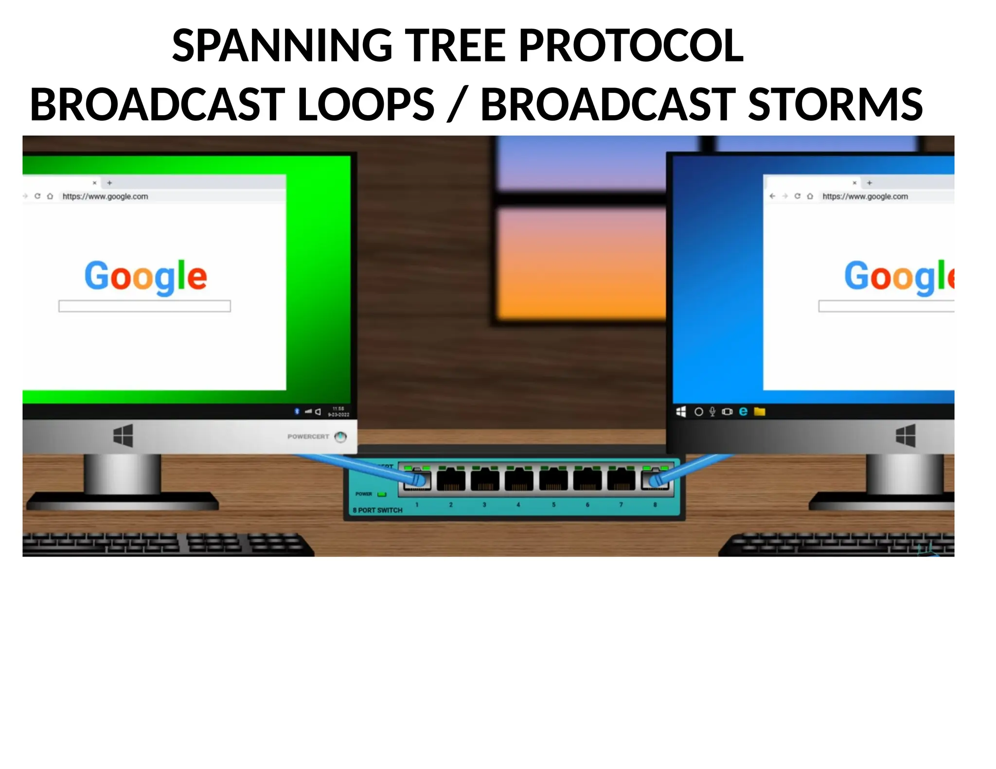
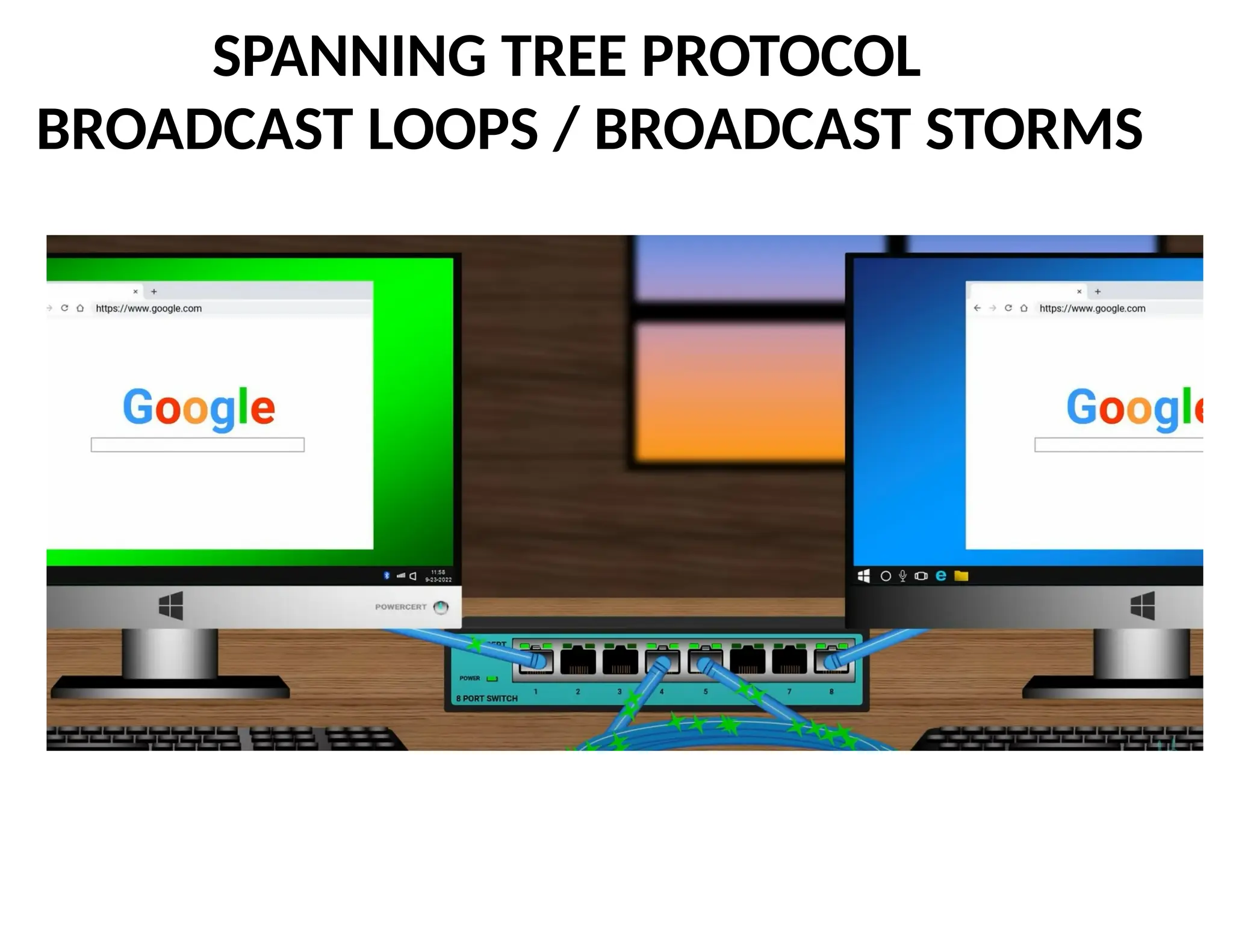
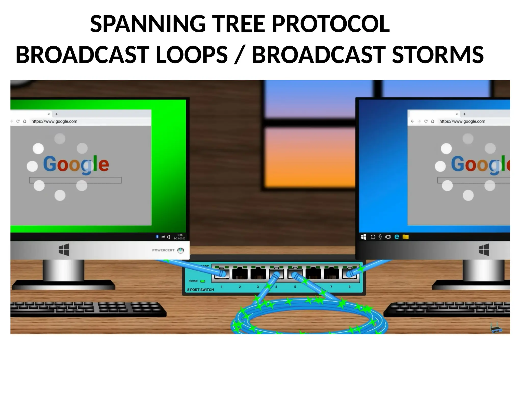
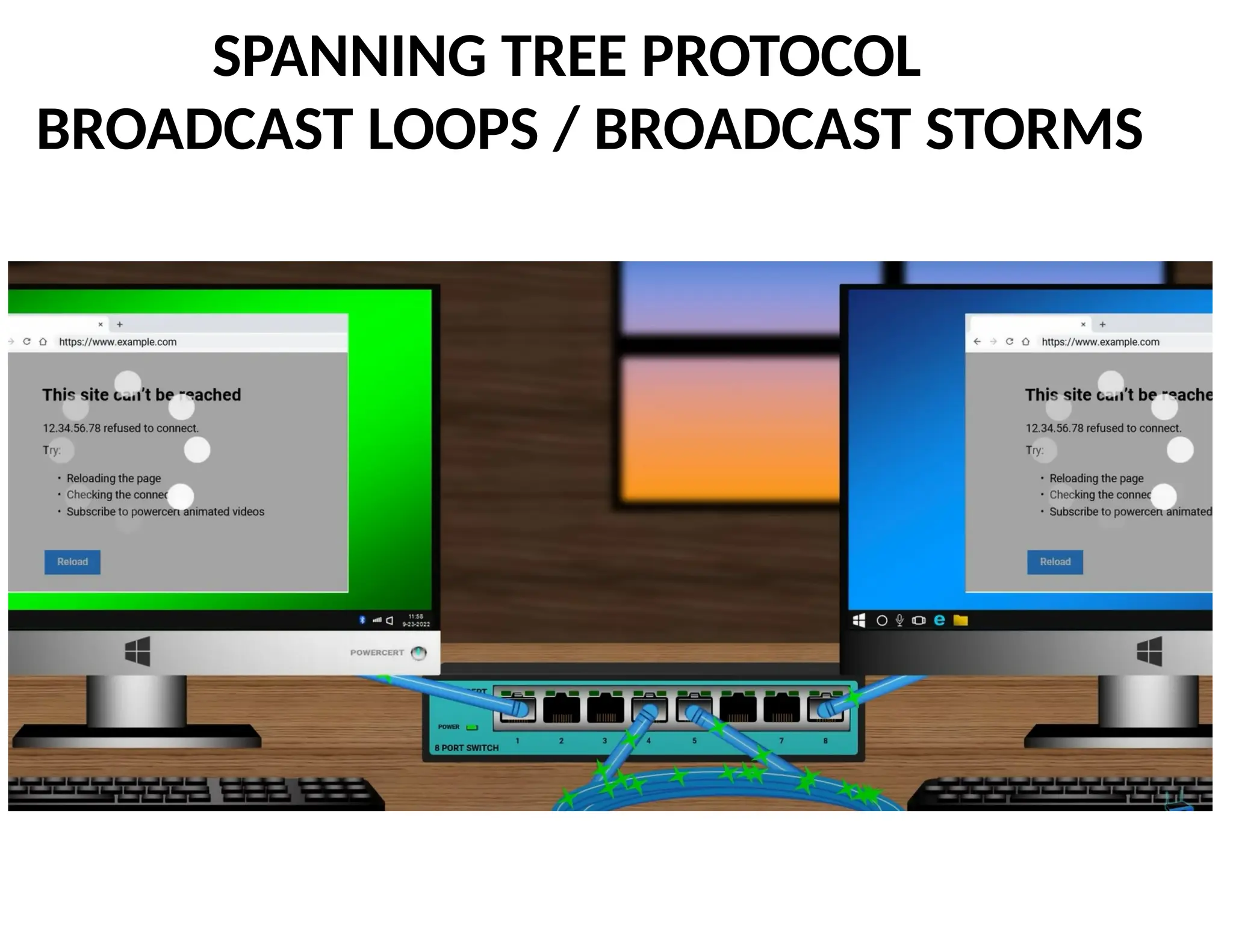
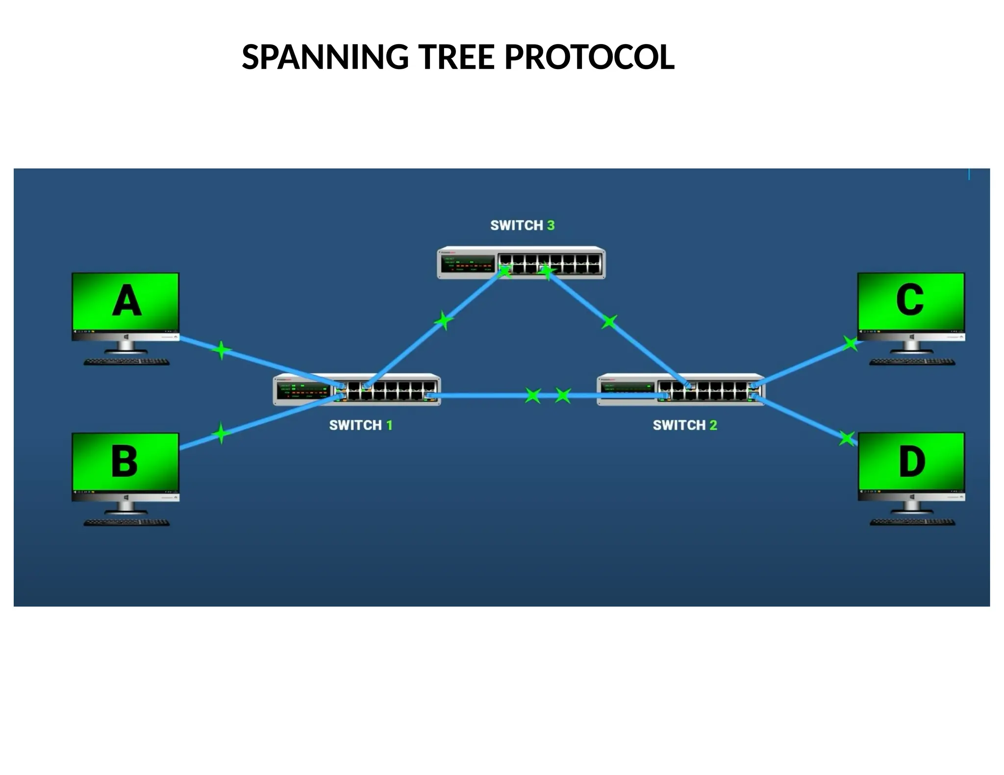
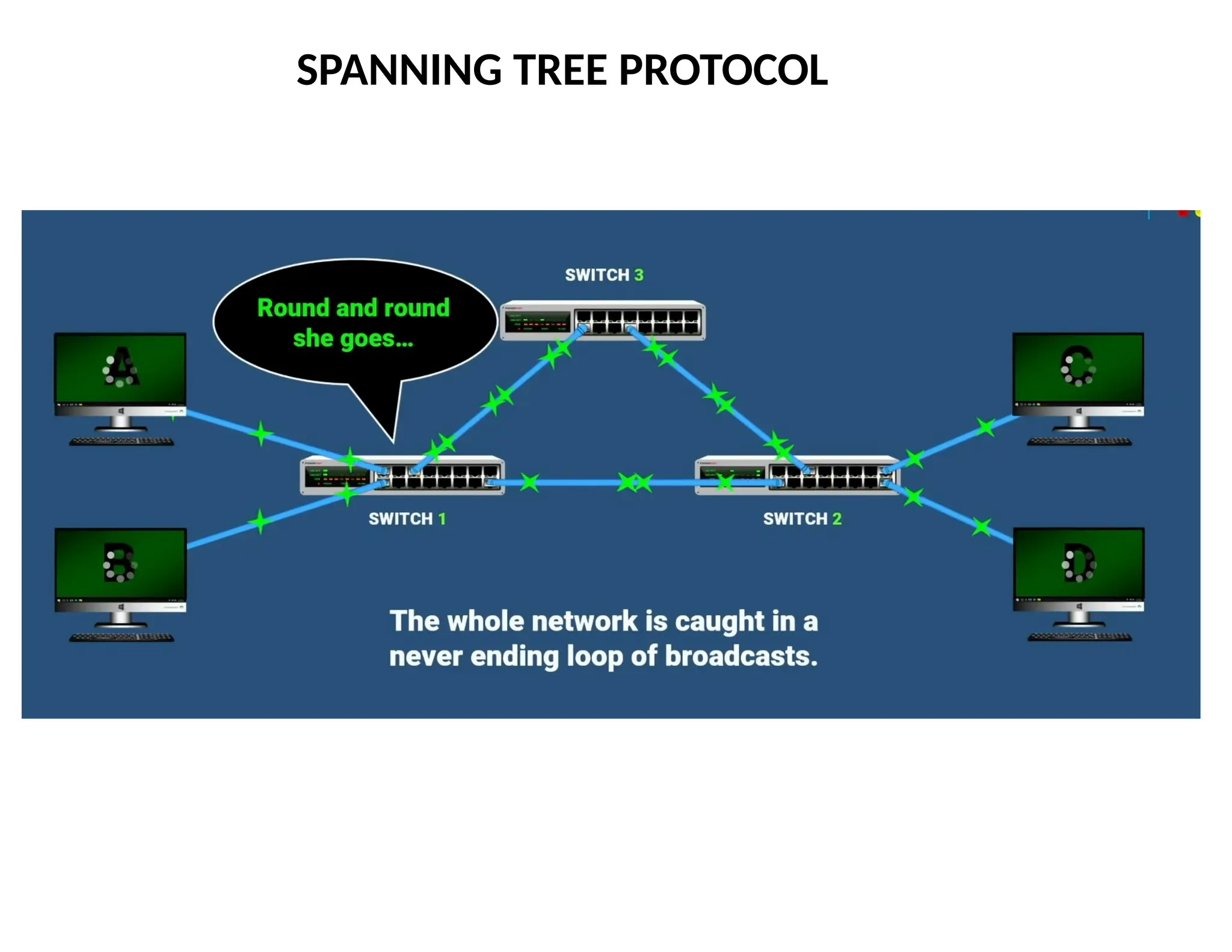
Flooding Can Leadto Loops
Switches sometimes need to broadcast frames
Upon receiving a frame with an unfamiliar destination
Upon receiving a frame sent to the broadcast address
Broadcasting is implemented by flooding
Transmitting frame out every interface
… except the one where the frame arrived
Flooding can lead to forwarding loops
E.g., if the network contains a cycle of switches
Either accidentally, or by design for higher reliability
77
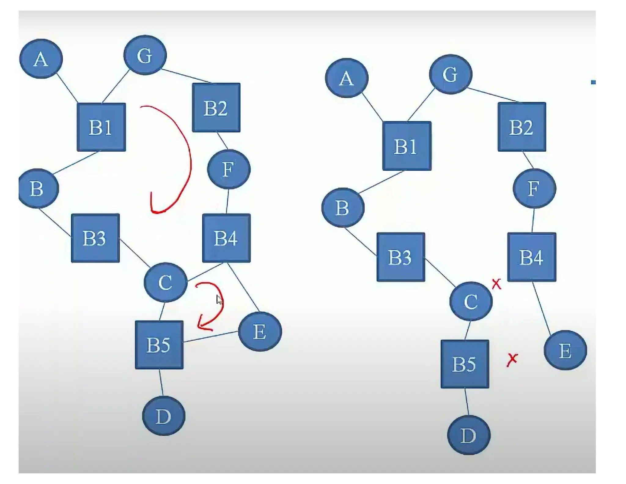
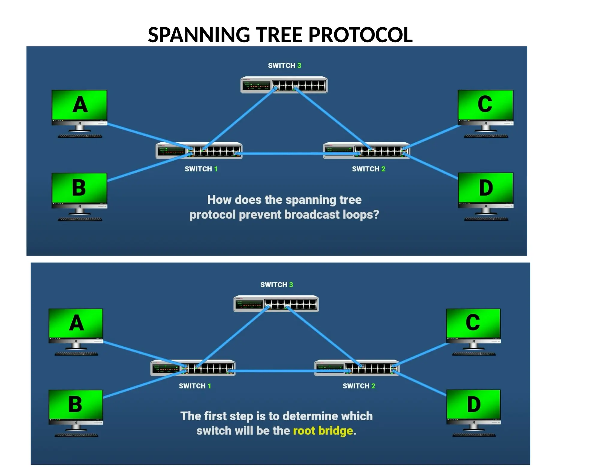
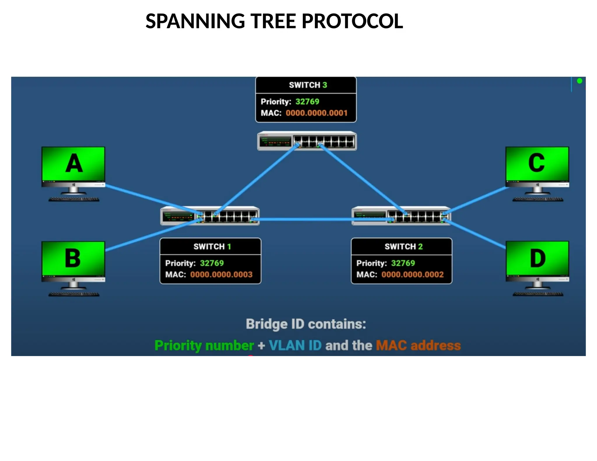
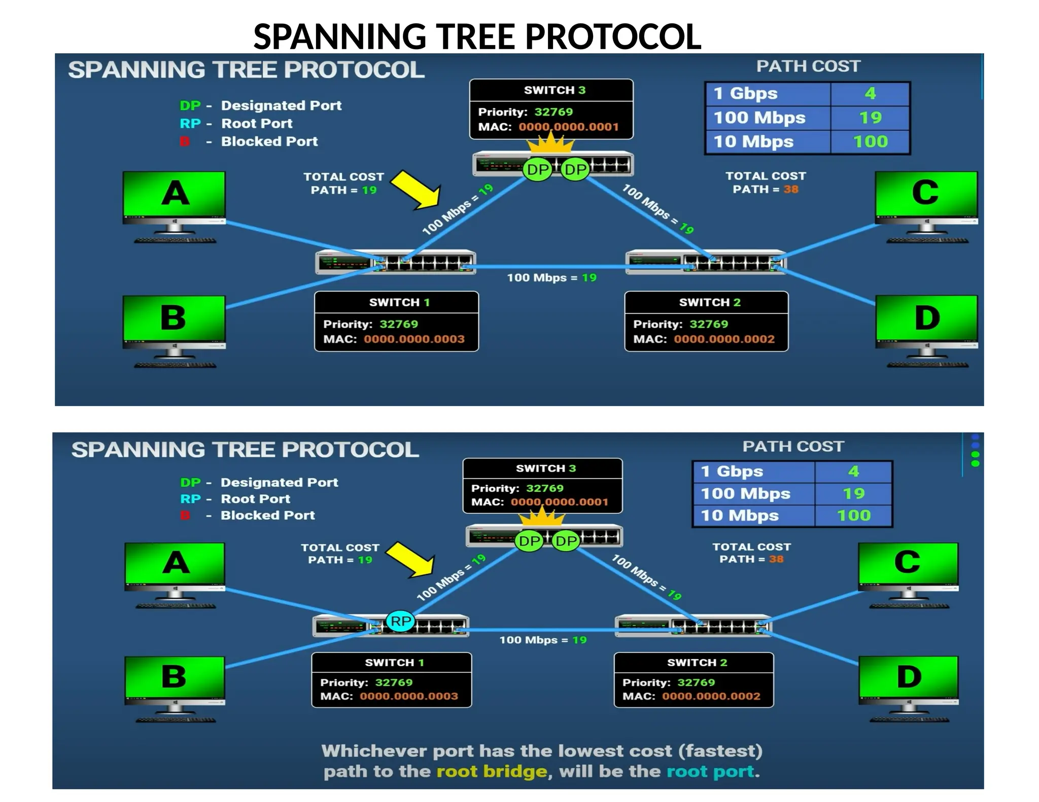
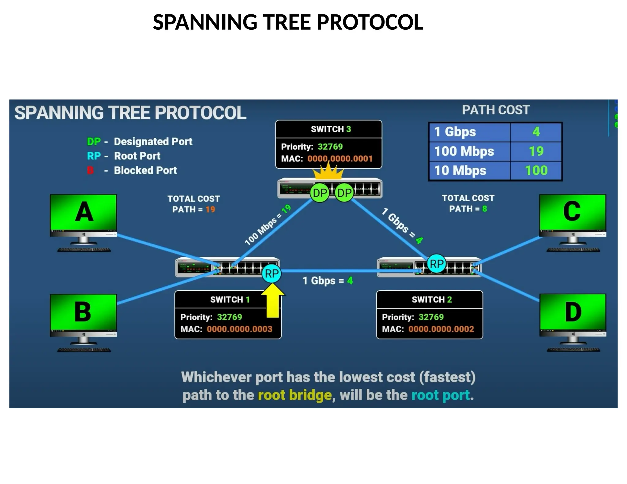
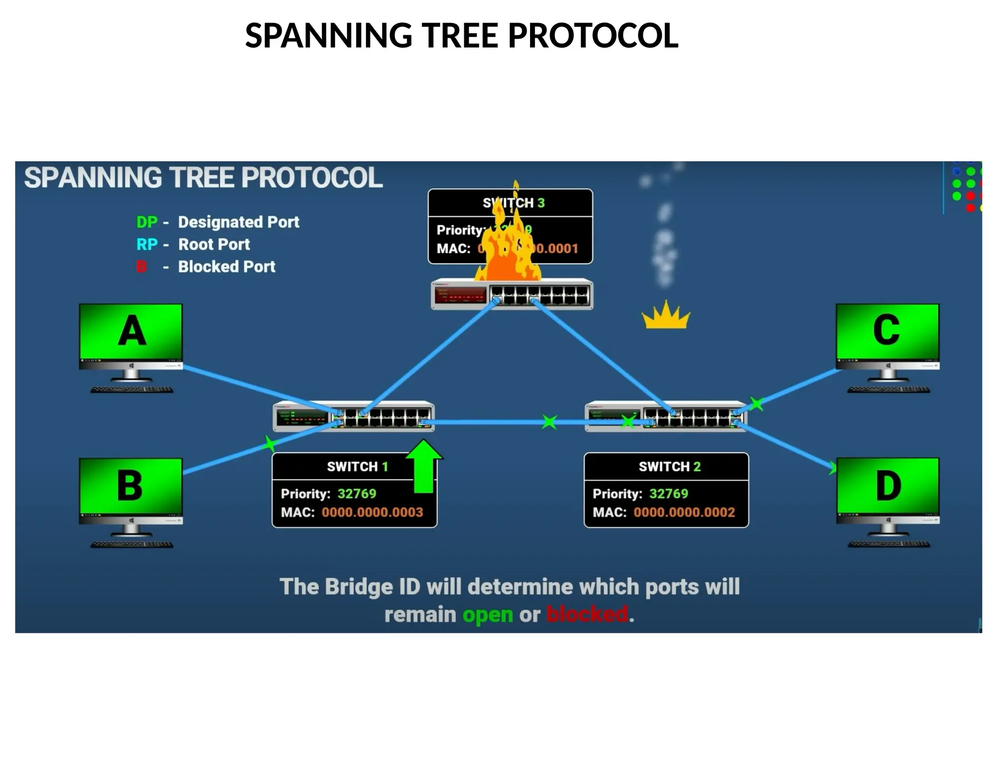
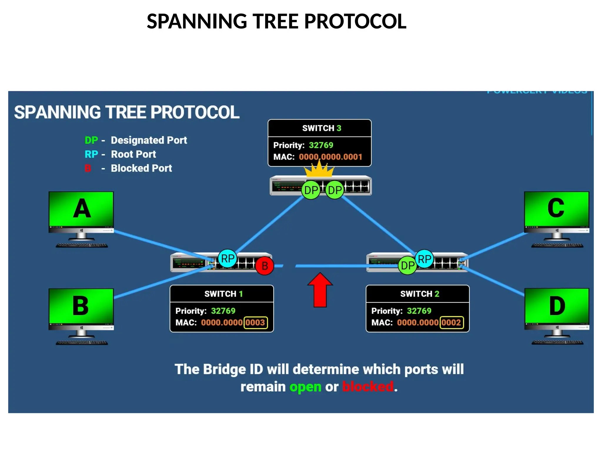
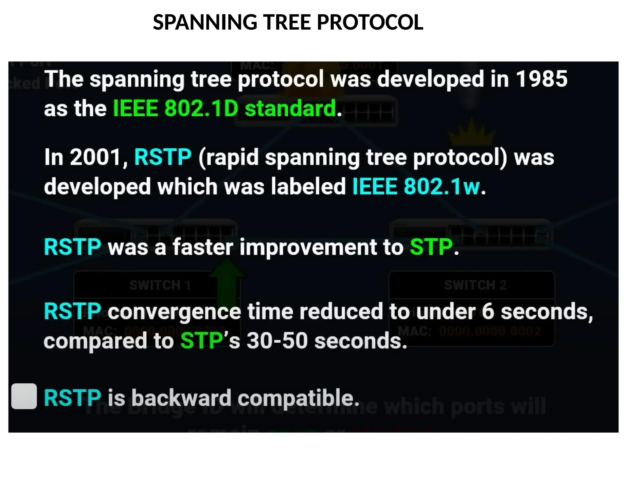
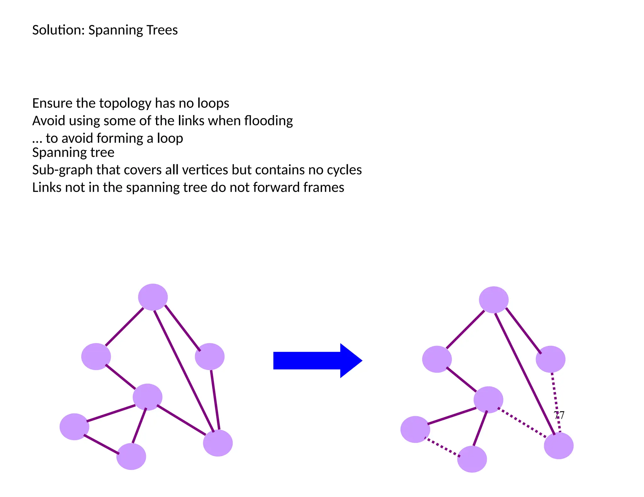
Solution: Spanning Trees
Ensurethe topology has no loops
Avoid using some of the links when flooding
… to avoid forming a loop
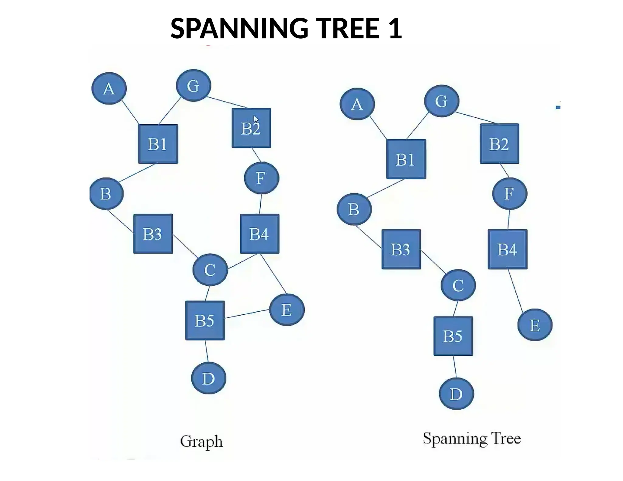
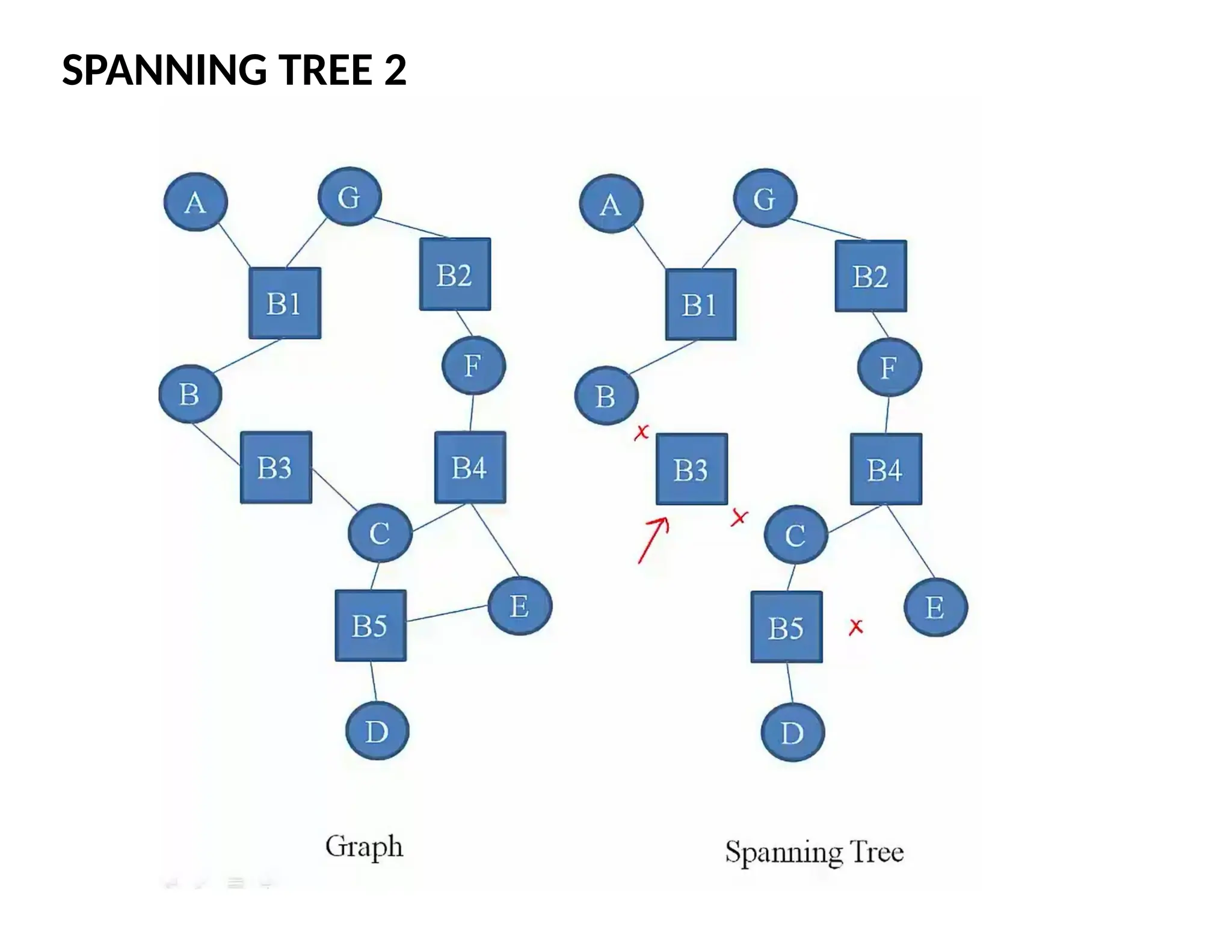
Spanning tree
Sub-graph that covers all vertices but contains no cycles
Links not in the spanning tree do not forward frames
78.
78
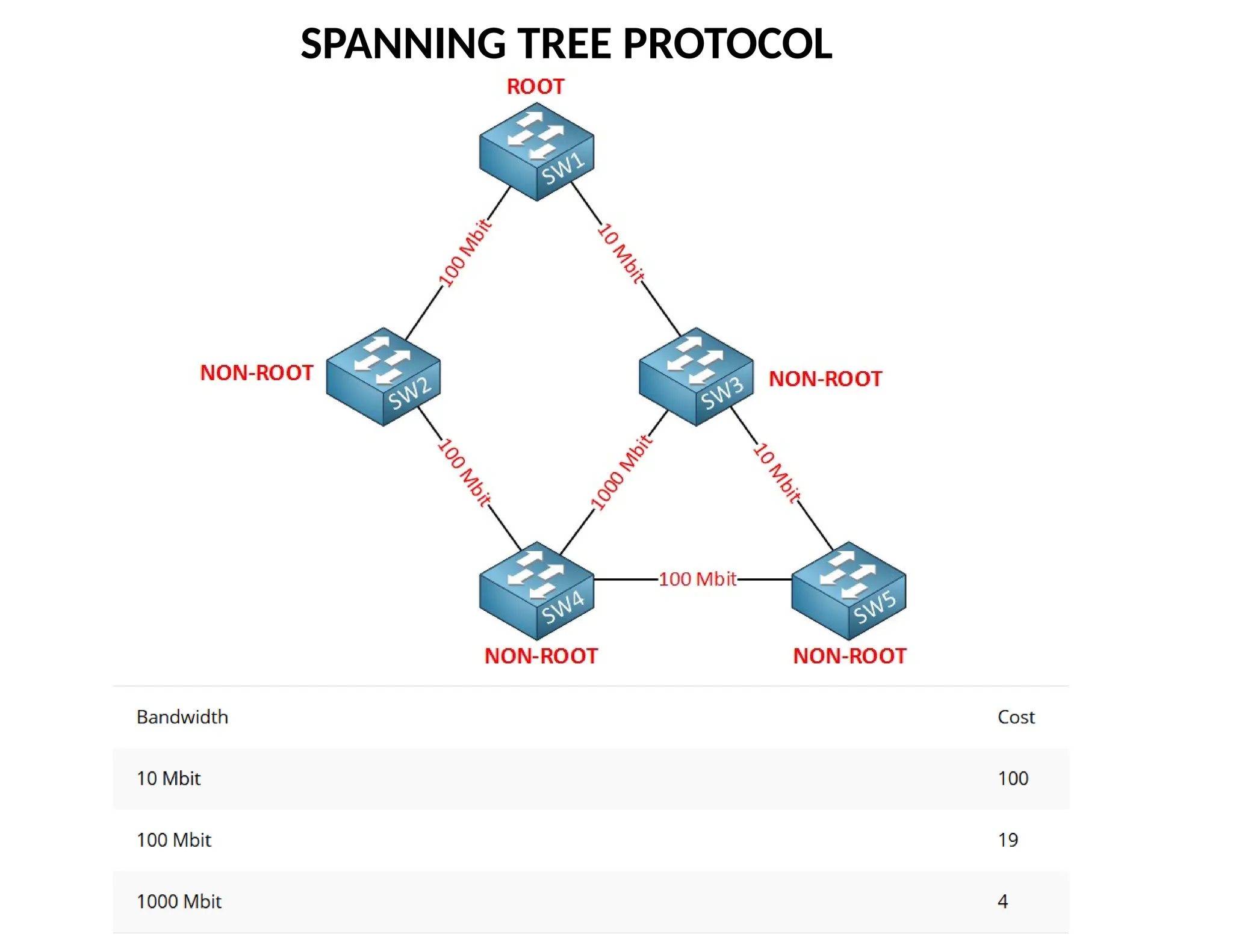
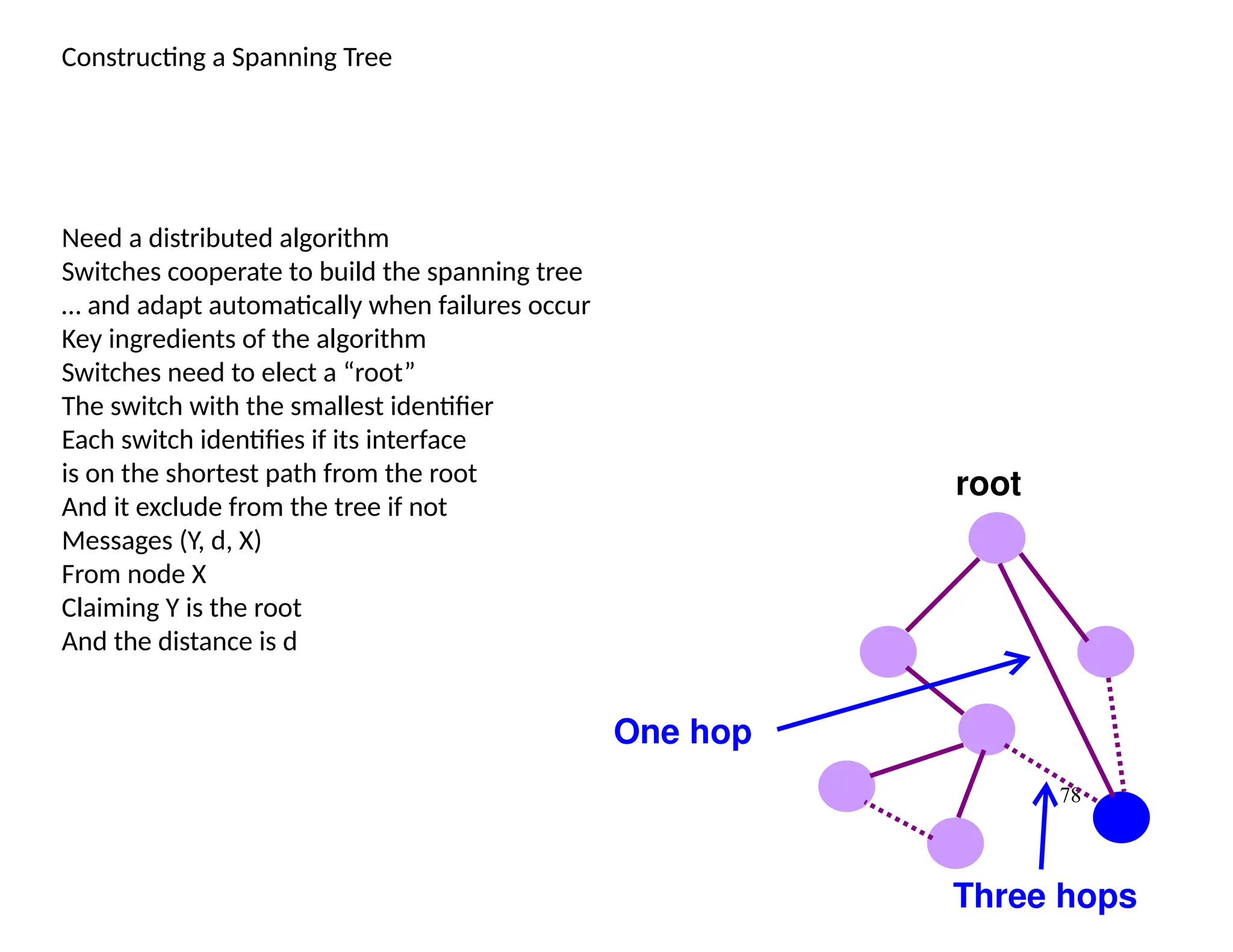
Constructing a SpanningTree
Need a distributed algorithm
Switches cooperate to build the spanning tree
… and adapt automatically when failures occur
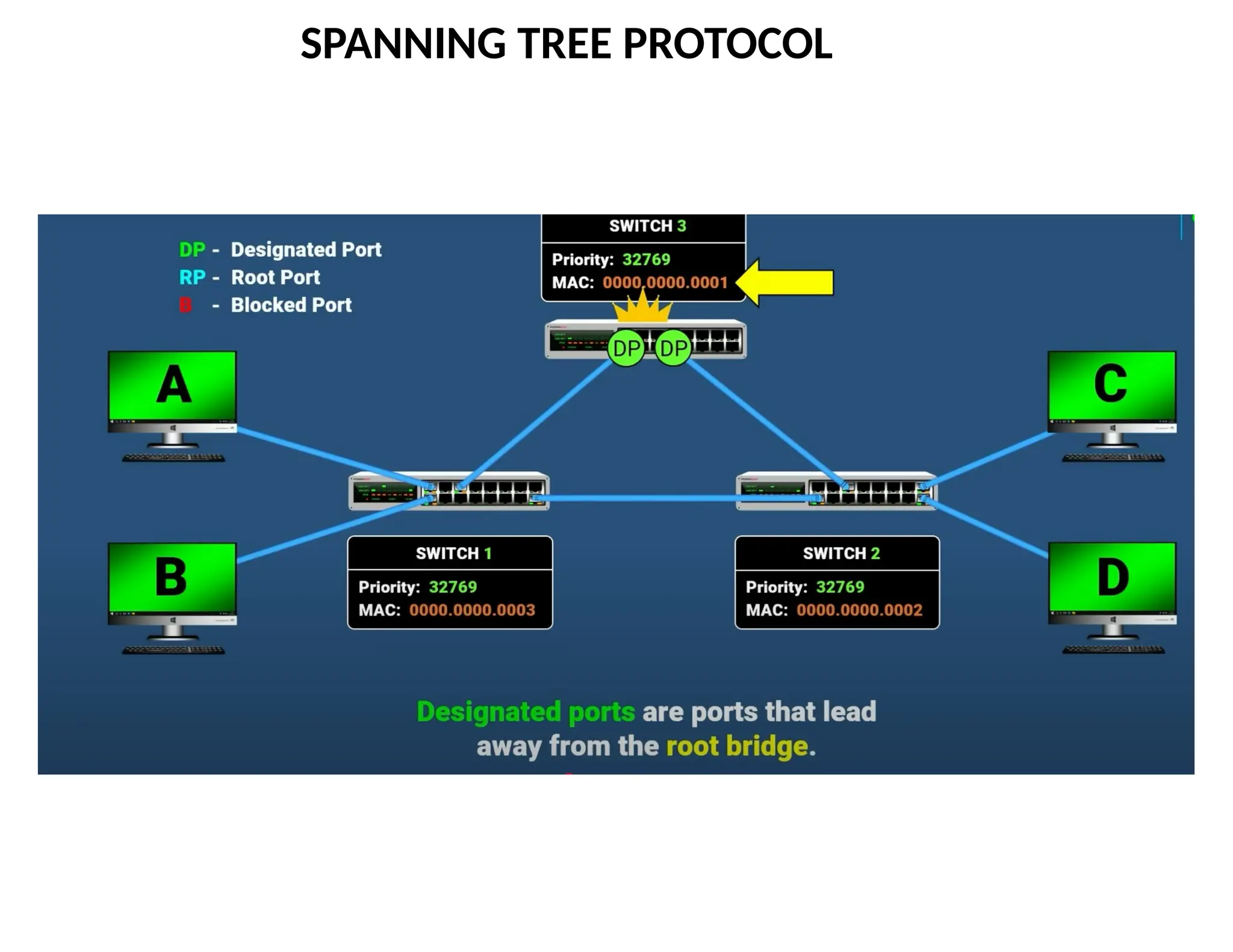
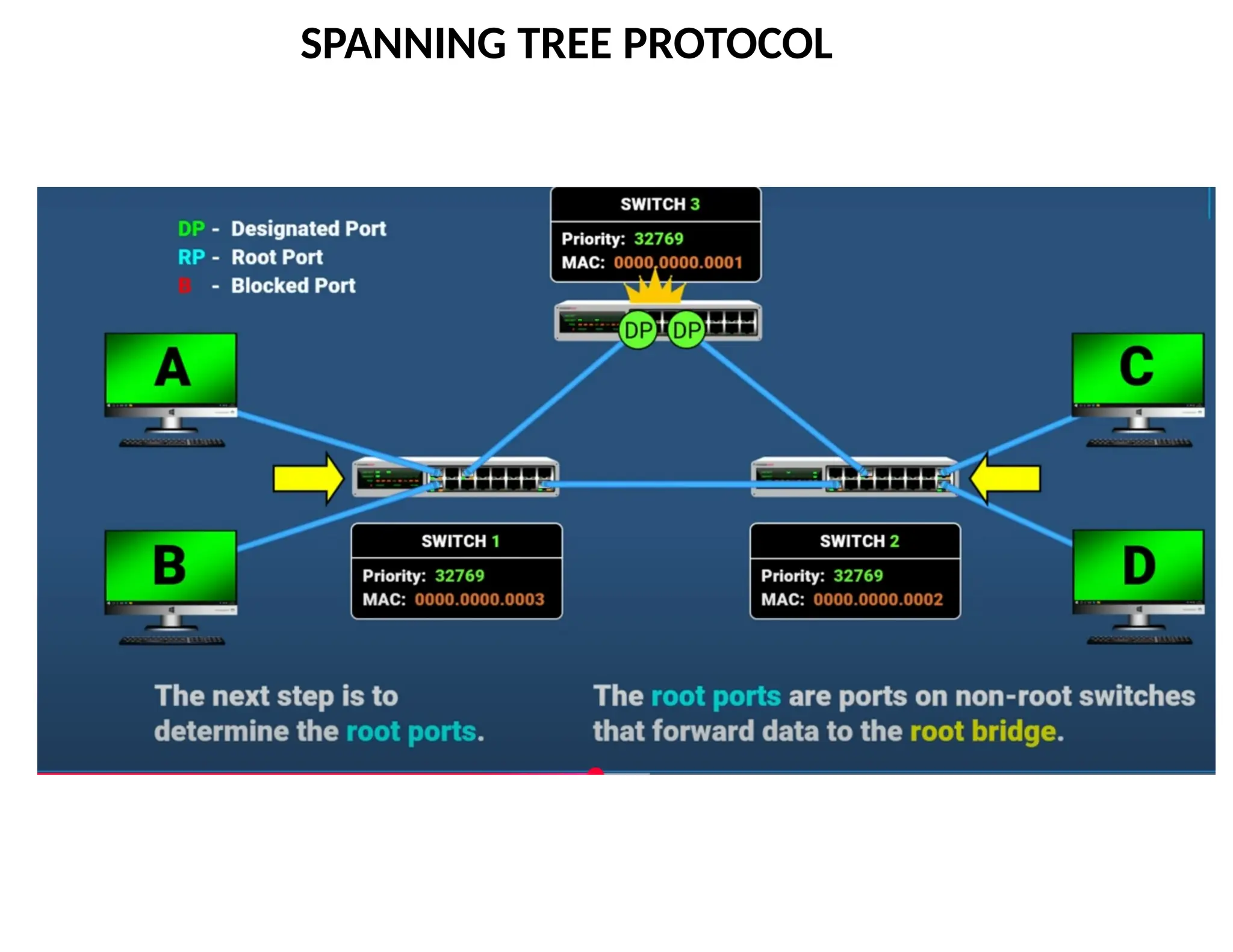
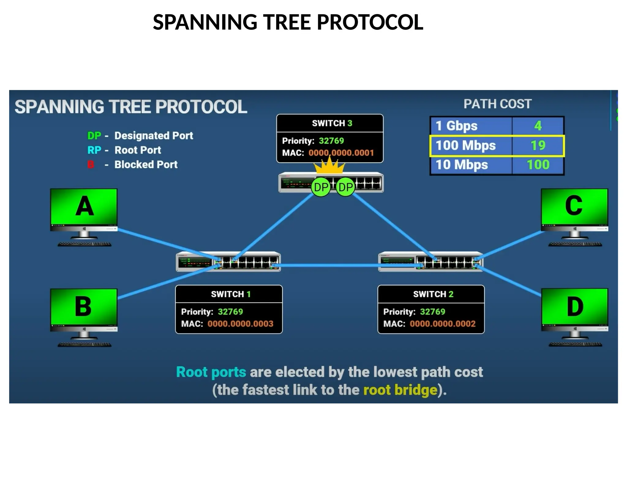
Key ingredients of the algorithm
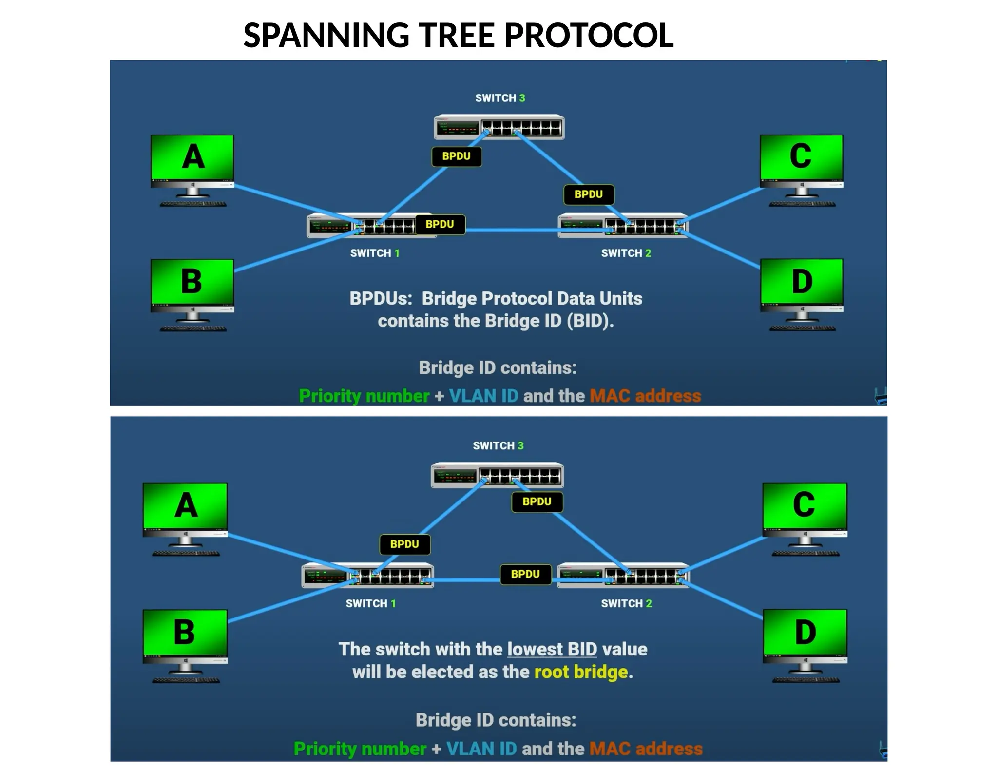
Switches need to elect a “root”
The switch with the smallest identifier
Each switch identifies if its interface
is on the shortest path from the root
And it exclude from the tree if not
Messages (Y, d, X)
From node X
Claiming Y is the root
And the distance is d
root
One hop
Three hops
79.
79
Steps in SpanningTree Algorithm
Initially, each switch thinks it is the root
Switch sends a message out every interface
… identifying itself as the root with distance 0
Example: switch X announces (X, 0, X)
Switches update their view of the root
Upon receiving a message, check the root id
If the new id is smaller, start viewing that switch as root
Switches compute their distance from the root
Add 1 to the distance received from a neighbor
Identify interfaces not on a shortest path to the root
… and exclude them from the spanning tree
80.
80
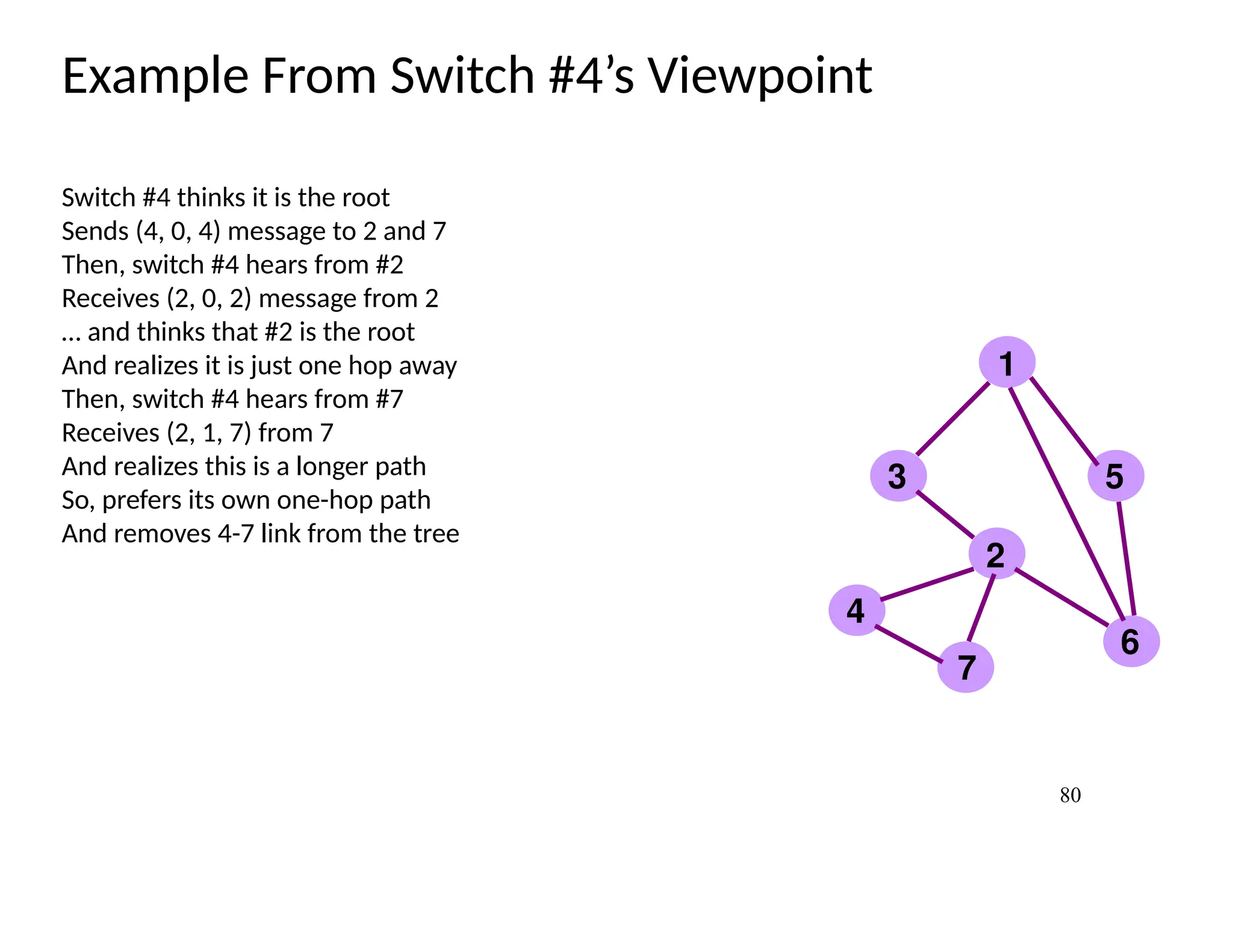
Example From Switch#4’s Viewpoint
Switch #4 thinks it is the root
Sends (4, 0, 4) message to 2 and 7
Then, switch #4 hears from #2
Receives (2, 0, 2) message from 2
… and thinks that #2 is the root
And realizes it is just one hop away
Then, switch #4 hears from #7
Receives (2, 1, 7) from 7
And realizes this is a longer path
So, prefers its own one-hop path
And removes 4-7 link from the tree
1
2
3
4
5
6
7
81.
81
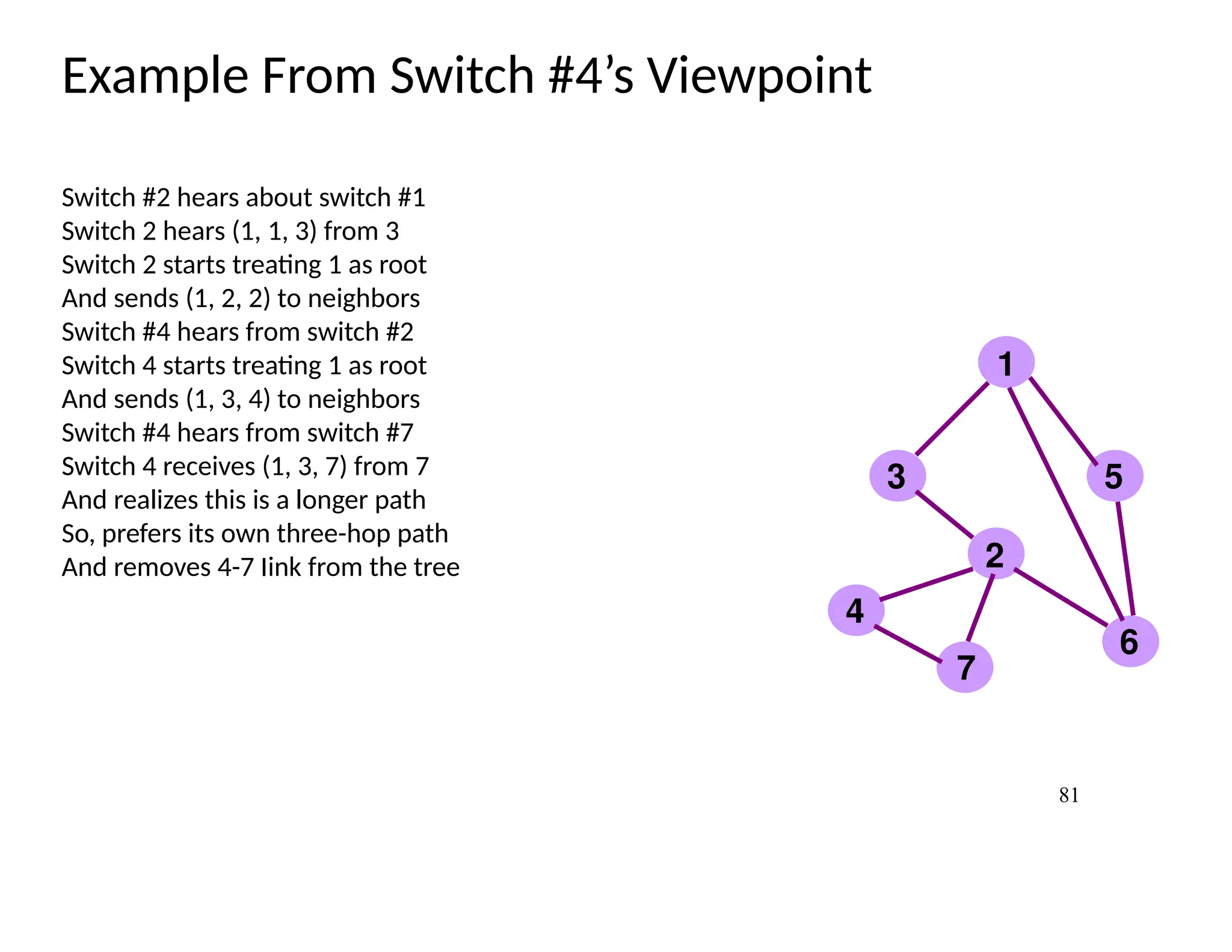
Example From Switch#4’s Viewpoint
Switch #2 hears about switch #1
Switch 2 hears (1, 1, 3) from 3
Switch 2 starts treating 1 as root
And sends (1, 2, 2) to neighbors
Switch #4 hears from switch #2
Switch 4 starts treating 1 as root
And sends (1, 3, 4) to neighbors
Switch #4 hears from switch #7
Switch 4 receives (1, 3, 7) from 7
And realizes this is a longer path
So, prefers its own three-hop path
And removes 4-7 Iink from the tree
1
2
3
4
5
6
7
82.
82
Robust Spanning TreeAlgorithm
Algorithm must react to failures
Failure of the root node
Need to elect a new root, with the next lowest identifier
Failure of other switches and links
Need to recompute the spanning tree
Root switch continues sending messages
Periodically reannouncing itself as the root (1, 0, 1)
Other switches continue forwarding messages
Detecting failures through timeout (soft state!)
Switch waits to hear from others
Eventually times out and claims to be the root
See Section 3.2.2 in the textbook for details and another example