Downloaded 160 times


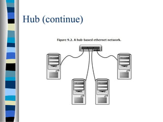


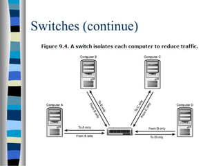


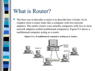


The document discusses various types of network hardware including bridges, hubs, switches, and routers. Bridges operate at the data link layer and forward packets based on physical addresses. Hubs simply repeat all signals received on one port to all other ports. Switches are smarter than hubs and only forward frames to the port associated with the destination address. Routers operate at the network layer and filter traffic based on logical IP addresses, allowing different network types to connect. Routing tables map destination networks to the next hop, whether a directly connected network or the address of the next downstream router.