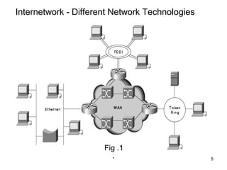
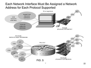
2. Recap
In the previous topics, you have learnt about
• Point to point networks
• Point to multipoint networks
• Applications of above networks
* 2
3. Objectives
On the completion of this topic, you would be
able to understand about
• What is an internet?
• History of Internetworking
• Internetworking challenges
• Open System Interconnection Reference Model
• Inter network Addressing
* 3
4. What is an Internetwork?
• An internetwork is a collection of individual networks,
connected by intermediate networking devices, that
functions as a single large network
• Internetworking refers to the industry, products, and
procedures that meet the challenge of creating and
administering internetworks
• Figure 1 illustrates some different kinds of network
technologies that can be interconnected by routers and
other networking devices to create an internetwork
* 4
6. History of Internetworking
• The first networks were time-sharing networks that used
mainframes and attached terminals. Such environments
were implemented by both IBM's Systems Network
Architecture (SNA) and Digital's network architecture
• Local-area networks (LANs) evolved around the PC
revolution. LANs enabled multiple users in a relatively small
geographical area to exchange files and messages, as well
as access shared resources such as file servers and printers
* 6
7. History of internetworking
• Wide-area networks (WANs) interconnect LANs with
geographically dispersed users to create connectivity
• Some of the technologies used for connecting LANs include
T1, T3, ATM, ISDN, ADSL, Frame Relay, radio links, and
others
• Today, high-speed LANs and switched internetworks are
becoming widely used, largely because they operate at
very high speeds and support such high-bandwidth
applications as multimedia and videoconferencing
* 7
8. History of internetworking
• Internetworking evolved as a solution to three key
problems: isolated LANs, duplication of resources, and a
lack of network management
• Duplication of resources meant that the same hardware
and software had to be supplied to each office or
department, as did separate support staff
• This lack of network management meant that no centralized
method of managing and troubleshooting networks existed
* 8
9. Internetworking Challenges
• Implementing a functional internetwork is no simple task.
many challenges must be faced, especially in the areas of
connectivity, reliability, network management, and flexibility
• The challenge when connecting various systems is to
support communication among variety of technologies
• Different sites, for example, may use different types of media
operating at varying speeds, or may even include different
types of systems that need to communicate
* 9
10. Open System Interconnection Reference Model
• The Open System Interconnection (OSI) reference model
describes how information from a software application in one
computer moves through a network medium to a software
application in another computer
• The OSI reference model is a conceptual model composed of
seven layers, each specifying particular network functions
* 10
11. OSI model
The following list details the seven layers of the Open
System Interconnection (OSI) reference model
• Layer 7—Application
• Layer 6—Presentation
• Layer 5—Session
• Layer 4—Transport
• Layer 3—Network
• Layer 2—Data link
• Layer 1—Physical
* 11
12. The OSI Reference Model Contains
Seven Independent Layers
Fig .2 * 12
13. Internetwork Addressing
• Inter network addresses identify devices separately
or as members of a group
• Addressing schemes vary depending on the
protocol family and the OSI layer
• Three types of internetwork addresses are
commonly used
data link layer addresses, Media Access
Control (MAC) addresses, and network layer
addresses
* 13
14. Data Link Layer Addresses
• A data link layer address uniquely identifies each physical
network connection of a network device
• Data-link addresses sometimes are referred to as physical
or hardware addresses
• Data-link addresses usually exist within a flat address
space and have a pre-established and typically fixed
relationship to a specific device
* 14
15. Each Interface on a Device Is Uniquely Identified
by a Data-Link Address
Fig .3
* 15
16. Data link layer addresses
• End systems generally have only one physical network
connection and thus have only one data-link address
• Routers and other internetworking devices typically
have multiple physical network connections and
therefore have multiple data-link addresses
• Figure3 illustrates how each interface on a device is
uniquely identified by a data-link address
* 16
17. Data link layer addresses
• Connection-oriented network services have more
overhead than connectionless ones
• Connection-oriented services must negotiate a
connection, transfer data, and tear down the connection,
whereas a connectionless transfer can simply send the
data without the added overhead of creating and tearing
down a connection
• Each has its place in internetworks
* 17
18. MAC Addresses
• Media Access Control (MAC) addresses consist of a
subset of data link layer addresses
• MAC addresses identify network entities in LANs that
implement the IEEE MAC addresses of the data link layer
• As with most data-link addresses, MAC addresses are
unique for each LAN interface
• Figure 4 illustrates the relationship between MAC
addresses, data-link addresses, and the IEEE sub layers of
the data link layer
* 18
19. MAC Addresses, Data-Link Addresses, and the IEEE Sub
layers of the Data Link Layer are All Related
Fig .4
* 19
20. Network Layer Addresses
• A network layer address identifies an entity at the
network layer of the OSI layers
• Network addresses usually exist within a hierarchical
address space and sometimes are called virtual or
logical addresses
• The relationship between a network address and a
device is logical and unfixed; it typically is based either
on physical network characteristics
• End systems require one network layer address for
each network layer protocol that they support. (This
assumes that the device has only one physical network
connection.)
* 20
21. Network layer addresses
• Routers and other internetworking devices require one
network layer address per physical network connection for
each network layer protocol supported
• For example, a router with three interfaces each running
AppleTalk, TCP/IP, and OSI must have three network
layer addresses for each interface
• The router therefore has nine network layer addresses.
Figure 5 illustrates how each network interface must be
assigned a network address for each protocol
* 21
22. Each Network Interface Must Be Assigned a Network
Address for Each Protocol Supported
FIG .5
* 22
23. Summary
In this class, you have learnt about
• An internet
• History of Internetworking
• Open System Interconnection Reference Model
• Inter network Addressing
* 23
24. Quiz
1) __________________ is more suitable for
computer communications
a) Circuit switching
b) Packet switching
c) Message
d) none
* 24
25. Quiz
2) The _____ layer is the lowest layer in the OSI
model
a) physical
b) Transport
c) session
d) Application
* 25
26. Frequently Asked Questions
1) Explain what is an Internetwork
2) What are the challenges of Internetwork?
3) Explain the Internetwork addressing
26