Downloaded 879 times


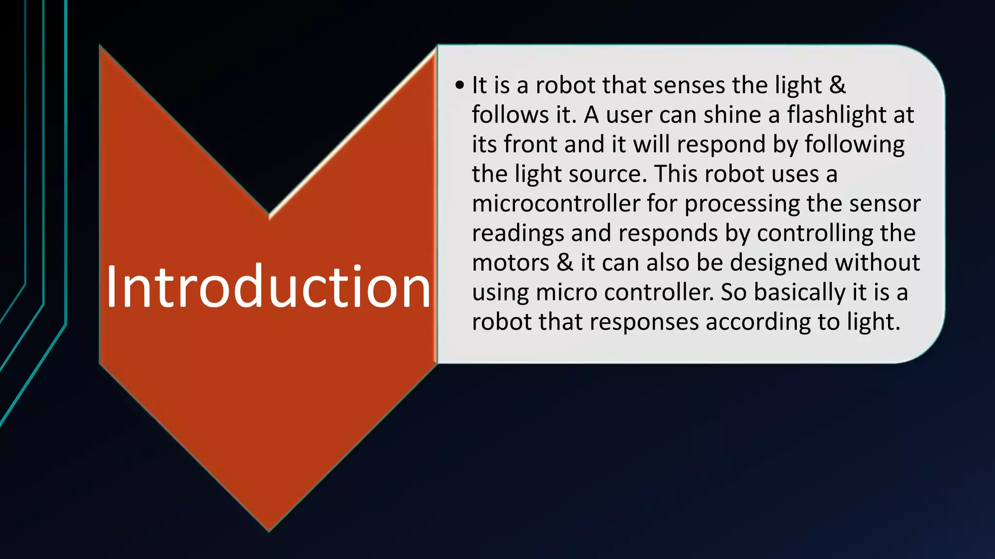


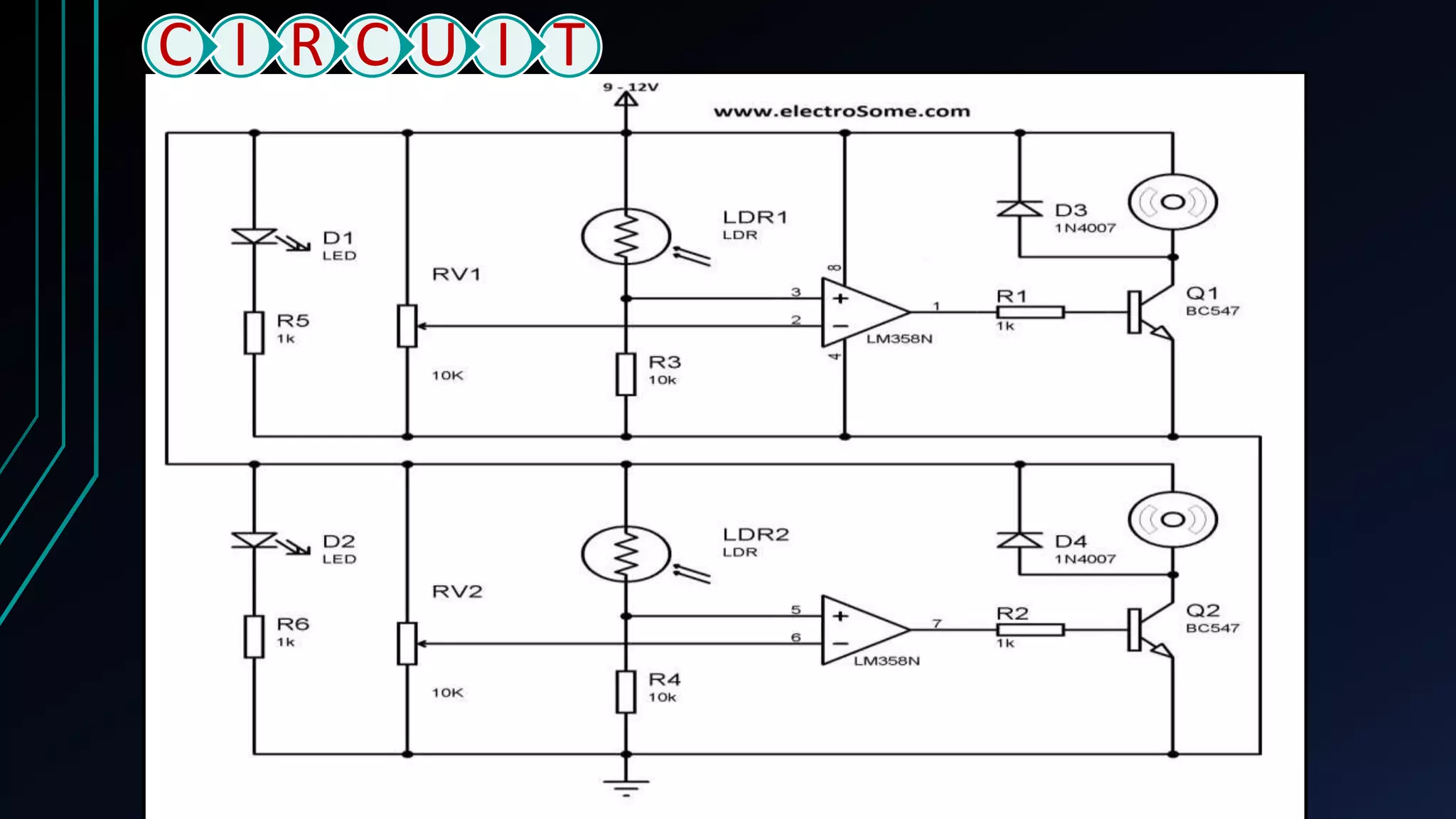
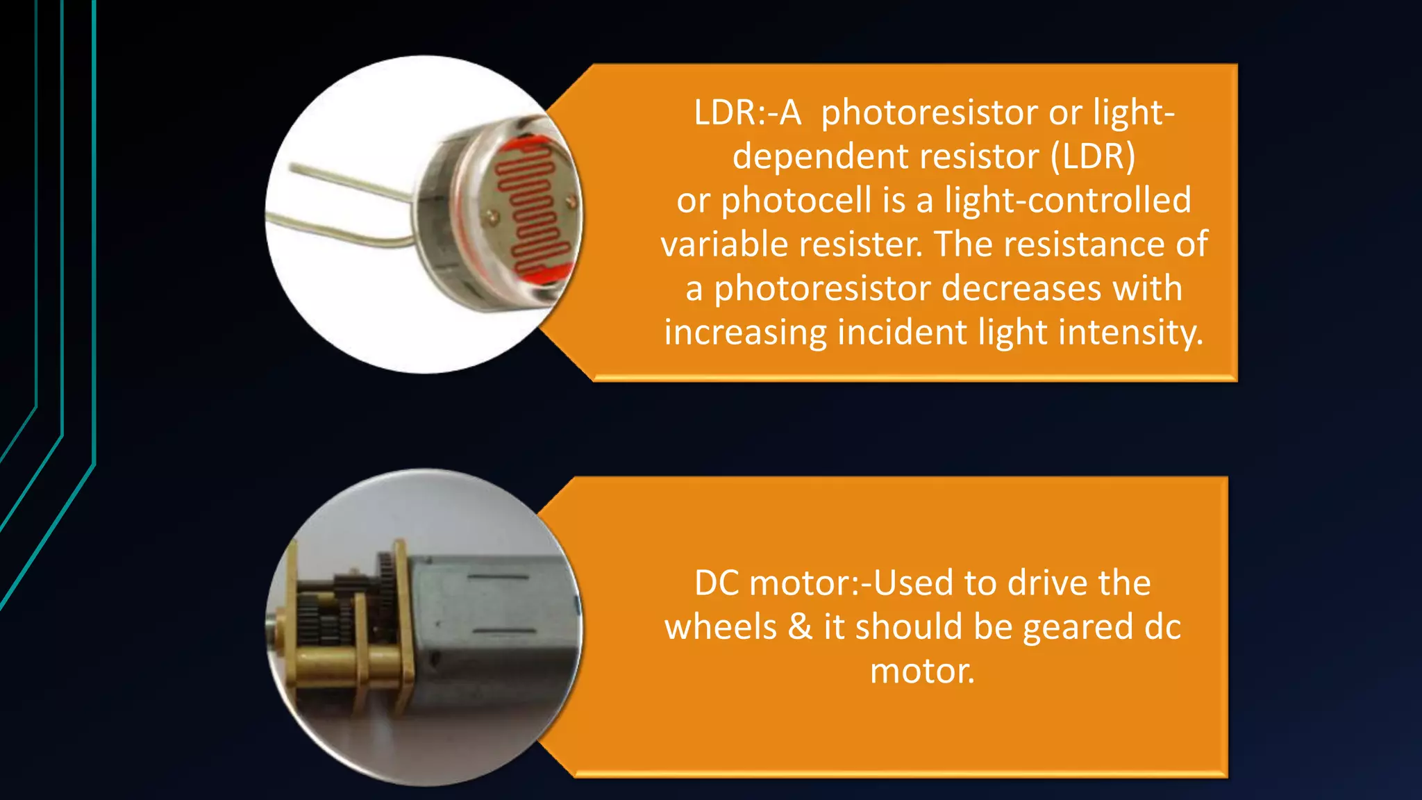
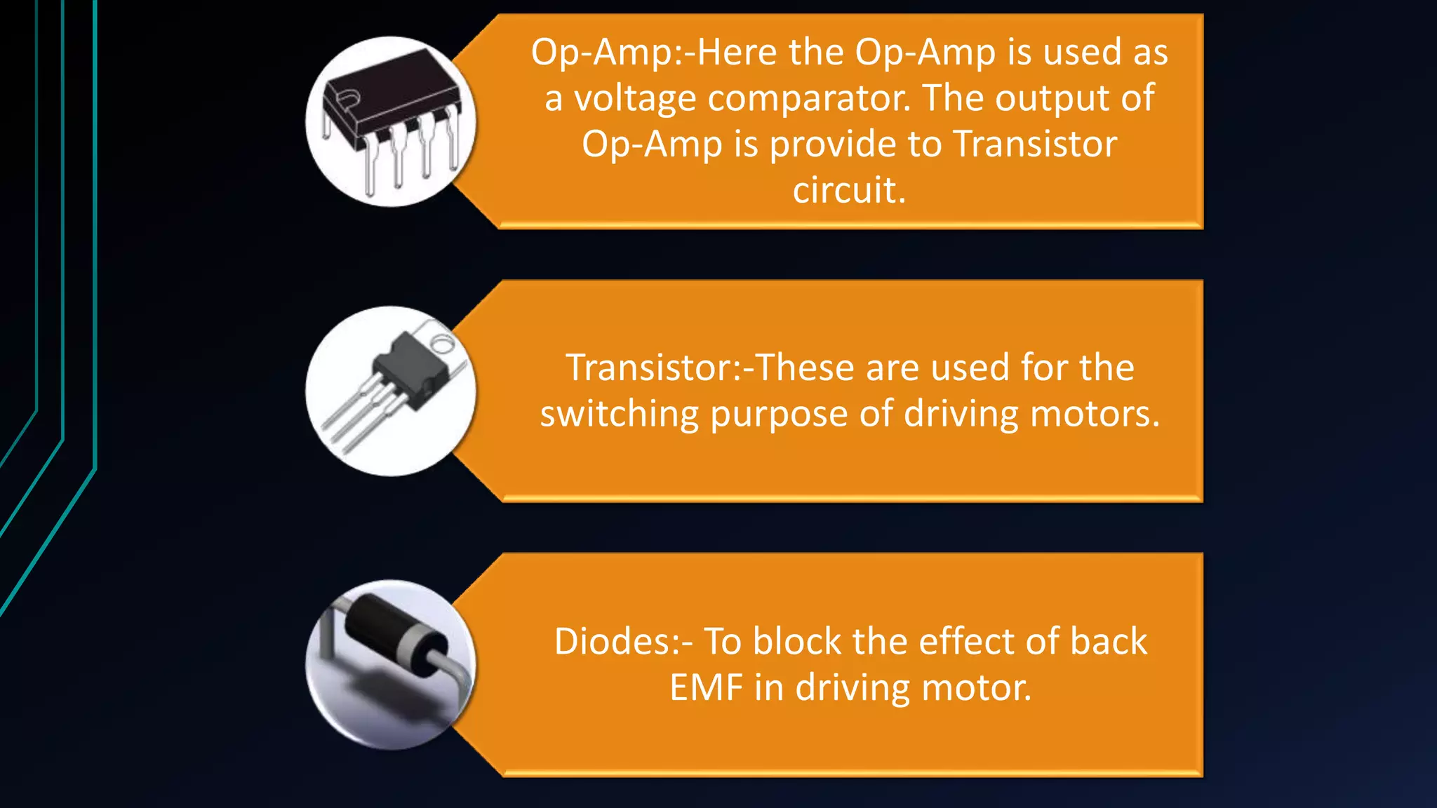


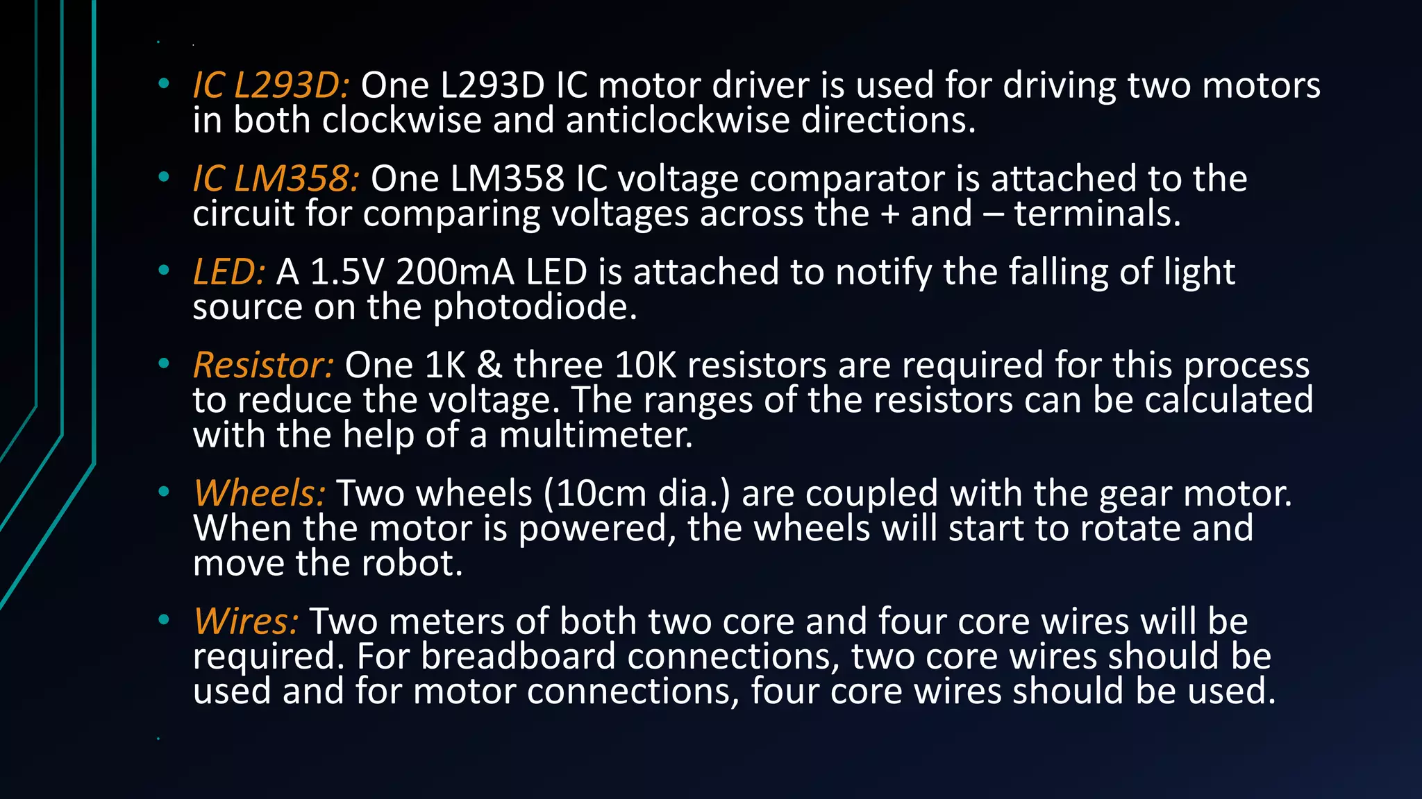


This document describes the design and functioning of a light following robot. The robot uses light dependent resistors (LDRs) to sense light and an op-amp circuit to compare the light readings from the LDRs. When more light falls on one LDR, the op-amp output activates the corresponding transistor which drives the motor on that side, causing the robot to turn towards the light source. The robot aims to follow a light source such as a flashlight by moving its motors based on the LDR sensor readings processed by the op-amp circuitry. Applications include uses in street lights, alarms, and devices that adjust screen brightness based on ambient lighting.