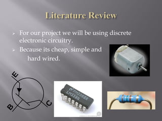
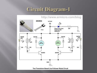
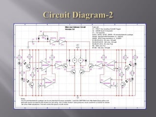
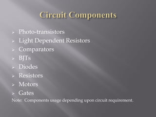
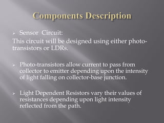
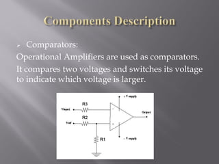
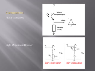
Electronics-I
Semester Project
Farooq Saeed   2009-NUST-BE-EL-25
   To design a small autonomous
    machine which can track a white
    line over a black background.
   A line follower robot is basically a machine
    designed to follow a path predetermined by
    the user.
   The path maybe as simple as a straight or a
    curved line or it maybe as complex as a 90
    degree turn and junction counting capabilities.
   In our semester project, we will concentrate on
    simple tasks.
   Line follower robot can detect bright light
    using specific sensors, and define it’s motion
    accordingly.

   Line follower senses the line using it’s sensors
    (LDR’s) and maneuvers the mechanical
    structure to stay on course while constantly
    correcting wrong moves.
    This project can be done using following ways:


1.     Using Micro-controller circuit.
2.     Using Discrete Electronic Components.
   For our project we will be using discrete
    electronic circuitry.
   Because its cheap, simple and
       hard wired.
   We have divided the project into following
    modules:

   Mechanical Design.

   Motor Speed and Direction Control.

   Light sensing Mechanism.
   The mechanical design should be light weight
    and stable.
   It should be able to support the circuit and
    motors while maintaining the balance during
    operation.
   It should be able to freely move in any
    direction without any structural hindrances.
  Motor Placement:
            The motors should be positioned in the
mechanical structure so as to allow maximum
power transfer and torque. (We might use 2 or 3
motors depending upon the final design and
situation.)
 Direction:

            Possible methods may include varying
     the motor speed or PWM.
   We will use LDR’s or photo-transistors for the
    light sensing mechanism.
   The intensity of light reflected from the surface
    will determine the resistance of LDR or the
    amount of current flowing from collector to
    emitter in the photo-transistor.
   This changed resistance or current will
    determine the speed of motors.
   The correct positioning of the sensors presents
    a feasible controlling strategy for complex as
    well as simple tasks.
   A robot will know when to turn depending on
    the location of the sensors.
   Number of sensors determines the smooth
    movement of the robot.
   Optimum distance between the sensors
    depends on number of sensors, width of
    straight line and the logic applied.
Left motor will be connected to the right
sensor and vice versa. As long as the
sensors remain on the white tape, it
continues to move in the straight direction.
But when the sensor detects the black
surface, the infra red light gets absorbed
and LDR resistance or photo transistor
current remains low and subsequently the
robot adjusts its direction by varying the
motor speed.
   Photo-transistors
   Light Dependent Resistors
   Comparators
   BJTs
   Diodes
   Resistors
   Motors
   Gates
Note: Components usage depending upon circuit requirement.
  Sensor Circuit:
This circuit will be designed using either photo-
transistors or LDRs.

   Photo-transistors allow current to pass from
    collector to emitter depending upon the intensity
    of light falling on collector-base junction.

   Light Dependent Resistors vary their values of
    resistances depending upon light intensity
    reflected from the path.
   Comparators:
Operational Amplifiers are used as comparators.
It compares two voltages and switches its voltage
to indicate which voltage is larger.
Components
Photo-transistors


Light Dependent Resistor
   D1: Submission of Project Proposal
    (12-11-2010)
   D2: Working Circuit (Breadboard) (Week 12)
   D3: Mechanical Structure (Week 14)
   D4: Full Project Demo (Week 15)
   D5: Project Report (Week 16)
   D6: Poster (SPEX ‘11)
   Project Proposal:
    Adil Khurram
    Farooq Saeed
   Working Circuit:
    Adil Khurram
    Farooq Saeed
    Haider Ali
   Mechanical Structure:
    Adil Usman
    Javed Khan
   R1: Failure of the proposed circuit.
   R2: Low Time Frame
   R3: Faulty Components
   R4: Unavailability of Components
   R5: Failure of synchronization between the
    working circuit and mechanical structure.
   This project if successfully completed will give
    us insight into practical applications of our
    Electronics-I course.
   This project will also inculcate in us the ability
    of solving real life technical problems using
    simplest of electronics components.

Line Following Robot

  • 1.
  • 2.
    Farooq Saeed 2009-NUST-BE-EL-25
  • 3.
    To design a small autonomous machine which can track a white line over a black background.
  • 4.
    A line follower robot is basically a machine designed to follow a path predetermined by the user.  The path maybe as simple as a straight or a curved line or it maybe as complex as a 90 degree turn and junction counting capabilities.  In our semester project, we will concentrate on simple tasks.
  • 5.
    Line follower robot can detect bright light using specific sensors, and define it’s motion accordingly.  Line follower senses the line using it’s sensors (LDR’s) and maneuvers the mechanical structure to stay on course while constantly correcting wrong moves.
  • 7.
    This project can be done using following ways: 1. Using Micro-controller circuit. 2. Using Discrete Electronic Components.
  • 8.
    For our project we will be using discrete electronic circuitry.  Because its cheap, simple and hard wired.
  • 9.
    We have divided the project into following modules:  Mechanical Design.  Motor Speed and Direction Control.  Light sensing Mechanism.
  • 10.
    The mechanical design should be light weight and stable.  It should be able to support the circuit and motors while maintaining the balance during operation.  It should be able to freely move in any direction without any structural hindrances.
  • 11.
     MotorPlacement: The motors should be positioned in the mechanical structure so as to allow maximum power transfer and torque. (We might use 2 or 3 motors depending upon the final design and situation.)  Direction: Possible methods may include varying the motor speed or PWM.
  • 12.
    We will use LDR’s or photo-transistors for the light sensing mechanism.  The intensity of light reflected from the surface will determine the resistance of LDR or the amount of current flowing from collector to emitter in the photo-transistor.  This changed resistance or current will determine the speed of motors.
  • 13.
    The correct positioning of the sensors presents a feasible controlling strategy for complex as well as simple tasks.  A robot will know when to turn depending on the location of the sensors.  Number of sensors determines the smooth movement of the robot.  Optimum distance between the sensors depends on number of sensors, width of straight line and the logic applied.
  • 14.
    Left motor willbe connected to the right sensor and vice versa. As long as the sensors remain on the white tape, it continues to move in the straight direction. But when the sensor detects the black surface, the infra red light gets absorbed and LDR resistance or photo transistor current remains low and subsequently the robot adjusts its direction by varying the motor speed.
  • 17.
    Photo-transistors  Light Dependent Resistors  Comparators  BJTs  Diodes  Resistors  Motors  Gates Note: Components usage depending upon circuit requirement.
  • 18.
     SensorCircuit: This circuit will be designed using either photo- transistors or LDRs.  Photo-transistors allow current to pass from collector to emitter depending upon the intensity of light falling on collector-base junction.  Light Dependent Resistors vary their values of resistances depending upon light intensity reflected from the path.
  • 19.
    Comparators: Operational Amplifiers are used as comparators. It compares two voltages and switches its voltage to indicate which voltage is larger.
  • 20.
  • 21.
    D1: Submission of Project Proposal (12-11-2010)  D2: Working Circuit (Breadboard) (Week 12)  D3: Mechanical Structure (Week 14)  D4: Full Project Demo (Week 15)  D5: Project Report (Week 16)  D6: Poster (SPEX ‘11)
  • 22.
    Project Proposal: Adil Khurram Farooq Saeed  Working Circuit: Adil Khurram Farooq Saeed Haider Ali  Mechanical Structure: Adil Usman Javed Khan
  • 23.
    R1: Failure of the proposed circuit.  R2: Low Time Frame  R3: Faulty Components  R4: Unavailability of Components  R5: Failure of synchronization between the working circuit and mechanical structure.
  • 24.
    This project if successfully completed will give us insight into practical applications of our Electronics-I course.  This project will also inculcate in us the ability of solving real life technical problems using simplest of electronics components.