IEEE_Report@Projects
•Download as DOCX, PDF•
0 likes•312 views

The document describes the design of an automatic solar-powered irrigation system. It uses a soil moisture sensor and timer circuit to automate watering. When the sensor detects dry soil, it triggers a timer that activates a water pump for a preset period to irrigate. The system is powered by solar panels and batteries, making it independent of the electric grid. It aims to minimize manual labor for farmers and save water by only irrigating as needed. The document provides details on the control circuit, irrigation circuit, circuit simulation, and concludes the system will save water and energy compared to manual irrigation.
![2
II.CIRCUIT DESCRIPTION
[control circuit]
The solar panel outputs a voltage ranging up to 21Volt
depending on the light intensity. However the voltage fromthe
solar panel also contains some transients.Since the solar panel
is mounted on rooftops, there is a good chance of getting hit
by lightning, hence a Transient Voltage Suppression Diode,
has been connected, which grounds the high spike of lightning
voltage to ground. A 33uF Capacitor filters the ripples present
in the voltage of solar panel output. The DC voltage is then
fed to the input terminal of a LM317T IC configured as a
voltage regulator, which has been adjusted to give an output
voltage of 14 Volt. The input voltage should be at least 17
Volt for the Regulator to work as expected. The 2nd LM317t
regulator is configured as a current regulator, which limits the
current to about 800mA, i.e. the charging current can’t exceed
this limit. Another Diode is connected after the current
limiting regulator which prevents the current from battery to
flow into the charging circuit. Two LEDs are connected in the
circuit to indicate the charging state.
An Atmega328 microcontroller is used to display the
measured parameters, i.e. the voltages, currents and Battery
Charge State on a 20x4 I2C LCD.
Since we are measuring DC voltage, a simple voltage divider
made with 100K resistance and10K, along with .1uf filtering
capacitor, is reliable enough to be used in this project.
However, for measuring currents, the super simple shunt
method, is not suitable, because of its huge loss of power,
since the current is in the order of 100s of milli Amperes.
Hence, we are using ACS712 20A Hall-effect Current Sensor
to measure the solar panel current and the Battery Charging
Current.
The output of the Voltage sensor and the current sensor are
voltages which vary in milli volts for change in the measuring
parameters. This voltage can be directly given to the
microcontroller’s ADC.The ADC converts this voltage into a
digital value, which is processed by the microcontroller and is
displayed on the LCD through a i2c Interface. The
communication from the microcontroller to the LCD is done
via the I2C module, which uses only two Data Wires of the
Microcontroller, instead of six, if it was to be used directly
with the LCD.
[Automatic Irrigation Circuit]
The circuit comprises a sensor part built using only one op-
amp (N1) of quad op-amp IC LM324. Op-amp N1 is
configured here as a comparator. Two stiff cop-per wires are
inserted in the soil containing plants. As long as the soil is
wet, conductivity is maintained and the circuit remains off.
When the soil dries out, the resistance between the copper
wires (sensor probes A and B) increases. If the resistance
increases beyond a preset limit, output pin 1 of op-amp N1
goes ‘low’
This triggers timer IC2 (NE 555) configured as a
monostablemultivibrator. As a result, relay RL1 is activated
for a preset time. The water pump starts immediately to supply
water to the plants. As soon as the soil becomes sufficiently
wet, the resistance between sensor probes decreases rapidly.
This causes pin 1 of op-amp N1 to go ‘high’. LED1 glows to
indicate the presence of adequate water in the soil. The
threshold point at which the output of op-amp N1 goes ‘low’
can be changed with the help of preset VR1. To arrange the
circuit, insert copper wires in the soil to a depth of about 2
cm,keeping them 3 cm apart. When the soil the water. LED1
glows up as the water reaches the probes.
For small areas a small pump such as the one used in air
coolers is able to pump enough water within 5 to 6 seconds.
The timing components for IC2 are selected accordingly. The
timing can be varied with the help of preset VR2. The circuit
is more effective indoors if one intends to use it for long
periods. This is because the water from reservoir (bucket, etc)
evaporates rapidly if it is kept in the open. For regulating the
flow of water, either a tap can be used or one end of a rubber
pipe can be blocked using Mseal compound, with holes punc-
gets dried, adjust VR1 towards ground rail until LED1 turns
off and relay RL1 is energised. The motor starts pumping
tured along its length to water several plants.](data:image/gif;base64,R0lGODlhAQABAIAAAAAAAP///yH5BAEAAAAALAAAAAABAAEAAAIBRAA7)
More Related Content
What's hot
What's hot (20)
Viewers also liked
Viewers also liked (20)
Similar to IEEE_Report@Projects
Similar to IEEE_Report@Projects (20)
IEEE_Report@Projects
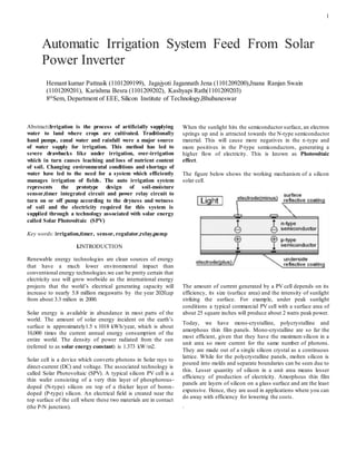
- 1. 1 Abstract:Irrigation is the process of artificially supplying water to land where crops are cultivated. Traditionally hand pumps, canal water and rainfall were a major source of water supply for irrigation. This method has led to severe drawbacks like under irrigation, over-irrigation which in turn causes leaching and loss of nutrient content of soil. Changing environmental conditions and shortage of water have led to the need for a system which efficiently manages irrigation of fields. The auto irrigation system represents the prototype design of soil-moisture sensor,timer integrated circuit and power relay circuit to turn on or off pump according to the dryness and wetness of soil and the electricity required for this system is supplied through a technology associated with solar energy called Solar Photovoltaic (SPV) Key words: irrigation,timer, sensor, regulator,relay,pump I.INTRODUCTION Renewable energy technologies are clean sources of energy that have a much lower environmental impact than conventional energy technologies.we can be pretty certain that electricity use will grow worlwide as the international energy projects that the world’s electrical generating capacity will increase to nearly 5.8 million megawatts by the year 2020,up from about 3.3 milion in 2000. Solar energy is available in abundance in most parts of the world. The amount of solar energy incident on the earth’s surface is approximately1.5 x 1018 kWh/year, which is about 10,000 times the current annual energy consumption of the entire world. The density of power radiated from the sun (referred to as solar energy constant) is 1.373 kW/m2. Solar cell is a device which converts photons in Solar rays to direct-current (DC) and voltage. The associated technology is called Solar Photovoltaic (SPV). A typical silicon PV cell is a thin wafer consisting of a very thin layer of phosphorous- doped (N-type) silicon on top of a thicker layer of boron- doped (P-type) silicon. An electrical field is created near the top surface of the cell where these two materials are in contact (the P-N junction). When the sunlight hits the semiconductor surface, an electron springs up and is attracted towards the N-type semiconductor material. This will cause more negatives in the n-type and more positives in the P-type semiconductors, generating a higher flow of electricity. This is known as Photovoltaic effect. The figure below shows the working mechanism of a silicon solar cell. The amount of current generated by a PV cell depends on its efficiency, its size (surface area) and the intensity of sunlight striking the surface. For example, under peak sunlight conditions a typical commercial PV cell with a surface area of about 25 square inches will produce about 2 watts peak power. Today, we have mono-crystalline, polycrystalline and amorphous thin film panels. Mono-crystalline are so far the most efficient, given that they have the maximum silicon in a unit area so more current for the same number of photons. They are made out of a single silicon crystal as a continuous lattice. While for the polycrystalline panels, molten silicon is poured into molds and separate boundaries can be seen due to this. Lesser quantity of silicon in a unit area means lesser efficiency of production of electricity. Amorphous thin film panels are layers of silicon on a glass surface and are the least expensive. Hence, they are used in applications where you can do away with efficiency for lowering the costs. . Automatic Irrigation System Feed From Solar Power Inverter Hemant kumar Pattnaik (1101209199), Jagajyoti Jagannath Jena (1101209200),Jnana Ranjan Swain (1101209201), Karishma Besra (1101209202), Kashyapi Rath(1101209203) 8th Sem, Department of EEE, Silicon Institute of Technology,Bhubaneswar
- 2. 2 II.CIRCUIT DESCRIPTION [control circuit] The solar panel outputs a voltage ranging up to 21Volt depending on the light intensity. However the voltage fromthe solar panel also contains some transients.Since the solar panel is mounted on rooftops, there is a good chance of getting hit by lightning, hence a Transient Voltage Suppression Diode, has been connected, which grounds the high spike of lightning voltage to ground. A 33uF Capacitor filters the ripples present in the voltage of solar panel output. The DC voltage is then fed to the input terminal of a LM317T IC configured as a voltage regulator, which has been adjusted to give an output voltage of 14 Volt. The input voltage should be at least 17 Volt for the Regulator to work as expected. The 2nd LM317t regulator is configured as a current regulator, which limits the current to about 800mA, i.e. the charging current can’t exceed this limit. Another Diode is connected after the current limiting regulator which prevents the current from battery to flow into the charging circuit. Two LEDs are connected in the circuit to indicate the charging state. An Atmega328 microcontroller is used to display the measured parameters, i.e. the voltages, currents and Battery Charge State on a 20x4 I2C LCD. Since we are measuring DC voltage, a simple voltage divider made with 100K resistance and10K, along with .1uf filtering capacitor, is reliable enough to be used in this project. However, for measuring currents, the super simple shunt method, is not suitable, because of its huge loss of power, since the current is in the order of 100s of milli Amperes. Hence, we are using ACS712 20A Hall-effect Current Sensor to measure the solar panel current and the Battery Charging Current. The output of the Voltage sensor and the current sensor are voltages which vary in milli volts for change in the measuring parameters. This voltage can be directly given to the microcontroller’s ADC.The ADC converts this voltage into a digital value, which is processed by the microcontroller and is displayed on the LCD through a i2c Interface. The communication from the microcontroller to the LCD is done via the I2C module, which uses only two Data Wires of the Microcontroller, instead of six, if it was to be used directly with the LCD. [Automatic Irrigation Circuit] The circuit comprises a sensor part built using only one op- amp (N1) of quad op-amp IC LM324. Op-amp N1 is configured here as a comparator. Two stiff cop-per wires are inserted in the soil containing plants. As long as the soil is wet, conductivity is maintained and the circuit remains off. When the soil dries out, the resistance between the copper wires (sensor probes A and B) increases. If the resistance increases beyond a preset limit, output pin 1 of op-amp N1 goes ‘low’ This triggers timer IC2 (NE 555) configured as a monostablemultivibrator. As a result, relay RL1 is activated for a preset time. The water pump starts immediately to supply water to the plants. As soon as the soil becomes sufficiently wet, the resistance between sensor probes decreases rapidly. This causes pin 1 of op-amp N1 to go ‘high’. LED1 glows to indicate the presence of adequate water in the soil. The threshold point at which the output of op-amp N1 goes ‘low’ can be changed with the help of preset VR1. To arrange the circuit, insert copper wires in the soil to a depth of about 2 cm,keeping them 3 cm apart. When the soil the water. LED1 glows up as the water reaches the probes. For small areas a small pump such as the one used in air coolers is able to pump enough water within 5 to 6 seconds. The timing components for IC2 are selected accordingly. The timing can be varied with the help of preset VR2. The circuit is more effective indoors if one intends to use it for long periods. This is because the water from reservoir (bucket, etc) evaporates rapidly if it is kept in the open. For regulating the flow of water, either a tap can be used or one end of a rubber pipe can be blocked using Mseal compound, with holes punc- gets dried, adjust VR1 towards ground rail until LED1 turns off and relay RL1 is energised. The motor starts pumping tured along its length to water several plants.
- 3. 3 III.CIRCUIT SIMULATION Case -1 When S1 is closed (i.e. soil has low resistance) Case – 2 When S1 switch is open ( I.e. soil has high resistance) Case – 3 When 555 timer receives 12v dc from the output of LM324 (i.e. at wet condition) Case – 4 When 555 timer receives 0v dc from the output of LM324 (i.e. at Dry condition)
- 4. 4 IV.CONCLUSION The aim of our project is to minimize this manual intervention by the farmer as there is no un-planned usage of water as well as electricity, a lot of water and energy is saved from being wasted. The irrigation will take place only when there is not enough moisture in the soil and the timer decides when should the pump be turned on/off . This also gives much needed rest to the farmers and also relieve them from electricity to turn on the motor for irrigation, as they don’t have to go and turn the pump on/off manually.We have taken into account not only the simplicity of the project, but also the efficiency and the cost effectiveness V.REFERENCES [1]http://en.wikipedia.org/wiki/I%C2%B2C [2]www.systronix.com/access/Systronix_20x4_lcd_brief _data.pdf [3] https://www.sparkfun.com/products/256 [4] http://diyaudioprojects.com/Technical/Voltage-Regulator/ [5] http://diyaudioprojects.com/Technical/Current-Regulator/ [6] http://embedded-lab.com/blog/?p=4469